1
/
de
12
PayPal, credit cards. Download editable-PDF and invoice in 1 second!
JGJ 7-2010 English PDF (JGJ7-2010)
JGJ 7-2010 English PDF (JGJ7-2010)
Prix habituel
$145.00 USD
Prix habituel
Prix promotionnel
$145.00 USD
Prix unitaire
/
par
Frais d'expédition calculés à l'étape de paiement.
Impossible de charger la disponibilité du service de retrait
Delivery: 3 seconds. Download true-PDF + Invoice.
Get QUOTATION in 1-minute: Click JGJ 7-2010
Historical versions: JGJ 7-2010
Preview True-PDF (Reload/Scroll if blank)
JGJ 7-2010: Technical specification for space frame structures
JGJ 7-2010
UDC JGJ
INDUSTRY STANDARD OF THE
PEOPLE’S REPUBLIC OF CHINA
P JGJ 7-2010
Filing Number. J 1072-2010
Technical Specification for Space Frame Structures
Issued on July 20, 2010 Implemented on March 1, 2011
Issued by. Ministry of Housing and Urban-Rural Construction of the People’s
Republic of China
Table of Contents
1 General Provisions ... 8
2 Terms and Symbols ... 9
2.1 Terms ... 9
2.2 Symbols ... 10
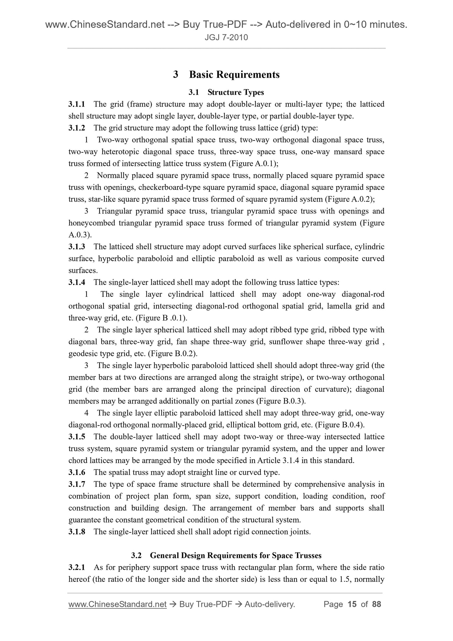
3 Basic Requirements ... 15
3.1 Structure Types ... 15
3.2 General Design Requirements for Space Trusses ... 15
3.3 General Design Requirements for Latticed Shells ... 17
3.4 General Design Requirements for Spatial Trusses, Arches and Beam String
Structures ... 18
3.5 Allowable Deflection ... 19
4 Structural Analysis ... 20
4.1 General Principles of Analysis ... 20
4.2 Static Analysis ... 21
4.3 Stability Analysis of Latticed Shells ... 23
4.4 Calculation due to Earthquake ... 24
5 Design and Details of Members and Joints ... 28
5.1 Members ... 28
5.2 Welded Hollow Spherical Joints ... 29
5.3 Bolted Spherical Joints ... 33
5.4 Embedded Hub Joints ... 37
5.5 Cast Steel Joints ... 39
5.6 Pin Joints ... 39
5.7 Joints of Composite Structures ... 40
5.8 Joints of Prestressed Cable ... 41
5.9 Supporting Joints ... 43
6 Fabrication, Erection and Acceptance ... 49
6.1 General Requirements ... 49
6.2 Requirements for Fabrication and Assembly ... 50
6.3 Assembly Elements in the Air ... 53
6.4 Erection by Strips or Blocks ... 54
6.5 Assembly by Sliding ... 55
6.6 Integral Hoisting by Derrick Masts or Cranes ... 56
6.7 Integral Lifting-up ... 58
6.8 Integral Jacking-up ... 58
6.9 Fold and Unfold Methods ... 59
6.10 Construction of Composite Space Trusses ... 60
6.11 Checking and Acceptance ... 60
Appendix A Types of Space Truss Commonly Used ... 62
Appendix B Types of Latticed Shell Commonly Used ... 65
Appendix C Equivalent Stiffness of Latticed Shells ... 67
Appendix D Simplified Method of Analysis for Composite Space Trusses ... 69
Appendix E Formula of Stability Capacity for Latticed Shells ... 71
Appendix F Formula of Multidimensional Response Spectrum ... 73
Appendix G Simplified Calculation of the Effect due to Vertical Earthquake for Roof
Trusses ... 75
Appendix H Coefficient of Forces of Latticed Shells under Horizontal Earthquake ... 77
Appendix J Formula of Primary Dimensions of Embedded Hub Joints ... 80
Appendix K Material Behavior and Details Requirements of Elastomeric Bearing Pad ... 83
Explanation of Wording in This Specification ... 87
List of Quoted Standards ... 88
1 General Provisions
1.0.1 This standard is formulated with a view to implementing the national technical and
economic policies in the design and construction of space frame structure and making the
design to be of advanced technology, safety and usability, economy and rationality and high
quality.
1.0.2 This standard is applicable to the design and construction of space frame structure
composed of steel members, including space truss, single layer or double-layer latticed shell
and spatial truss.
1.0.3 In the design of space frame structure, the reasonable structure scheme, frame/grid
layout and structure measures shall be selected according to the actual situation and the
comprehensive consideration shall be taken for material supply, processing fabrication and
onsite construction, to ensure better technical and economic effects.
1.0.4 Suspended crane shall not be arranged for single-layer latticed shell structure. Space
truss and double-layer latticed shell structures may directly withstand the suspended crane
load at Level A3 or higher level. In case the cycle times of the stress variation is larger than or
equal to 5×10⁴, the fatigue analysis shall be conducted, and the allowable stress amplitude and
the structure shall be determined by special test.
1.0.5 The design and construction of space frame structure shall comply with the
requirements in the current relevant national standards besides this standard.
2 Terms and Symbols
2.1 Terms
2.1.1 Space grid structure, space frame, space latticed structure
Spatial structure formed of member and member bar arranged in a certain rule by joint
connection, including space truss, curved latticed shell and spatial truss
2.1.2 Space truss, space grid
Flat plate type or slight curved spatial trussing structure formed of member bars arranged
in a certain rule by joint connection, mainly bearing the integral bending internal force
2.1.3 Intersecting lattice truss system
System formed of two-way or three-way intersecting lattice trusses
2.1.4 Square pyramid system
System formed of square pyramids as basic unit
2.1.5 Triangular pyramid system
System formed of triangular pyramids as basic unit
2.1.6 Composite space truss
Flat lattice truss structure formed by reinforced concrete slab as upper chord member and
steel web member and bottom chord bar
2.1.7 Latticed shell, reticulated shell
Curved spatial trussing structure or beam structure formed of member bars arranged in a
certain rule by joint connection, mainly bearing the integral thin film internal force
2.1.8 Spherical latticed shell, braced dome
Single-layer or double-layer latticed shell structure with spherical appearance
2.1.9 Cylindrical latticed shell, braced vault
Single-layer or double-layer latticed shell structure with cylindric surface appearance
2.1.10 Hyperbolic paraboloid latticed shell
Single-layer or double-layer latticed shell structure with the appearance of hyperbolic
paraboloid
2.1.11 Elliptic paraboloid latticed shell
Single-layer or double-layer latticed shell structure with the appearance of elliptic
paraboloid
2.1.12 Lamella grid
Rhombic grid cell formed of two-way heterotopic member bars
2.1.13 Ribbed type
Trapezia grid cell formed of radial and circumferential member bar on spherical face
2.1.14 Ribbed type with diagonal bars (Schwedler dome)
Triangular grid cell formed of radial, circumferential and diagonal member on spherical
face
2.1.15 Three-way grid
Equilateral triangle grid cell formed of three-way member bars
2.1.16 Fan shape three-way grid (Kiewitt dome)
Triangular grid cell formed of circumferential member bar jointly with the lamella grid
formed of parallel rods in n (n=6, 8) sector curved surfaces divided radially on a spherical
face
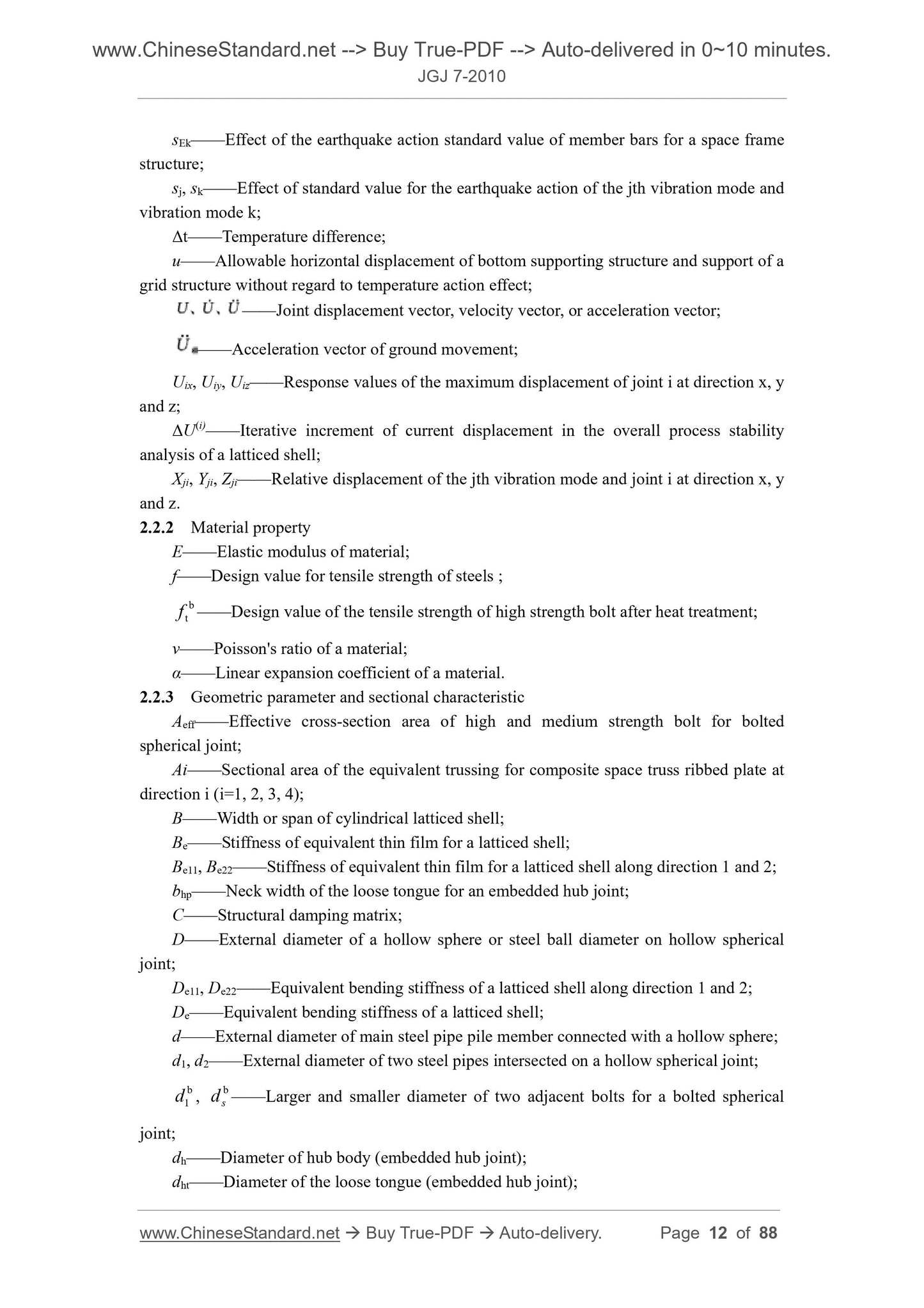
sEk——Effect of the earthquake action standard value of member bars for a space frame
structure;
sj, sk——Effect of standard value for the earthquake action of the jth vibration mode and
vibration mode k;
Δt——Temperature difference;
u——Allowable horizontal displacement of bottom supporting structure and support of a
grid structure without regard to temperature action effect;
——Joint displacement vector, velocity vector, or acceleration vector;
——Acceleration vector of ground movement;
Uix, Uiy, Uiz——Response values of the maximum displacement of joint i at direction x, y
and z;
ΔU(i)——Iterative increment of current displacement in the overall process stability
analysis of a latticed shell;
Xji, Yji, Zji——Relative displacement of the jth vibration mode and joint i at direction x, y
and z.
2.2.2 Material property
E——Elastic modulus of material;
f——Design value for tensile strength of steels ;
btf ——Design value of the tensile strength of high strength bolt after heat treatme...
Get QUOTATION in 1-minute: Click JGJ 7-2010
Historical versions: JGJ 7-2010
Preview True-PDF (Reload/Scroll if blank)
JGJ 7-2010: Technical specification for space frame structures
JGJ 7-2010
UDC JGJ
INDUSTRY STANDARD OF THE
PEOPLE’S REPUBLIC OF CHINA
P JGJ 7-2010
Filing Number. J 1072-2010
Technical Specification for Space Frame Structures
Issued on July 20, 2010 Implemented on March 1, 2011
Issued by. Ministry of Housing and Urban-Rural Construction of the People’s
Republic of China
Table of Contents
1 General Provisions ... 8
2 Terms and Symbols ... 9
2.1 Terms ... 9
2.2 Symbols ... 10
3 Basic Requirements ... 15
3.1 Structure Types ... 15
3.2 General Design Requirements for Space Trusses ... 15
3.3 General Design Requirements for Latticed Shells ... 17
3.4 General Design Requirements for Spatial Trusses, Arches and Beam String
Structures ... 18
3.5 Allowable Deflection ... 19
4 Structural Analysis ... 20
4.1 General Principles of Analysis ... 20
4.2 Static Analysis ... 21
4.3 Stability Analysis of Latticed Shells ... 23
4.4 Calculation due to Earthquake ... 24
5 Design and Details of Members and Joints ... 28
5.1 Members ... 28
5.2 Welded Hollow Spherical Joints ... 29
5.3 Bolted Spherical Joints ... 33
5.4 Embedded Hub Joints ... 37
5.5 Cast Steel Joints ... 39
5.6 Pin Joints ... 39
5.7 Joints of Composite Structures ... 40
5.8 Joints of Prestressed Cable ... 41
5.9 Supporting Joints ... 43
6 Fabrication, Erection and Acceptance ... 49
6.1 General Requirements ... 49
6.2 Requirements for Fabrication and Assembly ... 50
6.3 Assembly Elements in the Air ... 53
6.4 Erection by Strips or Blocks ... 54
6.5 Assembly by Sliding ... 55
6.6 Integral Hoisting by Derrick Masts or Cranes ... 56
6.7 Integral Lifting-up ... 58
6.8 Integral Jacking-up ... 58
6.9 Fold and Unfold Methods ... 59
6.10 Construction of Composite Space Trusses ... 60
6.11 Checking and Acceptance ... 60
Appendix A Types of Space Truss Commonly Used ... 62
Appendix B Types of Latticed Shell Commonly Used ... 65
Appendix C Equivalent Stiffness of Latticed Shells ... 67
Appendix D Simplified Method of Analysis for Composite Space Trusses ... 69
Appendix E Formula of Stability Capacity for Latticed Shells ... 71
Appendix F Formula of Multidimensional Response Spectrum ... 73
Appendix G Simplified Calculation of the Effect due to Vertical Earthquake for Roof
Trusses ... 75
Appendix H Coefficient of Forces of Latticed Shells under Horizontal Earthquake ... 77
Appendix J Formula of Primary Dimensions of Embedded Hub Joints ... 80
Appendix K Material Behavior and Details Requirements of Elastomeric Bearing Pad ... 83
Explanation of Wording in This Specification ... 87
List of Quoted Standards ... 88
1 General Provisions
1.0.1 This standard is formulated with a view to implementing the national technical and
economic policies in the design and construction of space frame structure and making the
design to be of advanced technology, safety and usability, economy and rationality and high
quality.
1.0.2 This standard is applicable to the design and construction of space frame structure
composed of steel members, including space truss, single layer or double-layer latticed shell
and spatial truss.
1.0.3 In the design of space frame structure, the reasonable structure scheme, frame/grid
layout and structure measures shall be selected according to the actual situation and the
comprehensive consideration shall be taken for material supply, processing fabrication and
onsite construction, to ensure better technical and economic effects.
1.0.4 Suspended crane shall not be arranged for single-layer latticed shell structure. Space
truss and double-layer latticed shell structures may directly withstand the suspended crane
load at Level A3 or higher level. In case the cycle times of the stress variation is larger than or
equal to 5×10⁴, the fatigue analysis shall be conducted, and the allowable stress amplitude and
the structure shall be determined by special test.
1.0.5 The design and construction of space frame structure shall comply with the
requirements in the current relevant national standards besides this standard.
2 Terms and Symbols
2.1 Terms
2.1.1 Space grid structure, space frame, space latticed structure
Spatial structure formed of member and member bar arranged in a certain rule by joint
connection, including space truss, curved latticed shell and spatial truss
2.1.2 Space truss, space grid
Flat plate type or slight curved spatial trussing structure formed of member bars arranged
in a certain rule by joint connection, mainly bearing the integral bending internal force
2.1.3 Intersecting lattice truss system
System formed of two-way or three-way intersecting lattice trusses
2.1.4 Square pyramid system
System formed of square pyramids as basic unit
2.1.5 Triangular pyramid system
System formed of triangular pyramids as basic unit
2.1.6 Composite space truss
Flat lattice truss structure formed by reinforced concrete slab as upper chord member and
steel web member and bottom chord bar
2.1.7 Latticed shell, reticulated shell
Curved spatial trussing structure or beam structure formed of member bars arranged in a
certain rule by joint connection, mainly bearing the integral thin film internal force
2.1.8 Spherical latticed shell, braced dome
Single-layer or double-layer latticed shell structure with spherical appearance
2.1.9 Cylindrical latticed shell, braced vault
Single-layer or double-layer latticed shell structure with cylindric surface appearance
2.1.10 Hyperbolic paraboloid latticed shell
Single-layer or double-layer latticed shell structure with the appearance of hyperbolic
paraboloid
2.1.11 Elliptic paraboloid latticed shell
Single-layer or double-layer latticed shell structure with the appearance of elliptic
paraboloid
2.1.12 Lamella grid
Rhombic grid cell formed of two-way heterotopic member bars
2.1.13 Ribbed type
Trapezia grid cell formed of radial and circumferential member bar on spherical face
2.1.14 Ribbed type with diagonal bars (Schwedler dome)
Triangular grid cell formed of radial, circumferential and diagonal member on spherical
face
2.1.15 Three-way grid
Equilateral triangle grid cell formed of three-way member bars
2.1.16 Fan shape three-way grid (Kiewitt dome)
Triangular grid cell formed of circumferential member bar jointly with the lamella grid
formed of parallel rods in n (n=6, 8) sector curved surfaces divided radially on a spherical
face
sEk——Effect of the earthquake action standard value of member bars for a space frame
structure;
sj, sk——Effect of standard value for the earthquake action of the jth vibration mode and
vibration mode k;
Δt——Temperature difference;
u——Allowable horizontal displacement of bottom supporting structure and support of a
grid structure without regard to temperature action effect;
——Joint displacement vector, velocity vector, or acceleration vector;
——Acceleration vector of ground movement;
Uix, Uiy, Uiz——Response values of the maximum displacement of joint i at direction x, y
and z;
ΔU(i)——Iterative increment of current displacement in the overall process stability
analysis of a latticed shell;
Xji, Yji, Zji——Relative displacement of the jth vibration mode and joint i at direction x, y
and z.
2.2.2 Material property
E——Elastic modulus of material;
f——Design value for tensile strength of steels ;
btf ——Design value of the tensile strength of high strength bolt after heat treatme...
Share