1
/
de
11
PayPal, credit cards. Download editable-PDF & invoice in 1 second!
YY/T 0935-2014 English PDF (YYT0935-2014)
YY/T 0935-2014 English PDF (YYT0935-2014)
Prix habituel
$145.00 USD
Prix habituel
Prix promotionnel
$145.00 USD
Prix unitaire
/
par
Frais d'expédition calculés à l'étape de paiement.
Impossible de charger la disponibilité du service de retrait
Delivery: 3 seconds. Download true-PDF + Invoice.
Get QUOTATION in 1-minute: Click YY/T 0935-2014
Historical versions: YY/T 0935-2014
Preview True-PDF (Reload/Scroll if blank)
YY/T 0935-2014: Particular specifications for CT injector
YY/T 0935-2014
YY
PHARMACEUTICAL INDUSTRY STANDARD
OF THE PEOPLE’S REPUBLIC OF CHINA
ICS 11.040.50
C 43
Particular specifications for CT injector
[Including 2020XG1 Amendment 1]
ISSUED ON: JUNE 17, 2014
IMPLEMENTED ON: JULY 1, 2015
Issued by: China Food and Drug Administration
Table of Contents
Foreword ... 3
1 Scope ... 4
2 Normative references ... 4
3 Terms and definitions ... 4
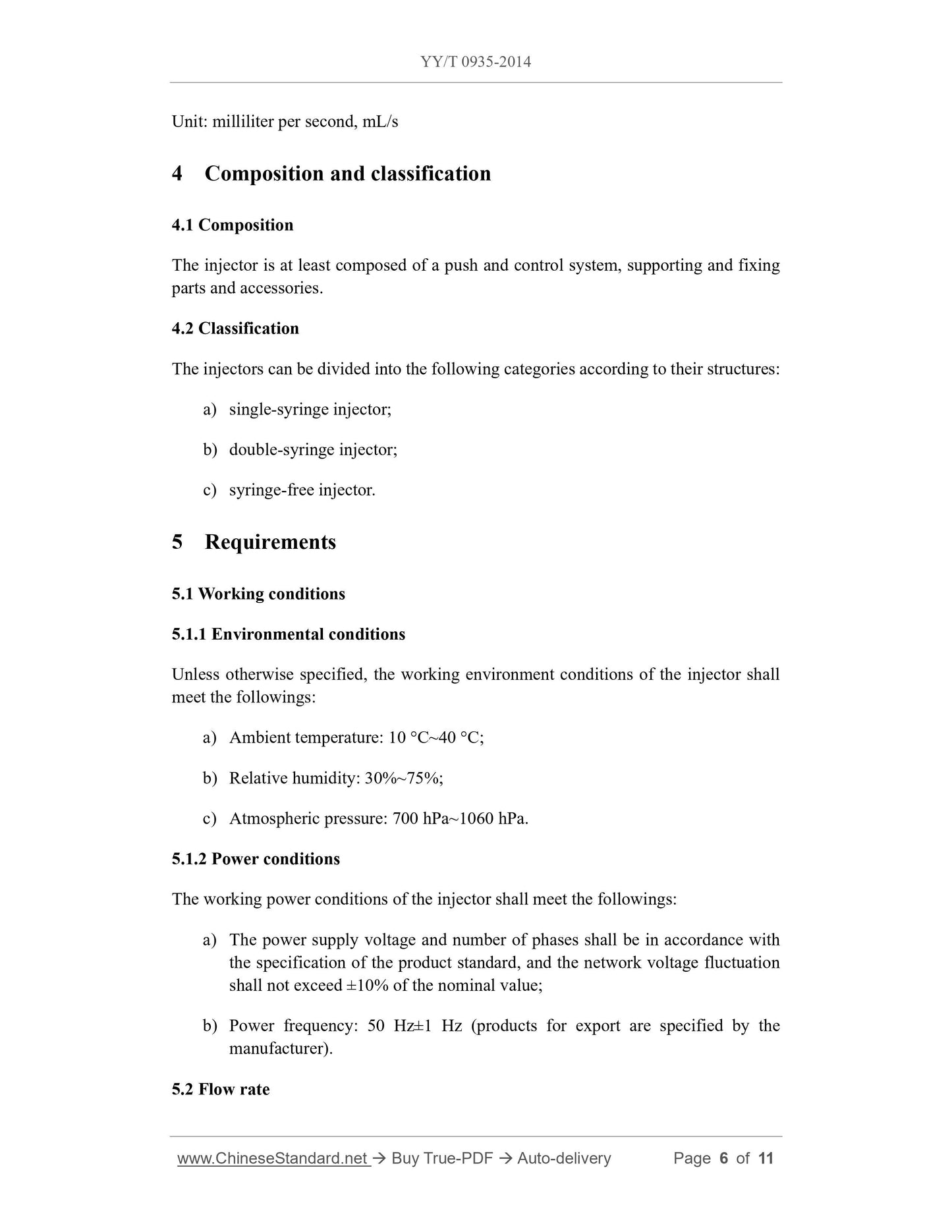
4 Composition and classification ... 6
5 Requirements ... 6
6 Test methods ... 8
2020XG1 Amendment 1 ... 11
Particular specifications for CT injector
1 Scope
This standard specifies the terms and definitions, classification and composition,
requirements, and test methods of CT (X-ray computed tomography) injectors
(hereinafter referred to as injectors).
This standard applies to injectors. This standard does not involve accessories such as
disposable syringes specially used for injectors.
2 Normative references
The following documents are essential to the application of this document. For the dated
referenced documents, only the versions with the indicated dates are applicable to this
document; for the undated referenced documents, only the latest version (including all
the amendments) is applicable to this document.
GB 9706.1-2007 Medical electrical equipment - Part 1: General requirements for
safety
GB 9706.15-2008 Medical electrical equipment - Part 1: General requirements for
safety - 1. Collateral standard: Safety requirements for medical electrical systems
GB/T 10149-1988 Terminology and symbol for medical X-ray equipment
GB/T 14710-2009 Environmental requirement and test methods for medical
electrical equipment
YY 0076-1992 Coating classifications for metal product - Technical conditions
YY 0505-2012 Medical electrical equipment - Part 1-2: General requirements for
safety - Collateral standard: Electromagnetic Compatibility - Requirements and
tests
YY/T 0708-2009 Medical electrical equipment - Part 1-4: General requirements
for safety - Collateral standard: Programmable electrical medical systems
3 Terms and definitions
The terms and definitions defined in GB/T 10149-1988 and the followings apply to this
document.
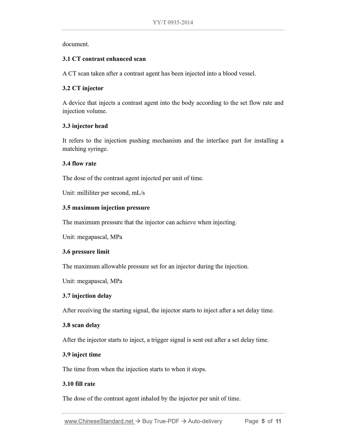
3.1 CT contrast enhanced scan
A CT scan taken after a contrast agent has been injected into a blood vessel.
3.2 CT injector
A device that injects a contrast agent into the body according to the set flow rate and
injection volume.
3.3 injector head
It refers to the injection pushing mechanism and the interface part for installing a
matching syringe.
3.4 flow rate
The dose of the contrast agent injected per unit of time.
Unit: milliliter per second, mL/s
3.5 maximum injection pressure
The maximum pressure that the injector can achieve when injecting.
Unit: megapascal, MPa
3.6 pressure limit
The maximum allowable pressure set for an injector during the injection.
Unit: megapascal, MPa
3.7 injection delay
After receiving the starting signal, the injector starts to inject after a set delay time.
3.8 scan delay
After the injector starts to inject, a trigger signal is sent out after a set delay time.
3.9 inject time
The time from when the injection starts to when it stops.
3.10 fill rate
The dose of the contrast agent inhaled by the injector per unit of time.
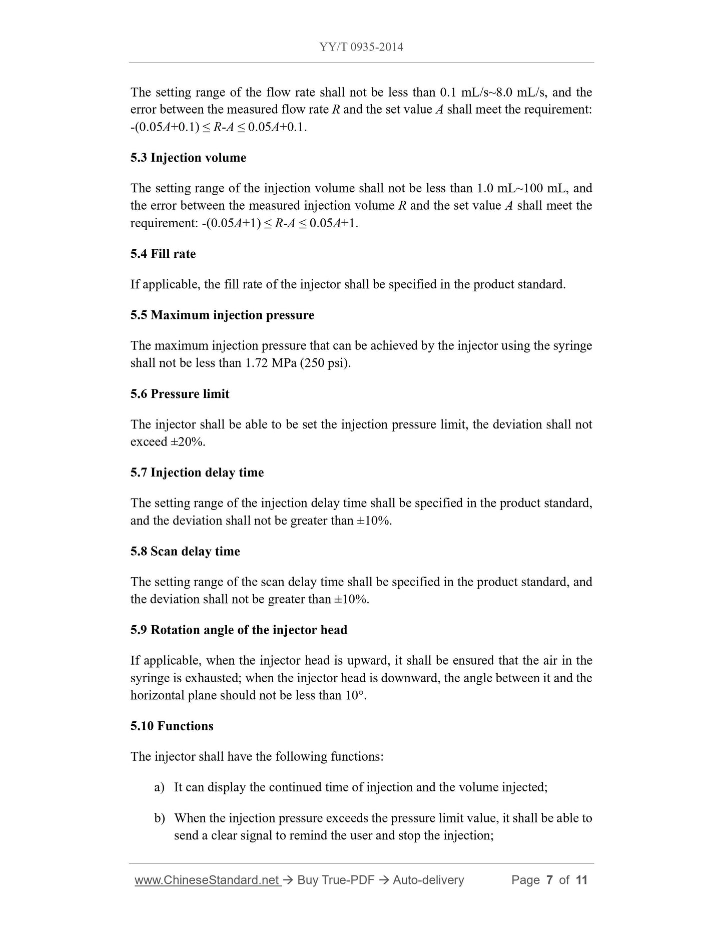
The setting range of the flow rate shall not be less than 0.1 mL/s~8.0 mL/s, and the
error between the measured flow rate R and the set value A shall meet the requirement:
-(0.05A+0.1) ≤ R-A ≤ 0.05A+0.1.
5.3 Injection volume
The setting range of the injection volume shall not be less than 1.0 mL~100 mL, and
the error between the measured injection volume R and the set value A shall meet the
requirement: -(0.05A+1) ≤ R-A ≤ 0.05A+1.
5.4 Fill rate
If applicable, the fill rate of the injector shall be specified in the product standard.
5.5 Maximum injection pressure
The maximum injection pressure that can be achieved by the injector using the syringe
shall not be less than 1.72 MPa (250 psi).
5.6 Pressure limit
The injector shall be able to be set the injection pressure limit, the deviation shall not
exceed ±20%.
5.7 Injection delay time
The setting range of the injection delay time shall be specified in the product standard,
and the deviation shall not be greater than ±10%.
5.8 Scan delay time
The setting range of the scan delay time shall be specified in the product standard, and
the deviation shall not be greater than ±10%.
5.9 Rotation angle of the injector head
If applicable, when the injector head is upward, it shall be ensured that the air in the
syringe is exhausted; when the injector head is downward, the angle between it and the
horizontal plane should not be less than 10°.
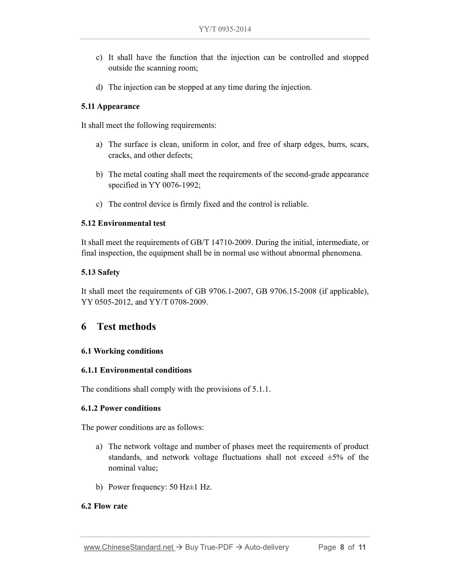
5.10 Functions
The injector shall have the following functions:
a) It can display the continued time of injection and the volume injected;
b) When the injection pressure exceeds the pressure limit value, it shall be able to
send a clear signal to remind the user and stop the injection;
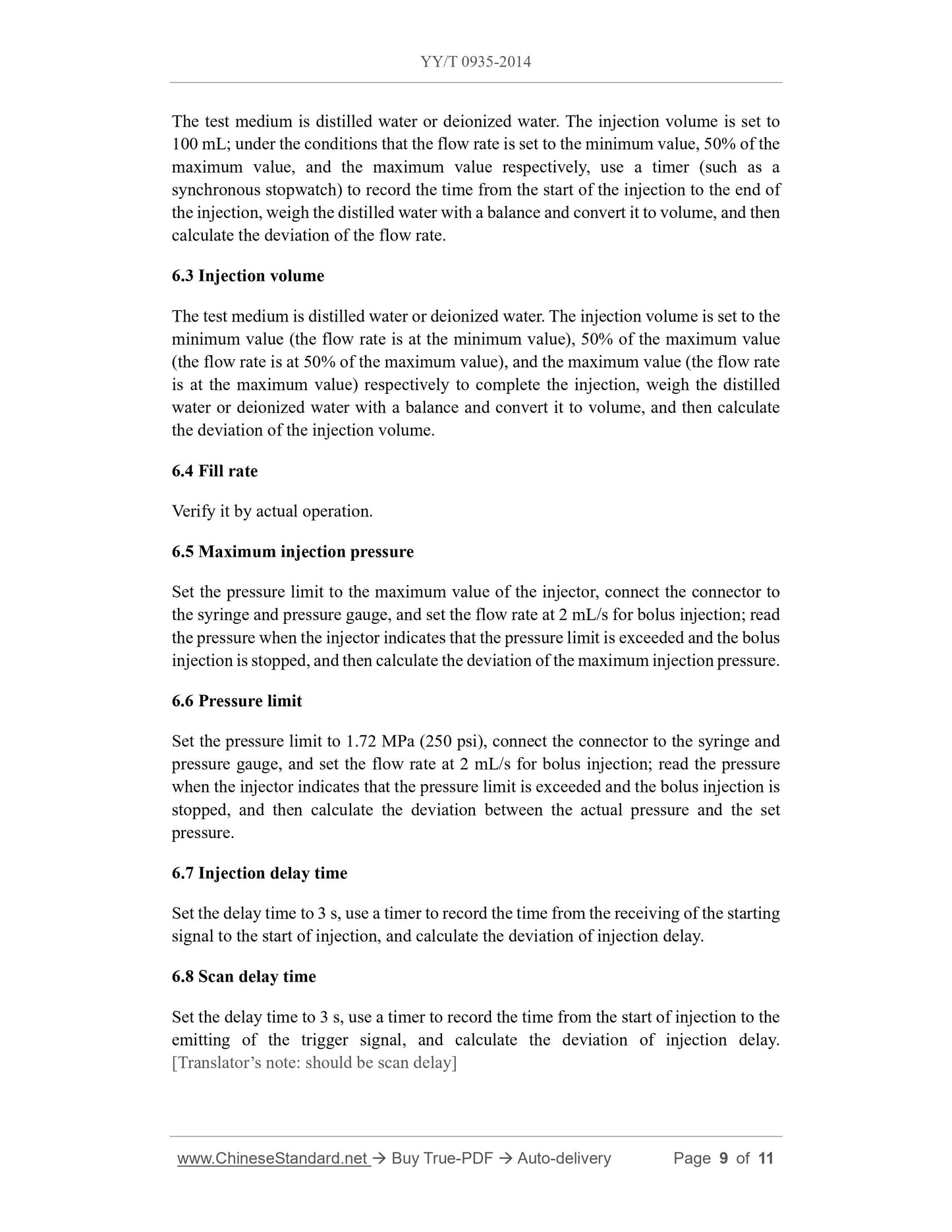
The test medium is distilled water or deionized water. The injection volume is set to
100 mL; under the conditions that the flow rate is set to the minimum value, 50% of the
maximum value, and the maximum value respectively, use a timer (such as a
synchronous stopwatch) to record the time from the start of the injection to the end of
the injection, weigh the distilled water with a balance and convert it to volume, and then
calculate the deviation of the flow rate.
6.3 Injection volume
The test medium is distilled water or deionized water. The injection volume is set to the
minimum value (the flow rate is at the minimum value), 50% of the maximum value
(the flow rate is at 50% of the maximum value), and the maximum value (the flow rate
is at the maximum value) respectively to complete the injection, weigh the distilled
water or deionized water with a balance and convert it to volume, and then calculate
the deviation of the injection volume.
6.4 Fill rate
Verify it by actual operation.
6.5 Maximum injection pressure
Set the pressure limit to the maximum value of the injector, connect the connector to
the syringe and pressure gauge, and set the flow rate at 2 mL/s for bolus injection; read
the pressure when the injector indicates that the pressure limit is exceeded and the bolus
injection is stopped, and then calculate the deviation of the maximum injection pressure.
6.6 Pressure limit
Set the pressure limit to 1.72 MPa (250 psi), connect the connector to the syringe and
pressure gauge, and set the flow rate at 2 mL/s for bolus injection; read the pressure
when the injector indicates that the pressure limit is exceeded and the bolus injection is
stopped, and then calculate the deviation between the actual pressure and the set
pressure.
6.7 Injection delay time
Set the delay time to 3 s, use a timer to record the time from the receiving of the starting
signal to the start of injection, and calculate the deviation of injection delay.
6.8 Scan delay time
Set the delay time to 3 s, use a timer to record the time from the start of injection to the
emitting of the trigger signal, and calculate the deviation of injection delay.
[Translator’s note: should be scan delay]
Get QUOTATION in 1-minute: Click YY/T 0935-2014
Historical versions: YY/T 0935-2014
Preview True-PDF (Reload/Scroll if blank)
YY/T 0935-2014: Particular specifications for CT injector
YY/T 0935-2014
YY
PHARMACEUTICAL INDUSTRY STANDARD
OF THE PEOPLE’S REPUBLIC OF CHINA
ICS 11.040.50
C 43
Particular specifications for CT injector
[Including 2020XG1 Amendment 1]
ISSUED ON: JUNE 17, 2014
IMPLEMENTED ON: JULY 1, 2015
Issued by: China Food and Drug Administration
Table of Contents
Foreword ... 3
1 Scope ... 4
2 Normative references ... 4
3 Terms and definitions ... 4
4 Composition and classification ... 6
5 Requirements ... 6
6 Test methods ... 8
2020XG1 Amendment 1 ... 11
Particular specifications for CT injector
1 Scope
This standard specifies the terms and definitions, classification and composition,
requirements, and test methods of CT (X-ray computed tomography) injectors
(hereinafter referred to as injectors).
This standard applies to injectors. This standard does not involve accessories such as
disposable syringes specially used for injectors.
2 Normative references
The following documents are essential to the application of this document. For the dated
referenced documents, only the versions with the indicated dates are applicable to this
document; for the undated referenced documents, only the latest version (including all
the amendments) is applicable to this document.
GB 9706.1-2007 Medical electrical equipment - Part 1: General requirements for
safety
GB 9706.15-2008 Medical electrical equipment - Part 1: General requirements for
safety - 1. Collateral standard: Safety requirements for medical electrical systems
GB/T 10149-1988 Terminology and symbol for medical X-ray equipment
GB/T 14710-2009 Environmental requirement and test methods for medical
electrical equipment
YY 0076-1992 Coating classifications for metal product - Technical conditions
YY 0505-2012 Medical electrical equipment - Part 1-2: General requirements for
safety - Collateral standard: Electromagnetic Compatibility - Requirements and
tests
YY/T 0708-2009 Medical electrical equipment - Part 1-4: General requirements
for safety - Collateral standard: Programmable electrical medical systems
3 Terms and definitions
The terms and definitions defined in GB/T 10149-1988 and the followings apply to this
document.
3.1 CT contrast enhanced scan
A CT scan taken after a contrast agent has been injected into a blood vessel.
3.2 CT injector
A device that injects a contrast agent into the body according to the set flow rate and
injection volume.
3.3 injector head
It refers to the injection pushing mechanism and the interface part for installing a
matching syringe.
3.4 flow rate
The dose of the contrast agent injected per unit of time.
Unit: milliliter per second, mL/s
3.5 maximum injection pressure
The maximum pressure that the injector can achieve when injecting.
Unit: megapascal, MPa
3.6 pressure limit
The maximum allowable pressure set for an injector during the injection.
Unit: megapascal, MPa
3.7 injection delay
After receiving the starting signal, the injector starts to inject after a set delay time.
3.8 scan delay
After the injector starts to inject, a trigger signal is sent out after a set delay time.
3.9 inject time
The time from when the injection starts to when it stops.
3.10 fill rate
The dose of the contrast agent inhaled by the injector per unit of time.
The setting range of the flow rate shall not be less than 0.1 mL/s~8.0 mL/s, and the
error between the measured flow rate R and the set value A shall meet the requirement:
-(0.05A+0.1) ≤ R-A ≤ 0.05A+0.1.
5.3 Injection volume
The setting range of the injection volume shall not be less than 1.0 mL~100 mL, and
the error between the measured injection volume R and the set value A shall meet the
requirement: -(0.05A+1) ≤ R-A ≤ 0.05A+1.
5.4 Fill rate
If applicable, the fill rate of the injector shall be specified in the product standard.
5.5 Maximum injection pressure
The maximum injection pressure that can be achieved by the injector using the syringe
shall not be less than 1.72 MPa (250 psi).
5.6 Pressure limit
The injector shall be able to be set the injection pressure limit, the deviation shall not
exceed ±20%.
5.7 Injection delay time
The setting range of the injection delay time shall be specified in the product standard,
and the deviation shall not be greater than ±10%.
5.8 Scan delay time
The setting range of the scan delay time shall be specified in the product standard, and
the deviation shall not be greater than ±10%.
5.9 Rotation angle of the injector head
If applicable, when the injector head is upward, it shall be ensured that the air in the
syringe is exhausted; when the injector head is downward, the angle between it and the
horizontal plane should not be less than 10°.
5.10 Functions
The injector shall have the following functions:
a) It can display the continued time of injection and the volume injected;
b) When the injection pressure exceeds the pressure limit value, it shall be able to
send a clear signal to remind the user and stop the injection;
The test medium is distilled water or deionized water. The injection volume is set to
100 mL; under the conditions that the flow rate is set to the minimum value, 50% of the
maximum value, and the maximum value respectively, use a timer (such as a
synchronous stopwatch) to record the time from the start of the injection to the end of
the injection, weigh the distilled water with a balance and convert it to volume, and then
calculate the deviation of the flow rate.
6.3 Injection volume
The test medium is distilled water or deionized water. The injection volume is set to the
minimum value (the flow rate is at the minimum value), 50% of the maximum value
(the flow rate is at 50% of the maximum value), and the maximum value (the flow rate
is at the maximum value) respectively to complete the injection, weigh the distilled
water or deionized water with a balance and convert it to volume, and then calculate
the deviation of the injection volume.
6.4 Fill rate
Verify it by actual operation.
6.5 Maximum injection pressure
Set the pressure limit to the maximum value of the injector, connect the connector to
the syringe and pressure gauge, and set the flow rate at 2 mL/s for bolus injection; read
the pressure when the injector indicates that the pressure limit is exceeded and the bolus
injection is stopped, and then calculate the deviation of the maximum injection pressure.
6.6 Pressure limit
Set the pressure limit to 1.72 MPa (250 psi), connect the connector to the syringe and
pressure gauge, and set the flow rate at 2 mL/s for bolus injection; read the pressure
when the injector indicates that the pressure limit is exceeded and the bolus injection is
stopped, and then calculate the deviation between the actual pressure and the set
pressure.
6.7 Injection delay time
Set the delay time to 3 s, use a timer to record the time from the receiving of the starting
signal to the start of injection, and calculate the deviation of injection delay.
6.8 Scan delay time
Set the delay time to 3 s, use a timer to record the time from the start of injection to the
emitting of the trigger signal, and calculate the deviation of injection delay.
[Translator’s note: should be scan delay]
Share