1
/
su
9
Sales@ChineseStandard.net (Field Test Asia Pte. Ltd.)
DL/T 911-2016 English PDF (DLT911-2016)
DL/T 911-2016 English PDF (DLT911-2016)
Prezzo di listino
$215.00 USD
Prezzo di listino
Prezzo scontato
$215.00 USD
Prezzo unitario
/
per
Spese di spedizione calcolate al check-out.
Impossibile caricare la disponibilità di ritiro
Delivery: 3 seconds. Download true-PDF + Invoice.
Get QUOTATION in 1-minute: Click DL/T 911-2016
Historical versions: DL/T 911-2016
Preview True-PDF (Reload/Scroll if blank)
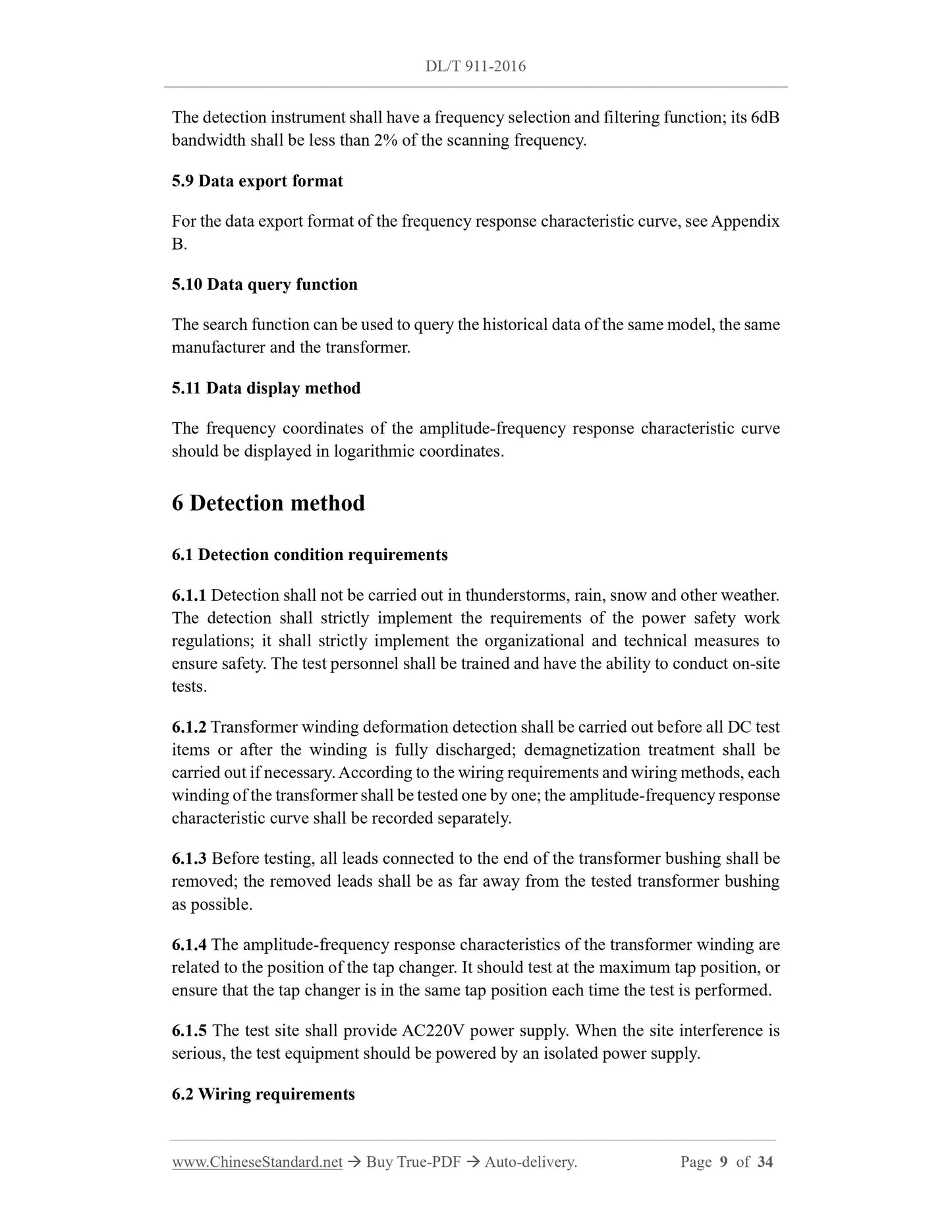
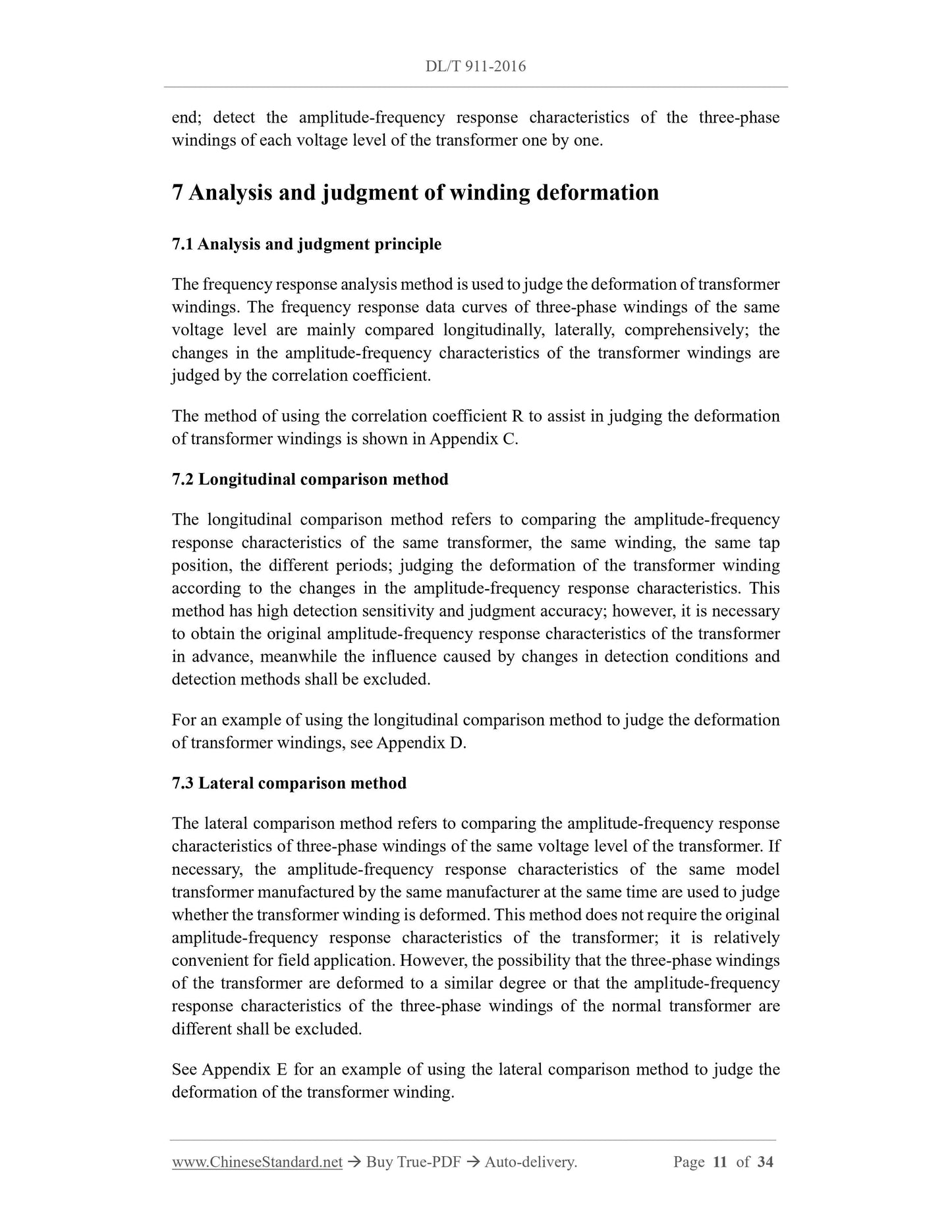
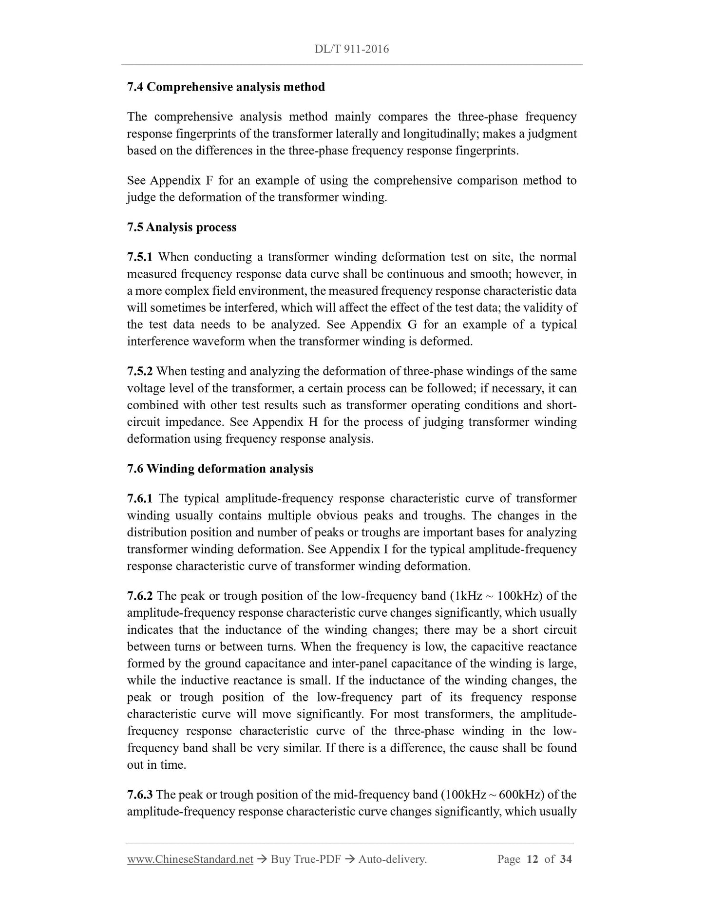
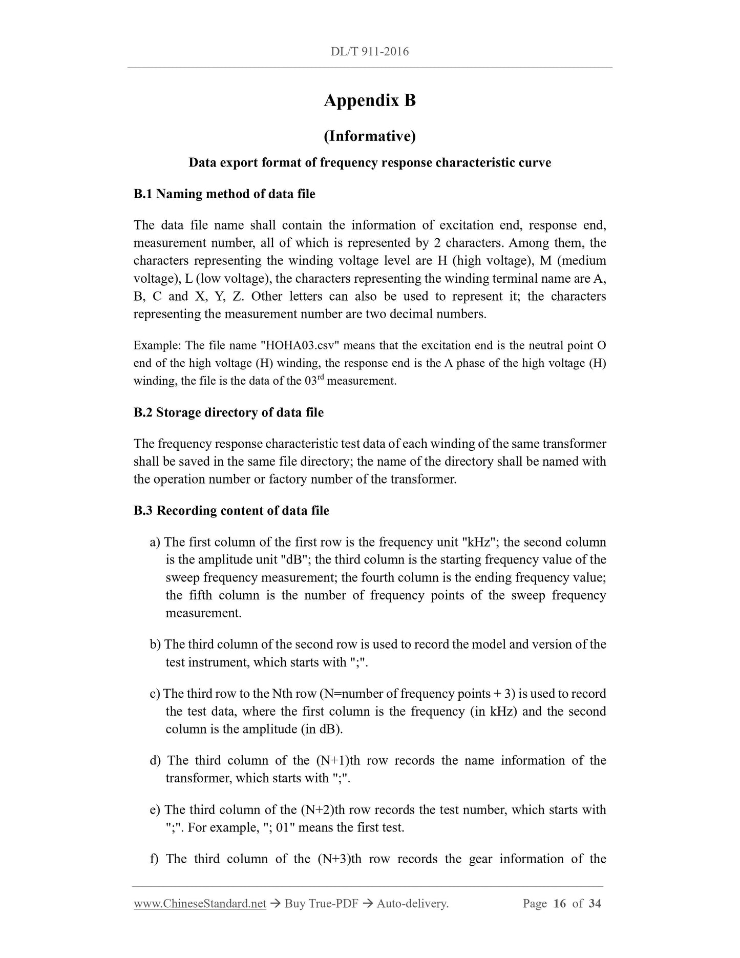
DL/T 911-2016: Frequency response analysis on winding deformation of power transformers
DL/T 911-2016
DL
ELECTRICITY INDUSTRY STANDARD
OF THE PEOPLE’S REPUBLIC OF CHINA
ICS 27.100
F 24
Filing No.: 53992-2016
Replacing DL/T 911-2004
Frequency response analysis on winding deformation of
power transformers
ISSUED ON: FEBRUARY 05, 2016
IMPLEMENTED ON: JULY 01, 2016
Issued by: National Energy Administration
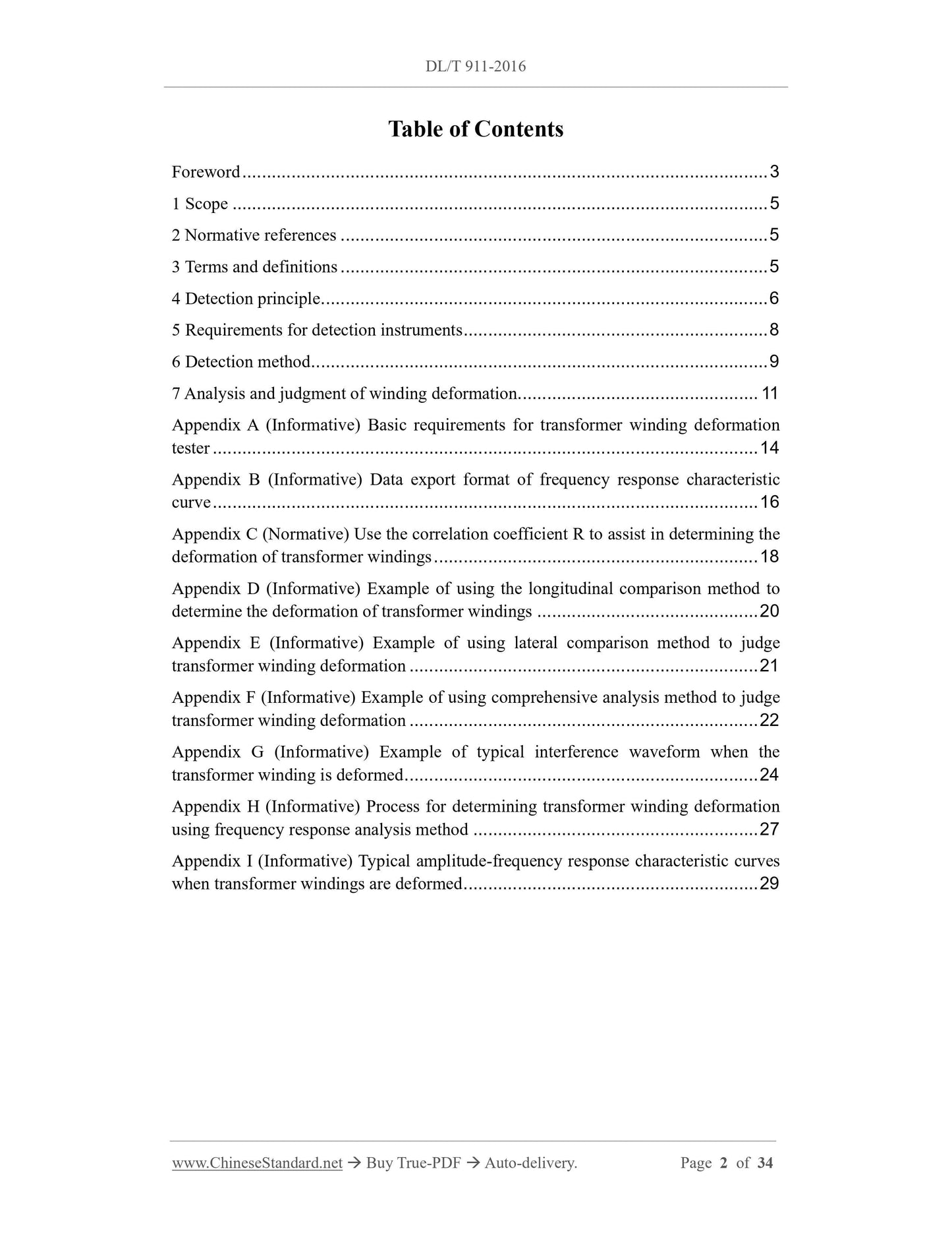
Table of Contents
Foreword ... 3
1 Scope ... 5
2 Normative references ... 5
3 Terms and definitions ... 5
4 Detection principle ... 6
5 Requirements for detection instruments ... 8
6 Detection method ... 9
7 Analysis and judgment of winding deformation ... 11
Appendix A (Informative) Basic requirements for transformer winding deformation
tester ... 14
Appendix B (Informative) Data export format of frequency response characteristic
curve ... 16
Appendix C (Normative) Use the correlation coefficient R to assist in determining the
deformation of transformer windings ... 18
Appendix D (Informative) Example of using the longitudinal comparison method to
determine the deformation of transformer windings ... 20
Appendix E (Informative) Example of using lateral comparison method to judge
transformer winding deformation ... 21
Appendix F (Informative) Example of using comprehensive analysis method to judge
transformer winding deformation ... 22
Appendix G (Informative) Example of typical interference waveform when the
transformer winding is deformed ... 24
Appendix H (Informative) Process for determining transformer winding deformation
using frequency response analysis method ... 27
Appendix I (Informative) Typical amplitude-frequency response characteristic curves
when transformer windings are deformed ... 29
Frequency response analysis on winding deformation of
power transformers
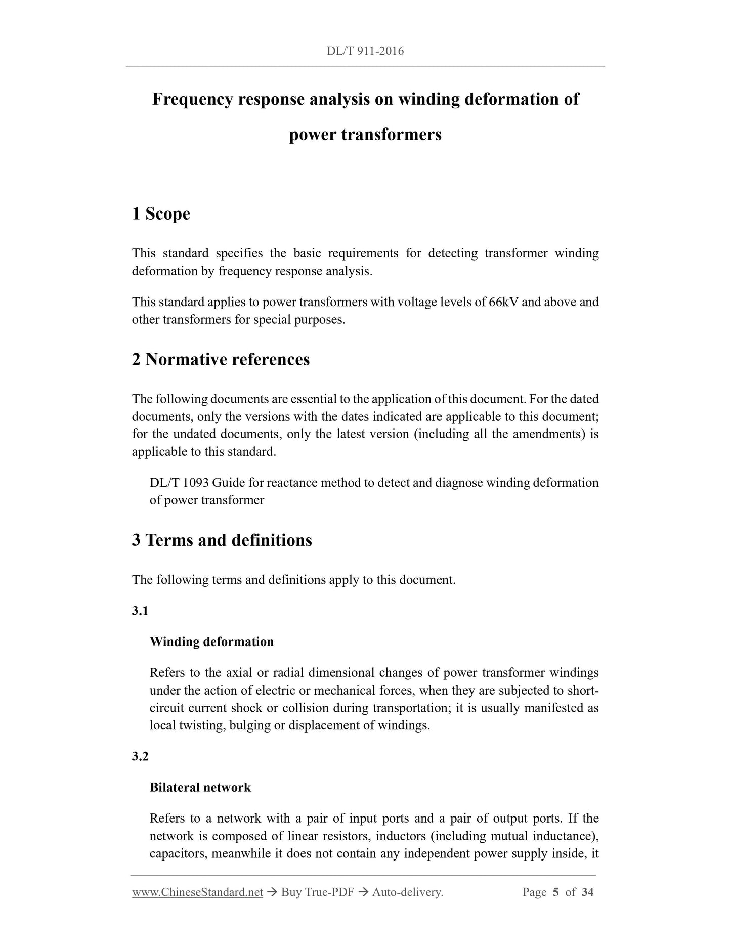
1 Scope
This standard specifies the basic requirements for detecting transformer winding
deformation by frequency response analysis.
This standard applies to power transformers with voltage levels of 66kV and above and
other transformers for special purposes.
2 Normative references
The following documents are essential to the application of this document. For the dated
documents, only the versions with the dates indicated are applicable to this document;
for the undated documents, only the latest version (including all the amendments) is
applicable to this standard.
DL/T 1093 Guide for reactance method to detect and diagnose winding deformation
of power transformer
3 Terms and definitions
The following terms and definitions apply to this document.
3.1
Winding deformation
Refers to the axial or radial dimensional changes of power transformer windings
under the action of electric or mechanical forces, when they are subjected to short-
circuit current shock or collision during transportation; it is usually manifested as
local twisting, bulging or displacement of windings.
3.2
Bilateral network
Refers to a network with a pair of input ports and a pair of output ports. If the
network is composed of linear resistors, inductors (including mutual inductance),
capacitors, meanwhile it does not contain any independent power supply inside, it
H(f) - Modulus |H(jω)| of transfer function at frequency f;
U2(f), U1(f) - Peak or effective value of voltage |U₂(jω)| and |U₁(jω)| at response end
and excitation end at frequency f.
5 Requirements for detection instruments
5.1 Basic requirements for detection instruments
For the basic requirements of transformer winding deformation tester, please refer to
Appendix A.
5.2 Sweep frequency detection range
The sweep frequency detection range shall include the frequency band of 1kHz ~
1000kHz.
5.3 Sweep frequency detection method
It should adopt linear distribution frequency sweep detection method; repeat detection
of single frequency point can be performed.
5.4 Sweep frequency accuracy
The frequency accuracy of the sine wave signal output by the signal source shall not
exceed 0.01%.
5.5 Scanning frequency interval
The scanning frequency interval should be 1kHz.
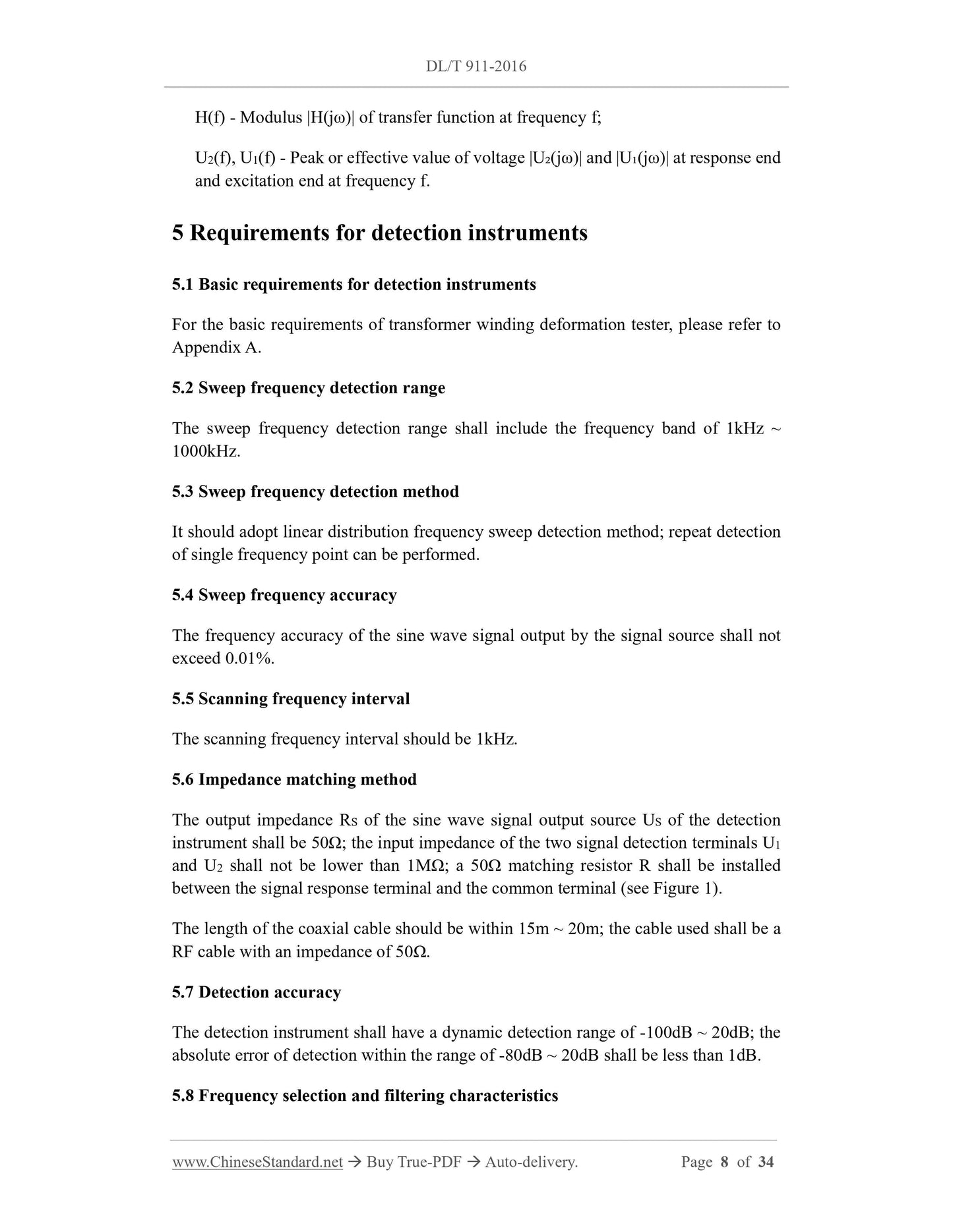
5.6 Impedance matching method
The output impedance RS of the sine wave signal output source US of the detection
instrument shall be 50Ω; the input impedance of the two signal detection terminals U1
and U2 shall not be lower than 1MΩ; a 50Ω matching resistor R shall be installed
between the signal response terminal and the common terminal (see Figure 1).
The length of the coaxial cable should be within 15m ~ 20m; the cable used shall be a
RF cable with an impedance of 50Ω.
5.7 Detection accuracy
The detection instrument shall have a dynamic detection range of -100dB ~ 20dB; the
absolute error of detection within the range of -80dB ~ 20dB shall be less than 1dB.
5.8 Frequency selection and filtering characteristics
The detection instrument shall have a frequency selection and filtering function; its 6dB
bandwidth shall be less than 2% of the scanning frequency.
5.9 Data export format
For the data export format of the frequency response characteristic curve, see Appendix
B.
5.10 Data query function
The search function can be used to query the historical data of the same model, the same
manufacturer and the transformer.
5.11 Data display method
The frequency coordinates of the amplitude-frequency response characteristic curve
should be displayed in logarithmic coordinates.
6 Detection method
6.1 Detection condition requirements
6.1.1 Detection shall not be carried out in thunderstorms, rain, snow and other weather.
The detection shall strictly implement the requirements of the power safety work
regulations; it shall strictly implement the organizational and technical measures to
ensure safety. The test personnel shall be trained and have the ability to conduct on-site
tests.
6.1.2 Transformer winding deformation detection shall be carried out before all DC test
items or after the winding is fully discharged; demagnetization treatment shall be
carried out if necessary. According to the wiring requirements and wiring methods, each
winding of the transformer shall be tested one by one; the amplitude-frequency response
characteristic curve shall be recorded separately.
6.1.3 Before testing, all leads connected to the end of the transformer bushing shall be
removed; the removed leads shall be as far away from the tested transformer bushing
as possible.
6.1.4 The amplitude-frequency response characteristics of the transformer winding are
related to the position of the tap changer. It should test at the maximum tap position, or
ensure that the tap changer is in the same tap position each time the test is performed.
6.1.5 The test site shall provide AC220V power supply. When the site interference is
serious, the test equipment should be powered by an isolated power supply.
6.2 Wiring requirements
end; detect the amplitude-frequency response characteristics of the three-phase
windings of each voltage level of the transformer one by one.
7 Analysis and judgment of winding deformation
7.1 Analysis and judgment principle
The frequency response analysis method is used to judge the deformation of transformer
windings. The frequency response data curves of three-phase windings of the same
voltage level are mainly compared longitudinally, laterally, comprehensively; the
changes in the amplitude-frequency characteristics of the transformer windings are
judged by the correlation coefficient.
The method of using the correlation coefficie...
Share
