1
/
su
12
PayPal, credit cards. Download editable-PDF and invoice in 1 second!
GB 14167-2024 English PDF (GB14167-2024)
GB 14167-2024 English PDF (GB14167-2024)
Prezzo di listino
$606.00 USD
Prezzo di listino
Prezzo scontato
$606.00 USD
Prezzo unitario
/
per
Spese di spedizione calcolate al check-out.
Impossibile caricare la disponibilità di ritiro
Delivery: 3 seconds. Download true-PDF + Invoice.
Get QUOTATION in 1-minute: Click GB 14167-2024
Historical versions: GB 14167-2024
Preview True-PDF (Reload/Scroll if blank)
GB 14167-2024: Safety-belt anchorages and restraint systems anchorages for occupants of power-driven vehicles
GB 14167-2024
GB
NATIONAL STANDARD OF THE
PEOPLE’S REPUBLIC OF CHINA
ICS 43.040.60
CCS T 26
Replacing GB 14167-2013
Safety-belt Anchorages and Restraint Systems Anchorages
for Occupants of Power-driven Vehicles
ISSUED ON. SEPTEMBER 29, 2024
IMPLEMENTED ON. JULY 1, 2025
Issued by. State Administration for Market Regulation;
Standardization Administration of the People’s Republic of China.
Table of Contents
Foreword... 3
1 Scope... 5
2 Normative References... 5
3 Terms and Definitions... 6
4 Technical Requirements... 9
5 Test Methods... 21
6 Determination of the Same Type... 27
7 Implementation of the Standard... 28
Appendix A (normative) ISOFIX Anchorages System, ISOFIX Top Tether Anchorages
and i-Size Seating Positions... 30
Appendix B (normative) Minimum Quantity of Anchorages... 47
Appendix C (normative) Position of Effective Anchorages... 48
Appendix D (normative) Schematic Diagram of Human Body Module... 51
Appendix E (normative) Dynamic Test---Alternative Test for Static Test... 53
Appendix F (normative) Dummy Specifications... 55
Appendix G (normative) Static Force Application Device with Support Leg Test Rod
... 56
Safety-belt Anchorages and Restraint Systems Anchorages
for Occupants of Power-driven Vehicles
1 Scope
This document specifies the technical requirements for the safety-belt anchorages and restraint
systems anchorages for occupants of power-driven vehicles and describes the test methods and
determination of the same type.
This document is applicable to the following vehicles.
---Category-M and Category-N vehicles equipped with safety-belt anchorages for adult
occupants of forward-facing, rear-facing or side-facing seats;
---Category-M1 vehicles equipped with ISOFIX anchorages system for child restraint
system and their top tether anchorage, and other categories of vehicles equipped with
ISOFIX anchorages system;
---Vehicles with i-Size seating position.
2 Normative References
The contents of the following documents constitute indispensable clauses of this document
through the normative references in the text. In terms of references with a specified date, only
versions with a specified date are applicable to this document. In terms of references without a
specified date, the latest version (including all the modifications) is applicable to this document.
GB 11551-2014 The Protection of the Occupants in the Event of a Frontal Collision for Motor
Vehicle
GB 11552-2009 The Interior Fittings of Passenger Car
GB 13057 The Strength of the Seats and Their Anchorages of Passenger Vehicles
GB 13094-2017 The Safety Requirements for Bus Construction
GB 14166-2024 Safety-belts and Restraint Systems for Occupants of Power-driven Vehicles
GB 27887 Restraining Devices for Child Occupants of Power-driven Vehicles
GB/T 29120 Procedure for H-point and R-point Determination
ISO 6487 Road Vehicles - Measurement Techniques in Impact Tests - Instrumentation
2) The included angle between the template torso line and the transverse vertical
plane is the same as the angle between the seat back when it is in its most upright
position;
3) The template is placed on the longitudinal vertical plane passing through the
point H.
c) As shown in Figure A.11, the ISOFIX low anchorage is installed in the ISOFIX
position. Utilize the fixture ISO/F2 alternative method of Figure A.5 in GB 14166-
2024 to determine the position of the top tether anchorage. The seating position shall
be with the seat adjusted to the rearmost and lowest position, and the seat back in the
normal position or the position recommended by the manufacturer. In the side view,
the ISOFIX top tether anchorage shall be behind the ISO/F2 rear surface. The
intersection point of the ISO/F2 rear surface and the horizontal line passing through
the last rigid point of the top of the seat backrest with a Shore A hardness exceeding
50 (Figure A.11) and the ISO/F2 center line is determined as datum point 4.At this
point, the maximum 45 upward from the horizontal line is defined as the upper limit
of the top tether anchorage area. In the top view, make an area with a maximum angle
of 90 through datum point 4 to both sides of the back. In the rear view, make an area
with a maximum angle of 40 through datum point 4.The ISOFIX top tether
anchorage is located in the two three-dimensional areas. The starting point 5 of the
ISOFIX top tether strap is located at the intersection of a plane 550 mm upward from
plane 1 of the ISO/F2 fixture and the center line 6.Measure along the strap from the
seat back to the ISOFIX top tether anchorage, and the distance between the ISOFIX
top tether anchorage and the starting point of the ISOFIX top tether strap on the rear
surface of the ISO/F2 fixture shall be greater than 200 mm, but not greater than 2,000
mm.
d) If the ISOFIX top tether anchorage cannot be placed within the specified shadow area
and the vehicle is equipped with an ISOFIX top tether anchorage path guidance device,
then, the ISOFIX top tether anchorage of the vehicle connected to the ISOFIX top
tether strap connector may exceed the shadow area specified in 4.1.4 b) or 4.1.4 c).
Meanwhile, the ISOFIX top tether anchorage path guidance device shall satisfy.
1) The ISOFIX top tether strap shall have equivalent functionality to the fixtures
located within the shadow area and used to connect the ISOFIX top tether
anchorage;
2) The non-rigid webbing type path guidance device or extensible path guidance
device shall be no less than 65 mm away from the torso line, and the fixed rigid
path guidance device shall be no less than 100 mm away from the torso line;
3) After being installed in the state of usage, carry out the tests in accordance with
the ISOFIX top tether anchorage loading specified in 5.6, and the device shall
satisfy the requirements of 4.5.4.
e) If the top tether anchorage device is not within the strap winding area at the top of the
seat back, it is allowed to be hidden on the seat back.
f) The ISOFIX top tether anchorage shall satisfy the connection size requirements of the
ISOFIX top tether hook specified in Figure A.3.Space shall be provided around each
ISOFIX top tether anchorage to allow its locking and unlocking operations. All
anchorages located behind any ISOFIX anchorages system that can be used to connect
the ISOFIX top tether hook or ISOFIX top tether strap connector shall adopt one or
more of the following measures to avoid misuse.
1) Design all such anchorages within the ISOFIX top tether anchorage area as
ISOFIX top tether anchorages;
2) Only use one of the symbols shown in Figure A.13 or its mirror image symbol
to identify the ISOFIX top tether anchorages;
3) For the identification of anchorages that do not satisfy the requirements of 4.1.4
f) 1) and 4.1.4 f) 2), it shall be clearly stated that these anchorages cannot be
combined with any ISOFIX anchorages system.
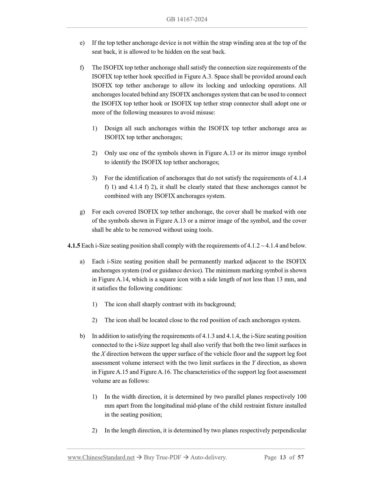
g) For each covered ISOFIX top tether anchorage, the cover shall be marked with one
of the symbols shown in Figure A.13 or a mirror image of the symbol, and the cover
shall be able to be removed without using tools.
4.1.5 Each i-Size seating position shall comply with the requirements of 4.1.2 ~ 4.1.4 and below.
a) Each i-Size seating position shall be permanently marked adjacent to the ISOFIX
anchorages system (rod or guidance device). The minimum marking symbol is shown
in Figure A.14, which is a square icon with a side length of not less than 13 mm, a...
Share
