1
/
の
8
PayPal, credit cards. Download editable-PDF and invoice in 1 second!
DB35/T 1968-2021 English PDF (DB35T1968-2021)
DB35/T 1968-2021 English PDF (DB35T1968-2021)
通常価格
$190.00 USD
通常価格
セール価格
$190.00 USD
単価
/
あたり
配送料はチェックアウト時に計算されます。
受取状況を読み込めませんでした
Delivery: 3 seconds. Download true-PDF + Invoice.
Get QUOTATION in 1-minute: Click DB35/T 1968-2021
Historical versions: DB35/T 1968-2021
Preview True-PDF (Reload/Scroll if blank)
DB35/T 1968-2021: The scene measuring methods of LED panels
DB35/T 1968-2021
DB35
LOCAL STANDARD OF THE FUJIAN PROVINCE
ICS 31.120
CCS L 63
The scene measuring methods of LED panels
ISSUED ON. FEBRUARY 9, 2021
IMPLEMENTED ON. MAY 9, 2021
Issued by. Fujian Market Supervision and Administration Bureau
Table of Contents
Foreword... 3
1 Scope... 4
2 Normative references... 4
3 Terms and definitions... 4
4 General requirements... 4
5 Measurement methods... 5
6 Reports and records... 13
The scene measuring methods of LED panels
1 Scope
This document specifies the field measurement methods for the electrical and optical
characteristics of LED displays.
This document applies to field measurements of Light Emitting Diode (LED) displays
installed in outdoor and indoor locations.
2 Normative references
The provisions of the following documents constitute the essential clauses of this
document through normative references in this text. Among them, for referenced
documents with dates, only the versions corresponding to the dates are applicable to
this document; for referenced documents without dates, the latest versions (including
all amendments) are applicable to this document.
GB/T 34973-2017 On-site measurements of obtrusive light of LED panels
SJ/T 11141-2017 Generic specification for LED displays
SJ/T 11281-2017 Measure methods of light emitting diode (LED) displays
SJ/T 11590-2016 A subjective method for the evaluation of the displaying quality
of LED displays
3 Terms and definitions
The terms and definitions defined in GB/T 34973-2017, SJ/T 11141-2017, SJ/T 11281-
2017 and SJ/T 11590-2016 apply to this document.
4 General requirements
4.1 Test conditions
When measuring, interference from environmental factors shall be avoided.
4.2 Measuring instruments
Luminance meter. not less than level 2;
Lux meter. not less than level 2;
Power analyzer. not less than Class 1.0;
Vernier caliper. with a resolution of not less than 0.02 mm;
Other length measuring tools. the accuracy is not less than 10 mm.
4.3 Samples
Unless otherwise specified, the electrical parameters of the LED display shall meet the
following conditions during measurement.
a) The deviation between the input voltage and the rated voltage is not greater
than 10%;
b) The input frequency is 50 Hz±1 Hz.
5 Measurement methods
5.1 Measurement method
5.1.1 Measurement conditions
The overall size of the LED display is measured when it is in the black screen state, and
the effective display size is measured when it is in the full light state.
5.1.2 Measurement steps
The measurement is performed in the following steps.
a) First, turn off the power supply, observe the shape of the LED display, such as
square, rectangle, and arc, and record the observation results;
b) Use length measuring tools to measure the overall size, installation height and
pixel pitch of the LED display;
c) Turn on the power supply, use the length measuring tool to measure the
effective display size of the LED display and calculate its area.
5.2 Subjective evaluation
5.2.1 Subjective evaluation
The observers shall be composed of persons with normal vision (including corrected
vision) and normal color discrimination ability (no color weakness or color blindness),
of different genders and ages, and the number shall be no less than 3.Other
light probe acquisition range shall not be less than 16 adjacent pixels.
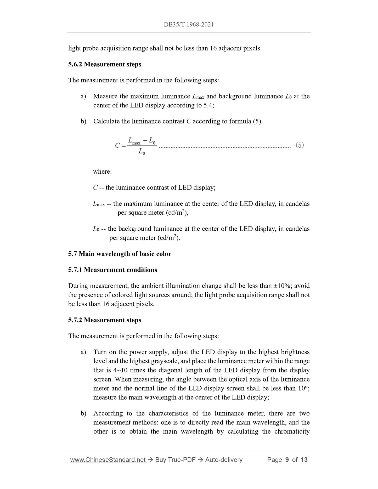
5.6.2 Measurement steps
The measurement is performed in the following steps.
a) Measure the maximum luminance Lmax and background luminance L0 at the
center of the LED display according to 5.4;
b) Calculate the luminance contrast C according to formula (5).
where.
C -- the luminance contrast of LED display;
Lmax -- the maximum luminance at the center of the LED display, in candelas
per square meter (cd/m2);
L0 -- the background luminance at the center of the LED display, in candelas
per square meter (cd/m2).
5.7 Main wavelength of basic color
5.7.1 Measurement conditions
During measurement, the ambient illumination change shall be less than ±10%; avoid
the presence of colored light sources around; the light probe acquisition range shall not
be less than 16 adjacent pixels.
5.7.2 Measurement steps
The measurement is performed in the following steps.
a) Turn on the power supply, adjust the LED display to the highest brightness
level and the highest grayscale, and place the luminance meter within the range
that is 4~10 times the diagonal length of the LED display from the display
screen. When measuring, the angle between the optical axis of the luminance
meter and the normal line of the LED display screen shall be less than 10°;
measure the main wavelength at the center of the LED display;
b) According to the characteristics of the luminance meter, there are two
measurement methods. one is to directly read the main wavelength, and the
other is to obtain the main wavelength by calculating the chromaticity
coordinates. The calculation method is based on the provisions of Article
5.2.4.4 of SJ/T 11281-2017.
5.8 Center point chromaticity (where applicable)
5.8.1 Measurement conditions
During measurement, the ambient illumination variation shall be less than ±10%; the
light probe acquisition range shall not be less than 16 adjacent pixels.
5.8.2 Measurement steps
Turn on the power supply, adjust the LED display to the highest brightness level and
the highest grayscale, display a full white image, and measure the chromaticity
coordinates and correlated color temperature of the center of the LED display using a
luminance meter within the range that is 4~10 times the diagonal length of the LED
display from the display screen. During measurement, the angle between the optical
axis of the luminance meter and the normal line of the LED display screen shall be less
than 10°.
5.9 Color uniformity
5.9.1 Measurement conditions
During measurement, the ambient illumination variation shall be less than ±10%; the
light probe acquisition range shall not be less than 16 adjacent pixels.
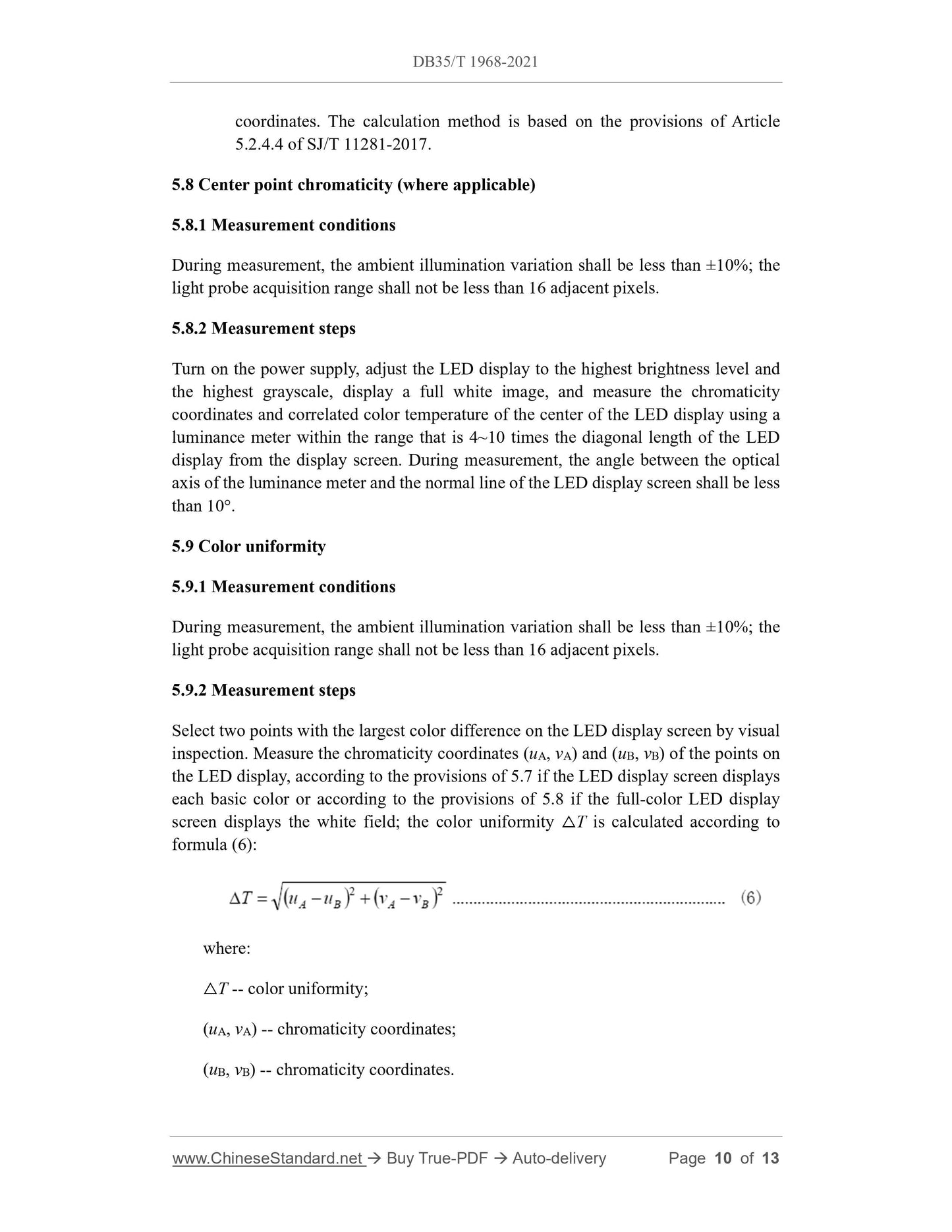
5.9.2 Measurement steps
Select two points with the largest color difference on the LED display screen by visual
inspection. Measure the chromaticity coordinates (uA, vA) and (uB, vB) of the points on
the LED display, according to the provisions of 5.7 if the LED display screen displays
each basic color or according to the provisions of 5.8 if the full-color LED display
screen displays the white field; the color uniformity △T is calculated according to
formula (6).
where.
△T -- color uniformity;
(uA, vA) -- chromaticity coordinates;
(uB, vB) -- chromaticity coordinates.
5.10 White balance error
5.10.1 Measurement conditions
During measurement, the ambient illumination variation shall be less than ±10%; the
light probe acquisition range shall not be less than 16 adjacent pixels.
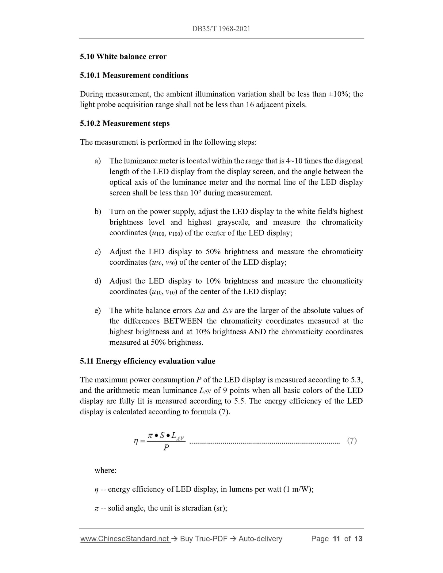
5.10.2 Measurement steps
The measurement is performed in the following steps.
a) The luminance meter is located within the range that is 4~10 times the diagonal
length of the LED display from the display screen, and the angle between the
optical axis of the luminance meter and the normal line of the LED display
screen shall be less than 10° during measurement.
b) Turn on the power supply, adjust the LED display to the white field's highest
brightn...
Get QUOTATION in 1-minute: Click DB35/T 1968-2021
Historical versions: DB35/T 1968-2021
Preview True-PDF (Reload/Scroll if blank)
DB35/T 1968-2021: The scene measuring methods of LED panels
DB35/T 1968-2021
DB35
LOCAL STANDARD OF THE FUJIAN PROVINCE
ICS 31.120
CCS L 63
The scene measuring methods of LED panels
ISSUED ON. FEBRUARY 9, 2021
IMPLEMENTED ON. MAY 9, 2021
Issued by. Fujian Market Supervision and Administration Bureau
Table of Contents
Foreword... 3
1 Scope... 4
2 Normative references... 4
3 Terms and definitions... 4
4 General requirements... 4
5 Measurement methods... 5
6 Reports and records... 13
The scene measuring methods of LED panels
1 Scope
This document specifies the field measurement methods for the electrical and optical
characteristics of LED displays.
This document applies to field measurements of Light Emitting Diode (LED) displays
installed in outdoor and indoor locations.
2 Normative references
The provisions of the following documents constitute the essential clauses of this
document through normative references in this text. Among them, for referenced
documents with dates, only the versions corresponding to the dates are applicable to
this document; for referenced documents without dates, the latest versions (including
all amendments) are applicable to this document.
GB/T 34973-2017 On-site measurements of obtrusive light of LED panels
SJ/T 11141-2017 Generic specification for LED displays
SJ/T 11281-2017 Measure methods of light emitting diode (LED) displays
SJ/T 11590-2016 A subjective method for the evaluation of the displaying quality
of LED displays
3 Terms and definitions
The terms and definitions defined in GB/T 34973-2017, SJ/T 11141-2017, SJ/T 11281-
2017 and SJ/T 11590-2016 apply to this document.
4 General requirements
4.1 Test conditions
When measuring, interference from environmental factors shall be avoided.
4.2 Measuring instruments
Luminance meter. not less than level 2;
Lux meter. not less than level 2;
Power analyzer. not less than Class 1.0;
Vernier caliper. with a resolution of not less than 0.02 mm;
Other length measuring tools. the accuracy is not less than 10 mm.
4.3 Samples
Unless otherwise specified, the electrical parameters of the LED display shall meet the
following conditions during measurement.
a) The deviation between the input voltage and the rated voltage is not greater
than 10%;
b) The input frequency is 50 Hz±1 Hz.
5 Measurement methods
5.1 Measurement method
5.1.1 Measurement conditions
The overall size of the LED display is measured when it is in the black screen state, and
the effective display size is measured when it is in the full light state.
5.1.2 Measurement steps
The measurement is performed in the following steps.
a) First, turn off the power supply, observe the shape of the LED display, such as
square, rectangle, and arc, and record the observation results;
b) Use length measuring tools to measure the overall size, installation height and
pixel pitch of the LED display;
c) Turn on the power supply, use the length measuring tool to measure the
effective display size of the LED display and calculate its area.
5.2 Subjective evaluation
5.2.1 Subjective evaluation
The observers shall be composed of persons with normal vision (including corrected
vision) and normal color discrimination ability (no color weakness or color blindness),
of different genders and ages, and the number shall be no less than 3.Other
light probe acquisition range shall not be less than 16 adjacent pixels.
5.6.2 Measurement steps
The measurement is performed in the following steps.
a) Measure the maximum luminance Lmax and background luminance L0 at the
center of the LED display according to 5.4;
b) Calculate the luminance contrast C according to formula (5).
where.
C -- the luminance contrast of LED display;
Lmax -- the maximum luminance at the center of the LED display, in candelas
per square meter (cd/m2);
L0 -- the background luminance at the center of the LED display, in candelas
per square meter (cd/m2).
5.7 Main wavelength of basic color
5.7.1 Measurement conditions
During measurement, the ambient illumination change shall be less than ±10%; avoid
the presence of colored light sources around; the light probe acquisition range shall not
be less than 16 adjacent pixels.
5.7.2 Measurement steps
The measurement is performed in the following steps.
a) Turn on the power supply, adjust the LED display to the highest brightness
level and the highest grayscale, and place the luminance meter within the range
that is 4~10 times the diagonal length of the LED display from the display
screen. When measuring, the angle between the optical axis of the luminance
meter and the normal line of the LED display screen shall be less than 10°;
measure the main wavelength at the center of the LED display;
b) According to the characteristics of the luminance meter, there are two
measurement methods. one is to directly read the main wavelength, and the
other is to obtain the main wavelength by calculating the chromaticity
coordinates. The calculation method is based on the provisions of Article
5.2.4.4 of SJ/T 11281-2017.
5.8 Center point chromaticity (where applicable)
5.8.1 Measurement conditions
During measurement, the ambient illumination variation shall be less than ±10%; the
light probe acquisition range shall not be less than 16 adjacent pixels.
5.8.2 Measurement steps
Turn on the power supply, adjust the LED display to the highest brightness level and
the highest grayscale, display a full white image, and measure the chromaticity
coordinates and correlated color temperature of the center of the LED display using a
luminance meter within the range that is 4~10 times the diagonal length of the LED
display from the display screen. During measurement, the angle between the optical
axis of the luminance meter and the normal line of the LED display screen shall be less
than 10°.
5.9 Color uniformity
5.9.1 Measurement conditions
During measurement, the ambient illumination variation shall be less than ±10%; the
light probe acquisition range shall not be less than 16 adjacent pixels.
5.9.2 Measurement steps
Select two points with the largest color difference on the LED display screen by visual
inspection. Measure the chromaticity coordinates (uA, vA) and (uB, vB) of the points on
the LED display, according to the provisions of 5.7 if the LED display screen displays
each basic color or according to the provisions of 5.8 if the full-color LED display
screen displays the white field; the color uniformity △T is calculated according to
formula (6).
where.
△T -- color uniformity;
(uA, vA) -- chromaticity coordinates;
(uB, vB) -- chromaticity coordinates.
5.10 White balance error
5.10.1 Measurement conditions
During measurement, the ambient illumination variation shall be less than ±10%; the
light probe acquisition range shall not be less than 16 adjacent pixels.
5.10.2 Measurement steps
The measurement is performed in the following steps.
a) The luminance meter is located within the range that is 4~10 times the diagonal
length of the LED display from the display screen, and the angle between the
optical axis of the luminance meter and the normal line of the LED display
screen shall be less than 10° during measurement.
b) Turn on the power supply, adjust the LED display to the white field's highest
brightn...
Share