1
/
の
10
PayPal, credit cards. Download editable-PDF and invoice in 1 second!
DL/T 259-2012 English PDF (DLT259-2012)
DL/T 259-2012 English PDF (DLT259-2012)
通常価格
$145.00 USD
通常価格
セール価格
$145.00 USD
単価
/
あたり
配送料はチェックアウト時に計算されます。
受取状況を読み込めませんでした
Delivery: 3 seconds. Download true-PDF + Invoice.
Get QUOTATION in 1-minute: Click DL/T 259-2012
Historical versions: DL/T 259-2012
Preview True-PDF (Reload/Scroll if blank)
DL/T 259-2012: Calibration regulation for SF6 gas density monitor
DL/T 259-2012
DL
ELECTRIC POWER INDUSTRY STANDARD
OF THE PEOPLE’S REPUBLIC OF CHINA
ICS 29.120.70
K 33
Filing No.. 36413-2012
Calibration regulation for SF6 gas density relay
ISSUED ON. APRIL 6, 2012
IMPLEMENTED ON. JULY 1, 2012
Issued by. National Energy Administration
Table of Contents
Foreword ... 3
1 Scope ... 4
2 Normative references ... 4
3 Terms and definitions ... 4
4 General technical requirements ... 6
5 Metrological property requirements ... 10
6 Calibration conditions ... 11
7 Calibration method ... 13
8 Calibration standard, cycle and items ... 16
Annex A (Normative) Test process ... 18
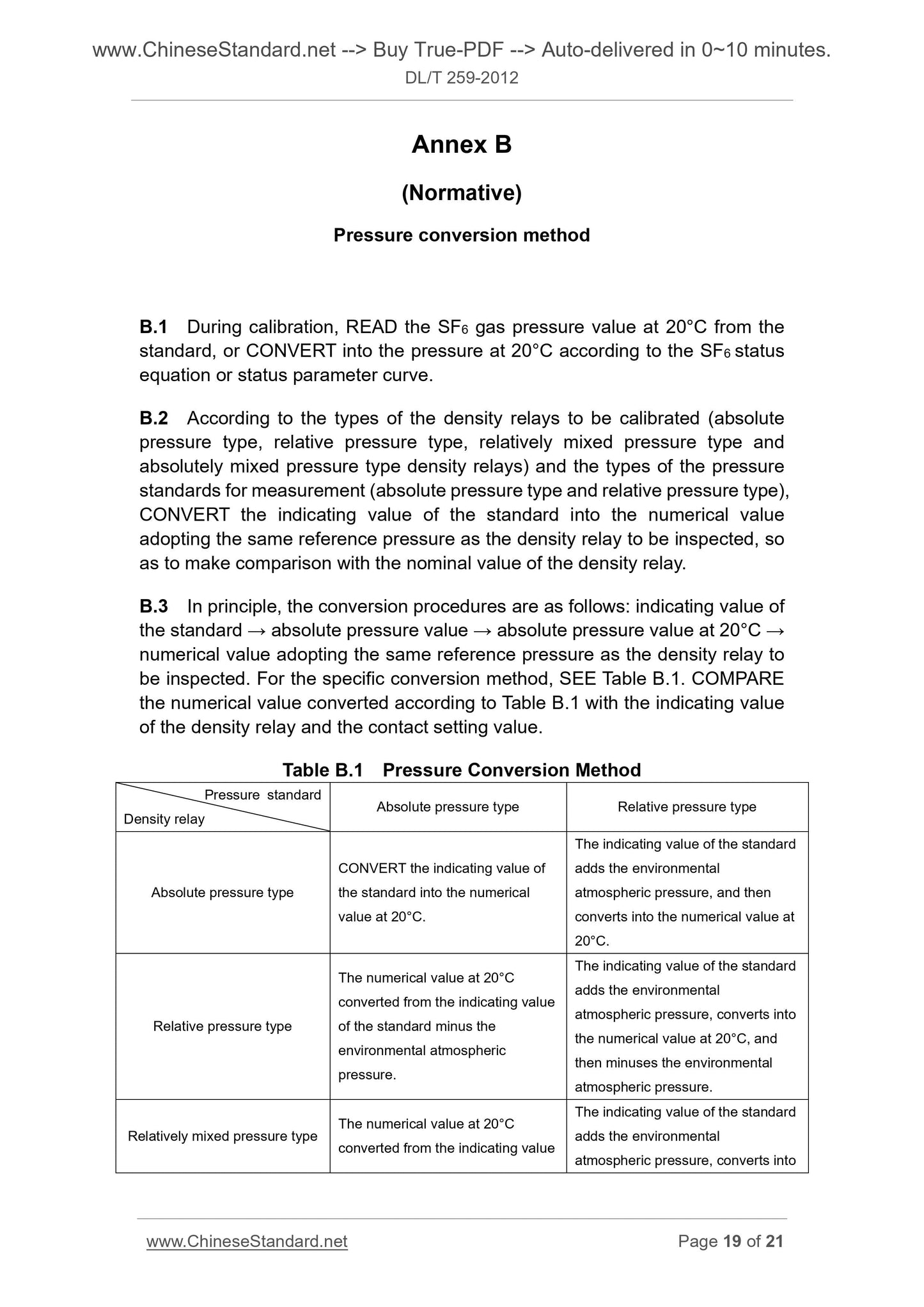
Annex B (Normative) Pressure conversion method ... 19
Annex C (Informative) SF6 gas status equation ... 21
Calibration regulation for SF6 gas density relay
1 Scope
This Standard specifies the general technical requirements, metrological
property requirements, calibration items and calibration methods of the spring
tube type SF6 gas density relays (hereinafter referred to as “density relays”).
This Standard is applicable to the on-site calibration and laboratory calibration
of the spring tube type SF6 gas density relays newly produced, in use and after
repair. Other types of SF6 gas density relays can be calibrated by reference to
this Standard.
2 Normative references
The following documents are essential to the application of this Standard. For
dated references, only the editions with the dates indicated are applicable to
this Standard. For undated references, only the latest editions (including all the
amendments) are applicable to this Standard.
GB/T 2423.10 Environmental testing for electric and electronic products -
Part 2. Test methods - Test Fc. Vibration (sinusoidal) (GB/T 2423.10-2008,
IEC 60068-2-6. 1995, IDT)
GB/T 11287 Electrical relays - Part 21. Vibration, shock, bump and seismic
tests on measuring relays and protection equipment - Section one. Vibration
tests (sinusoidal) (GB/T 11287-2000, IEC 255-21-1.1988, IDT)
GB/T 22065-2008 Pressure type SF6 gas density monitor
DL/T 393 Regulations of condition-based maintenance and test for electric
equipment
3 Terms and definitions
The terms and definitions defined in DL/T 393-2010 and the following ones are
applicable to this Standard.
3.1 Rating pressure
It refers to the pressure of filling the equipment air chamber with the required
SF6 gas under standard atmospheric conditions, before the equipment is put
into operation or during air injection.
3.2 Alarm pressure
It refers to the pressure of giving alarm signals, when the SF6 gas pressure in
the equipment air chamber drops to a certain set value.
3.3 Lock pressure
It refers to the pressure of giving lock signals, when the SF6 gas pressure in the
equipment air chamber drops to a certain set value.
3.4 Overpressure alarm pressure
It refers to the pressure of giving overpressure alarm signals, when the SF6 gas
pressure in the equipment air chamber rises to a certain set value exceeding
the rating pressure.
3.5 Absolute pressure type density relay
It refers to the gas density relay indicated with absolute pressure and using
absolute vacuum as reference pressure.
3.6 Relative pressure type density relay
It refers to the gas density relay indicated with relative pressure and using
environmental atmospheric pressure as reference pressure.
3.7 Relatively mixed pressure type density relay
It refers to the gas density relay indicated with relative pressure and using
standard atmospheric pressure as reference pressure.
3.8 Absolutely mixed pressure type density relay
It refers to the gas density relay indicated with absolute pressure and using
environmental atmospheric pressure as reference pressure.
3.9 Condition-based maintenance
It refers to a kind of maintenance strategy used for arranging the maintenance
reasonably, based on the equipment status and taking the security, reliability,
environment, cost and other factors into overall consideration.
[Definition 3.1.1 in DL/T 393-2010]
4.2.1 As for the density relay equipped with a stop pin, whose scale starts
from a certain positive pressure value, when the ambient temperature is 20°C
and the atmospheric pressure is standard atmospheric pressure, the pointer
shall rest against the limit nail under non-pressure working condition, before the
pressure-rise calibration and after the pressure-drop calibration. For the specific
relationships among reference zero, temperature and atmospheric pressure,
REFER to the instruction manual of this density relay.
4.2.2 As for the density relay whose scale starts from the minimum pressure
value, the pointer zero error under non-pressure working condition, before the
pressure-rise calibration and after the pressure-drop calibration, shall comply
with the following requirements.
a) For the absolute pressure type density relays, when the ambient temperature
is 20°C, the pointers shall point at local atmospheric pressure value. When
the ambient temperature is higher than 20°C, the pointers shall point at the
pressure which is lower than local atmospheric pressure. When the ambient
temperature is lower than 20°C, the pointers shall point at the pressure which
is higher than local atmospheric pressure. For the specific relationships
among reference zero, temperature and atmospheric pressure, REFER to
the instruction manual of the density relays.
b) For the relative pressure type density relays, when the ambient temperature
is 20°C, the pointers shall point within the width range of the zero index line.
The width of the zero index line shall not exceed twice the absolute value of
the maximum allowable basic error. When the ambient temperature is higher
than 20°C, the pointers shall point at the position below the zero. When the
ambient temperature is lower than 20°C, the pointers shall point at the
position above the zero. For the specific relationship between reference zero
and temperature, REFER to the instruction manual of the density relays.
c) For the relatively mixed pressure type density relays, when the ambient
temperature is 20°C, the pointers shall point at the difference of local
environmental atmospheric pressure minus standard atmospheric pressure.
When the ambient temperature is higher than 20°C, the pointers shall point
at the position below this difference. When the ambient temperature is lower
than 20°C, the pointers shall point at the position above this difference. For
the specific relationship between reference zero and temperature, REFER to
the instruction manual of the density relays.
d) For the absolutely mixed pressure type density relays, when the ambient
temperature is 20°C, the pointers shall point within the width range of the
0.1MPa index line. The width of the index line shall not exceed twice the
absolute value of the maximum allowable basic error. When the ambient
temperature is higher than 20°C, the pointers shall point at the position below
Under rating pressure, the hysteresis error shall not be greater than the
permissible error specified in Section 5.1.
5.4 Tapping displacement
TAP the case so that the pointer can swing freely. The variation of the pointer’s
indicating value shall not be greater than 1/2 of the absolute value of the
permissible error specified in Section 5.1.
5.5 Pointer deflection stability
Within the range of measurement, the pointer deflection shall be stable and
without obvious ...
Get QUOTATION in 1-minute: Click DL/T 259-2012
Historical versions: DL/T 259-2012
Preview True-PDF (Reload/Scroll if blank)
DL/T 259-2012: Calibration regulation for SF6 gas density monitor
DL/T 259-2012
DL
ELECTRIC POWER INDUSTRY STANDARD
OF THE PEOPLE’S REPUBLIC OF CHINA
ICS 29.120.70
K 33
Filing No.. 36413-2012
Calibration regulation for SF6 gas density relay
ISSUED ON. APRIL 6, 2012
IMPLEMENTED ON. JULY 1, 2012
Issued by. National Energy Administration
Table of Contents
Foreword ... 3
1 Scope ... 4
2 Normative references ... 4
3 Terms and definitions ... 4
4 General technical requirements ... 6
5 Metrological property requirements ... 10
6 Calibration conditions ... 11
7 Calibration method ... 13
8 Calibration standard, cycle and items ... 16
Annex A (Normative) Test process ... 18
Annex B (Normative) Pressure conversion method ... 19
Annex C (Informative) SF6 gas status equation ... 21
Calibration regulation for SF6 gas density relay
1 Scope
This Standard specifies the general technical requirements, metrological
property requirements, calibration items and calibration methods of the spring
tube type SF6 gas density relays (hereinafter referred to as “density relays”).
This Standard is applicable to the on-site calibration and laboratory calibration
of the spring tube type SF6 gas density relays newly produced, in use and after
repair. Other types of SF6 gas density relays can be calibrated by reference to
this Standard.
2 Normative references
The following documents are essential to the application of this Standard. For
dated references, only the editions with the dates indicated are applicable to
this Standard. For undated references, only the latest editions (including all the
amendments) are applicable to this Standard.
GB/T 2423.10 Environmental testing for electric and electronic products -
Part 2. Test methods - Test Fc. Vibration (sinusoidal) (GB/T 2423.10-2008,
IEC 60068-2-6. 1995, IDT)
GB/T 11287 Electrical relays - Part 21. Vibration, shock, bump and seismic
tests on measuring relays and protection equipment - Section one. Vibration
tests (sinusoidal) (GB/T 11287-2000, IEC 255-21-1.1988, IDT)
GB/T 22065-2008 Pressure type SF6 gas density monitor
DL/T 393 Regulations of condition-based maintenance and test for electric
equipment
3 Terms and definitions
The terms and definitions defined in DL/T 393-2010 and the following ones are
applicable to this Standard.
3.1 Rating pressure
It refers to the pressure of filling the equipment air chamber with the required
SF6 gas under standard atmospheric conditions, before the equipment is put
into operation or during air injection.
3.2 Alarm pressure
It refers to the pressure of giving alarm signals, when the SF6 gas pressure in
the equipment air chamber drops to a certain set value.
3.3 Lock pressure
It refers to the pressure of giving lock signals, when the SF6 gas pressure in the
equipment air chamber drops to a certain set value.
3.4 Overpressure alarm pressure
It refers to the pressure of giving overpressure alarm signals, when the SF6 gas
pressure in the equipment air chamber rises to a certain set value exceeding
the rating pressure.
3.5 Absolute pressure type density relay
It refers to the gas density relay indicated with absolute pressure and using
absolute vacuum as reference pressure.
3.6 Relative pressure type density relay
It refers to the gas density relay indicated with relative pressure and using
environmental atmospheric pressure as reference pressure.
3.7 Relatively mixed pressure type density relay
It refers to the gas density relay indicated with relative pressure and using
standard atmospheric pressure as reference pressure.
3.8 Absolutely mixed pressure type density relay
It refers to the gas density relay indicated with absolute pressure and using
environmental atmospheric pressure as reference pressure.
3.9 Condition-based maintenance
It refers to a kind of maintenance strategy used for arranging the maintenance
reasonably, based on the equipment status and taking the security, reliability,
environment, cost and other factors into overall consideration.
[Definition 3.1.1 in DL/T 393-2010]
4.2.1 As for the density relay equipped with a stop pin, whose scale starts
from a certain positive pressure value, when the ambient temperature is 20°C
and the atmospheric pressure is standard atmospheric pressure, the pointer
shall rest against the limit nail under non-pressure working condition, before the
pressure-rise calibration and after the pressure-drop calibration. For the specific
relationships among reference zero, temperature and atmospheric pressure,
REFER to the instruction manual of this density relay.
4.2.2 As for the density relay whose scale starts from the minimum pressure
value, the pointer zero error under non-pressure working condition, before the
pressure-rise calibration and after the pressure-drop calibration, shall comply
with the following requirements.
a) For the absolute pressure type density relays, when the ambient temperature
is 20°C, the pointers shall point at local atmospheric pressure value. When
the ambient temperature is higher than 20°C, the pointers shall point at the
pressure which is lower than local atmospheric pressure. When the ambient
temperature is lower than 20°C, the pointers shall point at the pressure which
is higher than local atmospheric pressure. For the specific relationships
among reference zero, temperature and atmospheric pressure, REFER to
the instruction manual of the density relays.
b) For the relative pressure type density relays, when the ambient temperature
is 20°C, the pointers shall point within the width range of the zero index line.
The width of the zero index line shall not exceed twice the absolute value of
the maximum allowable basic error. When the ambient temperature is higher
than 20°C, the pointers shall point at the position below the zero. When the
ambient temperature is lower than 20°C, the pointers shall point at the
position above the zero. For the specific relationship between reference zero
and temperature, REFER to the instruction manual of the density relays.
c) For the relatively mixed pressure type density relays, when the ambient
temperature is 20°C, the pointers shall point at the difference of local
environmental atmospheric pressure minus standard atmospheric pressure.
When the ambient temperature is higher than 20°C, the pointers shall point
at the position below this difference. When the ambient temperature is lower
than 20°C, the pointers shall point at the position above this difference. For
the specific relationship between reference zero and temperature, REFER to
the instruction manual of the density relays.
d) For the absolutely mixed pressure type density relays, when the ambient
temperature is 20°C, the pointers shall point within the width range of the
0.1MPa index line. The width of the index line shall not exceed twice the
absolute value of the maximum allowable basic error. When the ambient
temperature is higher than 20°C, the pointers shall point at the position below
Under rating pressure, the hysteresis error shall not be greater than the
permissible error specified in Section 5.1.
5.4 Tapping displacement
TAP the case so that the pointer can swing freely. The variation of the pointer’s
indicating value shall not be greater than 1/2 of the absolute value of the
permissible error specified in Section 5.1.
5.5 Pointer deflection stability
Within the range of measurement, the pointer deflection shall be stable and
without obvious ...
Share