1
/
の
12
PayPal, credit cards. Download editable-PDF & invoice in 1 second!
QC/T 842-2010 English PDF (QCT842-2010)
QC/T 842-2010 English PDF (QCT842-2010)
通常価格
$105.00 USD
通常価格
セール価格
$105.00 USD
単価
/
あたり
配送料はチェックアウト時に計算されます。
受取状況を読み込めませんでした
Delivery: 3 seconds. Download true-PDF + Invoice.
Get QUOTATION in 1-minute: Click QC/T 842-2010
Historical versions: QC/T 842-2010
Preview True-PDF (Reload/Scroll if blank)
QC/T 842-2010: Communication protocols between battery management system and off-board charger for electric vehicles
QC/T 842-2010
QC
AUTOMOTIVE INDUSTRY STANDARD
OF THE PEOPLE’S REPUBLIC OF CHINA
ICS 43.080
T 47
Communication Protocols between Battery
Management System and Off-board Charger for
Electric Vehicles
ISSUED ON. NOVEMBER 22, 2010
IMPLEMENTED ON. MARCH 1, 2011
Issued by. Ministry of Industry and Information Technology of the
People's Republic of China
Table of Contents
Foreword ... 3
1 Scope ... 4
2 Normative References ... 4
3 Terms and Definitions ... 5
4 Physical Layer Interface ... 6
5 Data Link Layer ... 6
6 Charging Process ... 8
Annex A (Normative) Format and Content of Application Layer Messages
... 11
Annex B (Informative) Charging Flow Charts ... 25
Foreword
The data frame format of this Standard is specified in CAN Bus Technical
Specifications 2.0 issued in September, 1991.
Annex A of this Standard is normative; Annex B is informative.
This Standard was proposed by and shall be under the jurisdiction of the National
Technical Committee of Auto Standardization.
The drafting organizations of this Standard. Tianjin Qingyuan Electric Vehicle Co., Ltd.,
China Automotive Technology and Research Center, Shenzhen BYD Co., Ltd., Chery
Automobile Co., Ltd., Beijing Institute of Technology, Beijing Jiaotong University,
Institute of Electrical Engineering Chinese Academy of Science and China Electronics
Technology Group Corporation No. 10 Research Institute.
The main drafters of this Standard. Zhao Chuning, Zhou Nenghui, Meng Xiangfeng,
Zhang Guangxiu, Wang Zhenpo, Jiang Jiuchun, Zhang Jianhua, Xiao Chengwei, Wang
Lifang, Li Lei, Fang Yunzhou and Wang Fang.
Communication Protocols between Battery
Management System and off-board Charger for
Electric Vehicles
1 Scope
This Standard specifies communication protocols between battery management
system (hereinafter referred to as BMS) and off-board charger (hereinafter referred to
as charger) for electric vehicles.
This Standard applies to off-board charging for electric vehicles.
CAN identifier of this Standard is 29 bits, and communication baud rate is 250 kbps,
but this Standard is not limited to 29-bit identifier and 250 kbps communication baud
rate. If other formats are used, their CAN identifier shall be made by reference to this
Standard.
Data transmission of this Standard is by the format of low bits transmitted first.
Negative current value represents charging; positive current value represents
discharging.
2 Normative References
The provisions in the following documents become part of this Part through reference
in this Standard. For dated documents, the subsequent amendments (excluding
corrigenda) or revisions do not apply to this Standard. However, all parties who enter
into agreement based on this Standard are encouraged to study whether the latest
versions of these documents are applicable. For undated documents, the latest
versions apply to this Standard.
ISO 11898-1.2006, Road Vehicles – Controller Area Network (CAN) – Part 1. Data
Link Layer and Physical Signalling
SAE J1939-11.2006, Recommended Practice for a Serial Control and
Communications Vehicle Network – Part 11. Physical Layer, 250K bits/s, Twisted
Shielded Pair
message
One or more CAN data frames with the same parameter group number
4 Physical Layer Interface
4.1 The Physical layer realizes the electric connection in the network between BMS
and charger
4.2 A CAN interface independent to the power assembly control system is preferred
for the communications between BMS and charger.
4.3 The Physical layer adopting this Standard shall meet the specifications of the
international standards ISO 11898-1 and SAE J1939-11.
5 Data Link Layer
5.1 General
Data link layer provides reliable data transmission between physical connections.
5.2 Frame format
As shown in Figure 1, the CAN extended data frame is divided into different bit fields,
where the arbitration field which has a 29-bit identifier, including an11-bit basic identifier
and an 18-bit identifier extension. The CAN data frame format of this Standard is
referred to SAE J1939-21; and the 29-bit identifier of the arbitration field is further
defined.
5.3 Protocol data unit
The CAN data frame includes a single protocol data unit (PDU), as shown in Figure 2.
The protocol data unit consists of seven parts, namely priority (P), reserved bits (R),
data page (DP), PDU format (PF), PDU specific (PS), source address (SA) and data
field.
The description of all parts in the protocol data unit is as follows.
5.3.1 Priority (P)
or charger fails to receive each other’s message within the specified period of time, it
is determined that it is a time-out, and the time-out time is always 5s, unless otherwise
specified; and in the event of a time-out, the BMS or charger sends the error message
and enters the error handling state. See Annex A for the formats and contents of
messages; and see Annex B for the overview flow charts and flow charts of all phases
of the charging process.
6.2 Handshake phase
After the physical connection between BMS and charger is completed and electrified,
and that the manual setting of CAN identifier format and communication baud rate is
completed, the BMS and charger enter the handshake phase. During the handshake
phase, the BMS first test whether the low-voltage auxiliary power supply is normal; if
it is not normal, the BMS sends error message to the charger, and the charge should
turn off the output of low-voltage power supply; if the low-voltage power supply is
normal, both sides shall do handshake during the phase, and determine the battery
information (e.g. battery type and manufacturing date of battery pack) and the
relevant information of the charger (e.g. charger number and charging plug number).
6.3 Configuration phase
After the handshake phase, the BMS and charger enter the configuration phase.
During the phase, the charger sends the message of its maximum output capacity to
the BMS; then the BMS judges whether charging can be done in accordance with the
maximum output capacity of the charger.
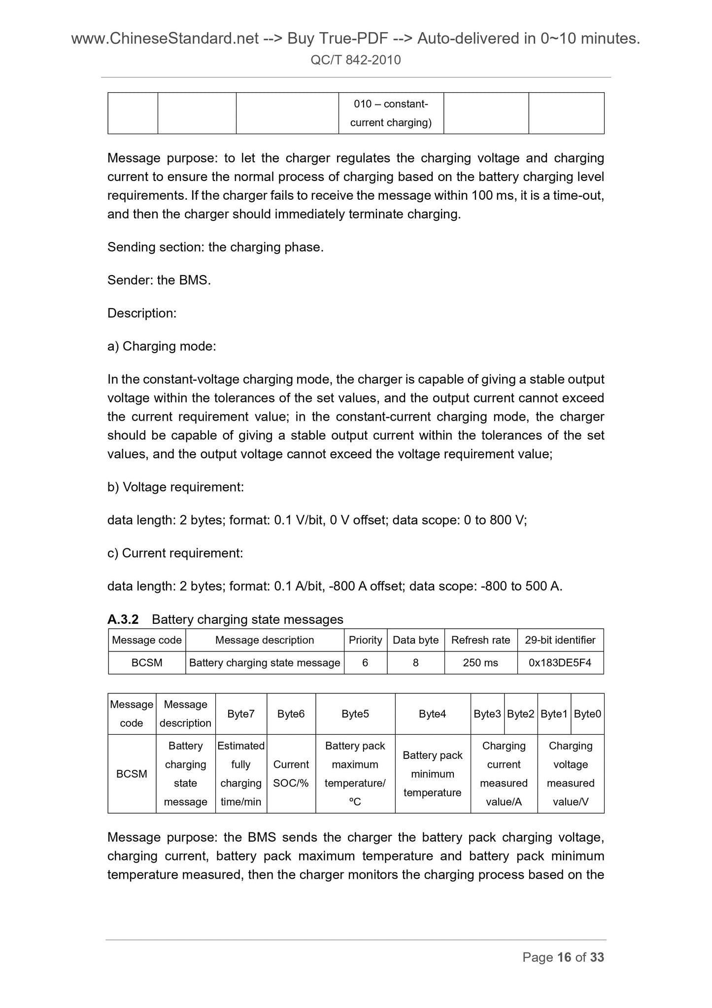
6.4 Charging phase
After the configuration phase, the BMS and charger enter the charging phase. During
the whole charging phase, the BMS controls the whole charging process by sending
in real time the battery charging level requirements to the charger. The charger
regulates the charging voltage and charging current to ensure the charging process
is normal based on the battery charging level requirements; in addition, the BMS and
charger also send each other their own charging states, and when the BMS sends a
message for the first time during the charging phase, it gives priority to the message
of the battery charging state.
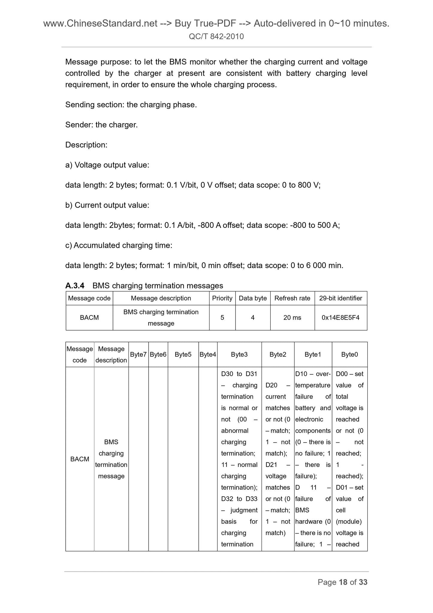
The BMS judges whether to terminate charging, in accordance with whether the
charging process is normal or not, whether the battery state meets the charging
termination conditions set by the BMS or not and whether the BMS receives the
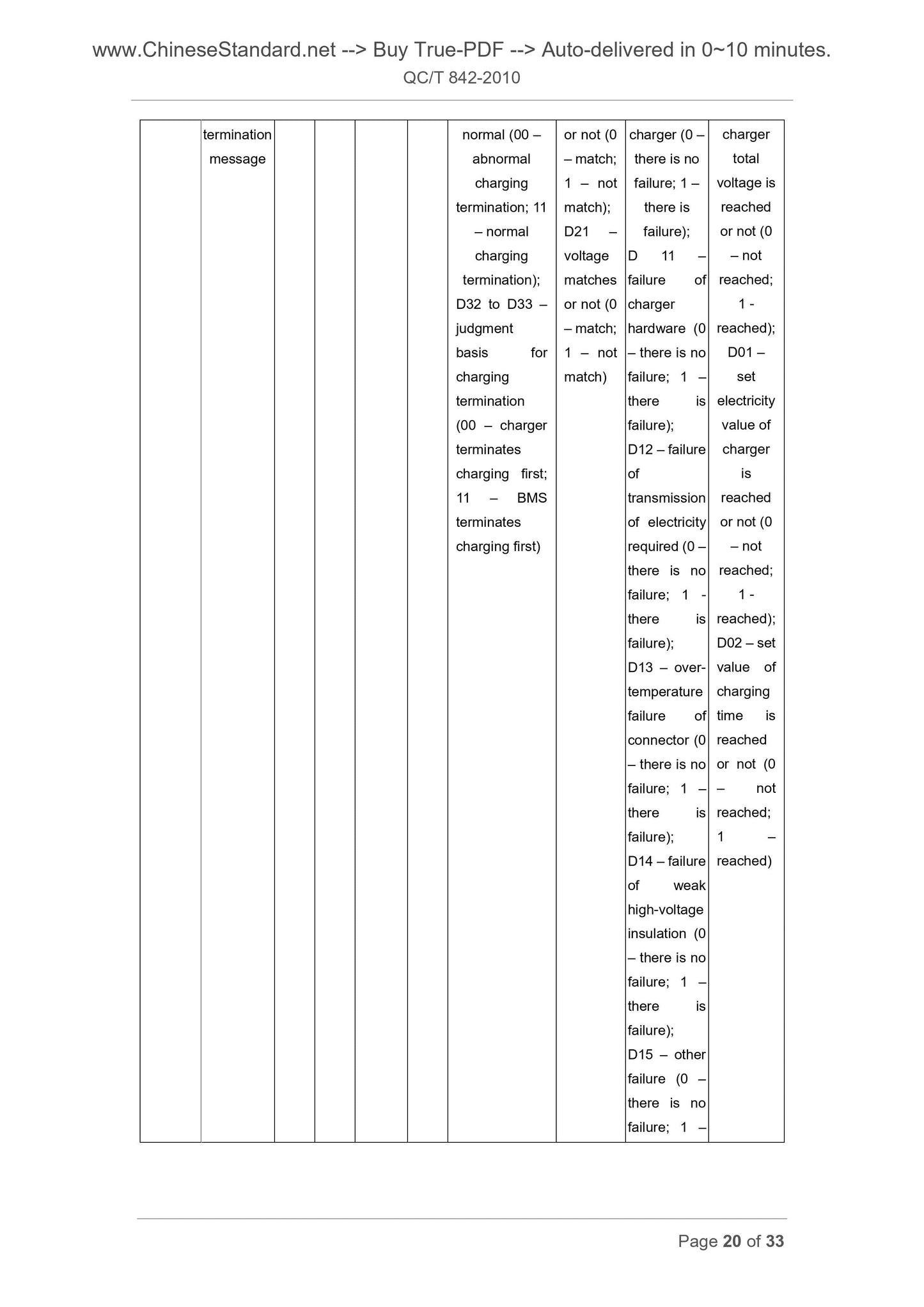
charging termination message from the charger; and the charger judges whether to
terminate charging, in accordance with whether the charging process is normal or
not, whether the charging parameters set by human are met or not and whether the
charging termination message from the BMS is received or not.
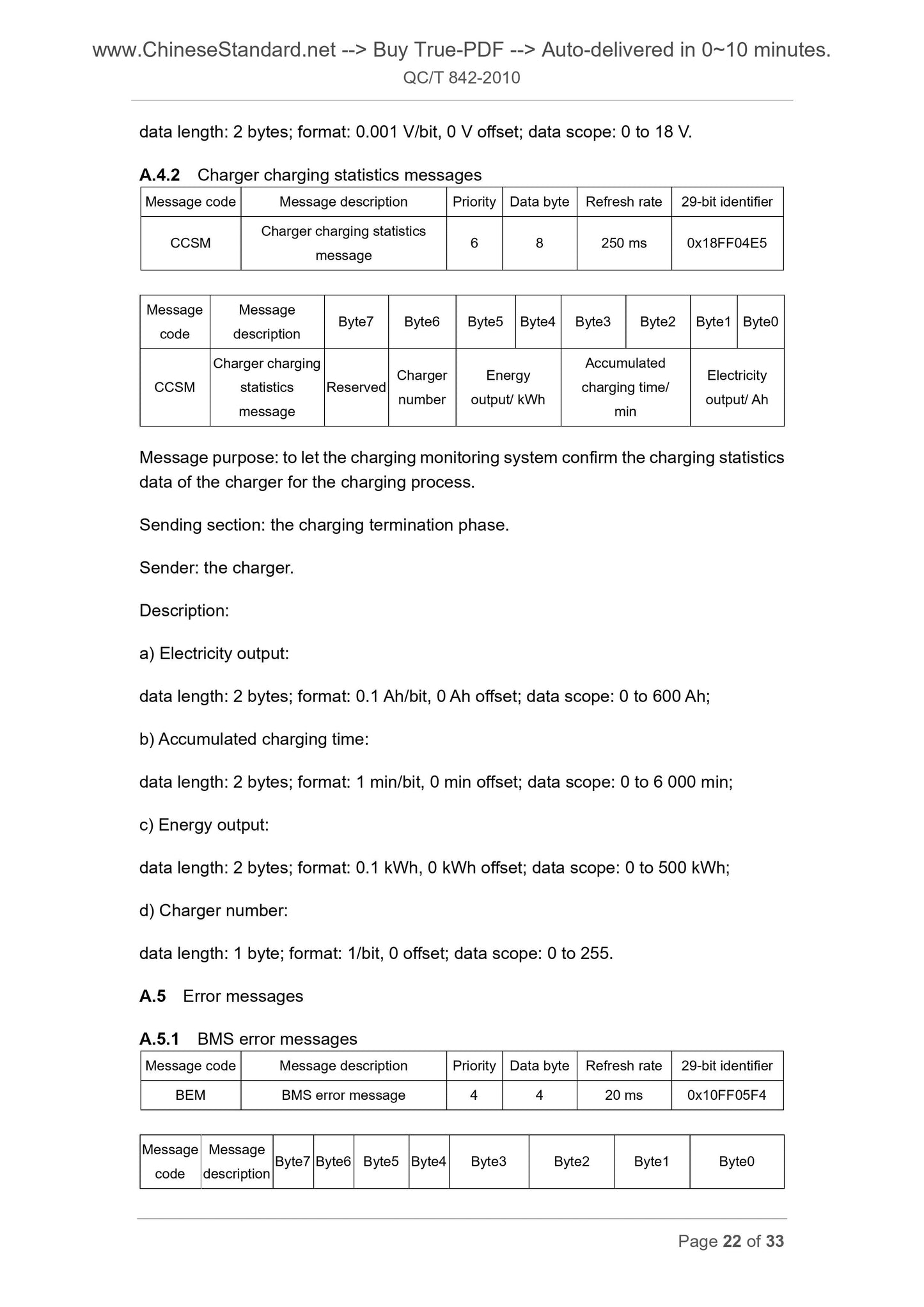
6.5 Charging termination phase
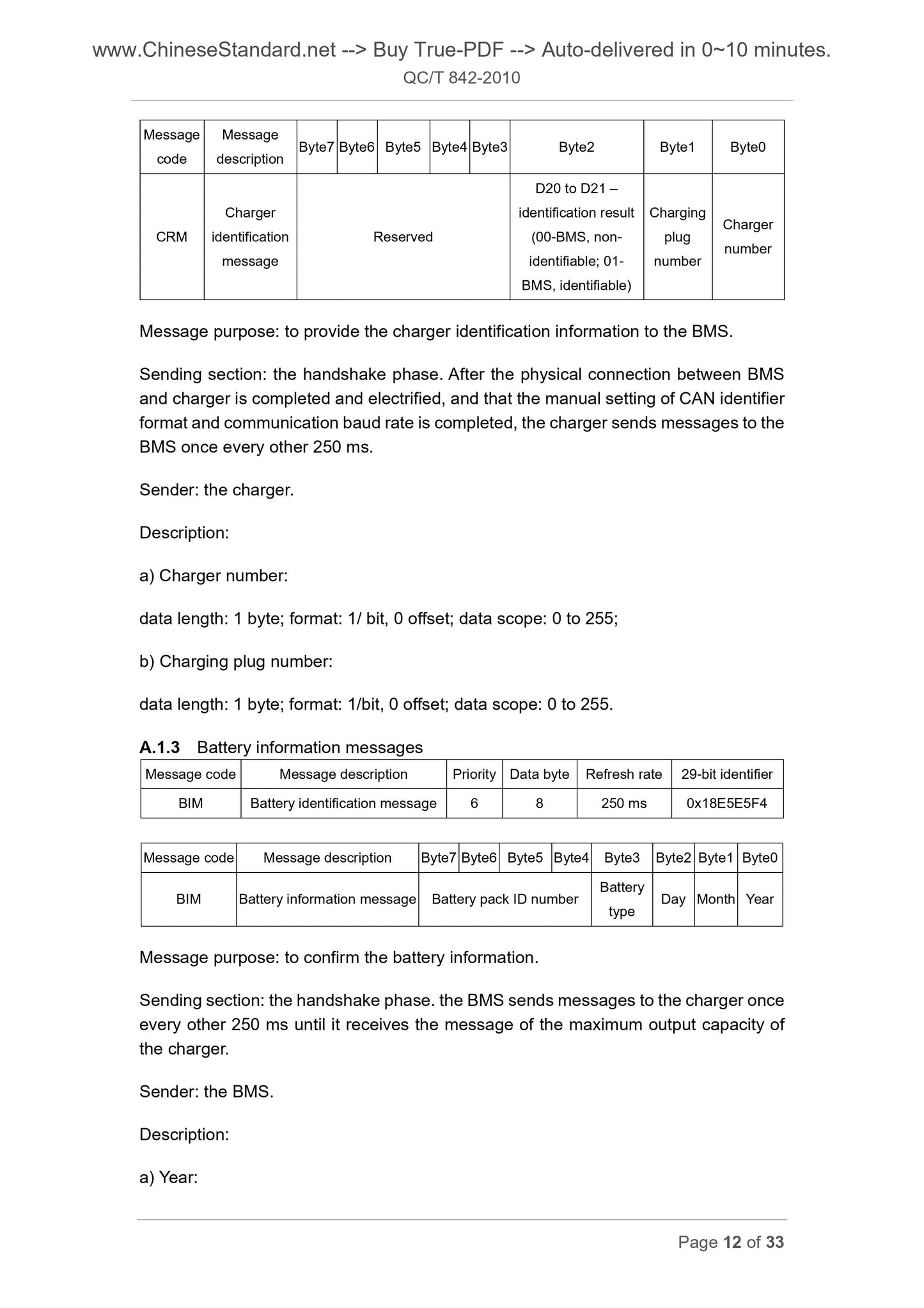
Message
code
Message
description Byte7 Byte6 Byte5 Byte4 Byte3 Byte2 Byte1 Byte0
CRM
Charger
identification
message
Reserved...
Get QUOTATION in 1-minute: Click QC/T 842-2010
Historical versions: QC/T 842-2010
Preview True-PDF (Reload/Scroll if blank)
QC/T 842-2010: Communication protocols between battery management system and off-board charger for electric vehicles
QC/T 842-2010
QC
AUTOMOTIVE INDUSTRY STANDARD
OF THE PEOPLE’S REPUBLIC OF CHINA
ICS 43.080
T 47
Communication Protocols between Battery
Management System and Off-board Charger for
Electric Vehicles
ISSUED ON. NOVEMBER 22, 2010
IMPLEMENTED ON. MARCH 1, 2011
Issued by. Ministry of Industry and Information Technology of the
People's Republic of China
Table of Contents
Foreword ... 3
1 Scope ... 4
2 Normative References ... 4
3 Terms and Definitions ... 5
4 Physical Layer Interface ... 6
5 Data Link Layer ... 6
6 Charging Process ... 8
Annex A (Normative) Format and Content of Application Layer Messages
... 11
Annex B (Informative) Charging Flow Charts ... 25
Foreword
The data frame format of this Standard is specified in CAN Bus Technical
Specifications 2.0 issued in September, 1991.
Annex A of this Standard is normative; Annex B is informative.
This Standard was proposed by and shall be under the jurisdiction of the National
Technical Committee of Auto Standardization.
The drafting organizations of this Standard. Tianjin Qingyuan Electric Vehicle Co., Ltd.,
China Automotive Technology and Research Center, Shenzhen BYD Co., Ltd., Chery
Automobile Co., Ltd., Beijing Institute of Technology, Beijing Jiaotong University,
Institute of Electrical Engineering Chinese Academy of Science and China Electronics
Technology Group Corporation No. 10 Research Institute.
The main drafters of this Standard. Zhao Chuning, Zhou Nenghui, Meng Xiangfeng,
Zhang Guangxiu, Wang Zhenpo, Jiang Jiuchun, Zhang Jianhua, Xiao Chengwei, Wang
Lifang, Li Lei, Fang Yunzhou and Wang Fang.
Communication Protocols between Battery
Management System and off-board Charger for
Electric Vehicles
1 Scope
This Standard specifies communication protocols between battery management
system (hereinafter referred to as BMS) and off-board charger (hereinafter referred to
as charger) for electric vehicles.
This Standard applies to off-board charging for electric vehicles.
CAN identifier of this Standard is 29 bits, and communication baud rate is 250 kbps,
but this Standard is not limited to 29-bit identifier and 250 kbps communication baud
rate. If other formats are used, their CAN identifier shall be made by reference to this
Standard.
Data transmission of this Standard is by the format of low bits transmitted first.
Negative current value represents charging; positive current value represents
discharging.
2 Normative References
The provisions in the following documents become part of this Part through reference
in this Standard. For dated documents, the subsequent amendments (excluding
corrigenda) or revisions do not apply to this Standard. However, all parties who enter
into agreement based on this Standard are encouraged to study whether the latest
versions of these documents are applicable. For undated documents, the latest
versions apply to this Standard.
ISO 11898-1.2006, Road Vehicles – Controller Area Network (CAN) – Part 1. Data
Link Layer and Physical Signalling
SAE J1939-11.2006, Recommended Practice for a Serial Control and
Communications Vehicle Network – Part 11. Physical Layer, 250K bits/s, Twisted
Shielded Pair
message
One or more CAN data frames with the same parameter group number
4 Physical Layer Interface
4.1 The Physical layer realizes the electric connection in the network between BMS
and charger
4.2 A CAN interface independent to the power assembly control system is preferred
for the communications between BMS and charger.
4.3 The Physical layer adopting this Standard shall meet the specifications of the
international standards ISO 11898-1 and SAE J1939-11.
5 Data Link Layer
5.1 General
Data link layer provides reliable data transmission between physical connections.
5.2 Frame format
As shown in Figure 1, the CAN extended data frame is divided into different bit fields,
where the arbitration field which has a 29-bit identifier, including an11-bit basic identifier
and an 18-bit identifier extension. The CAN data frame format of this Standard is
referred to SAE J1939-21; and the 29-bit identifier of the arbitration field is further
defined.
5.3 Protocol data unit
The CAN data frame includes a single protocol data unit (PDU), as shown in Figure 2.
The protocol data unit consists of seven parts, namely priority (P), reserved bits (R),
data page (DP), PDU format (PF), PDU specific (PS), source address (SA) and data
field.
The description of all parts in the protocol data unit is as follows.
5.3.1 Priority (P)
or charger fails to receive each other’s message within the specified period of time, it
is determined that it is a time-out, and the time-out time is always 5s, unless otherwise
specified; and in the event of a time-out, the BMS or charger sends the error message
and enters the error handling state. See Annex A for the formats and contents of
messages; and see Annex B for the overview flow charts and flow charts of all phases
of the charging process.
6.2 Handshake phase
After the physical connection between BMS and charger is completed and electrified,
and that the manual setting of CAN identifier format and communication baud rate is
completed, the BMS and charger enter the handshake phase. During the handshake
phase, the BMS first test whether the low-voltage auxiliary power supply is normal; if
it is not normal, the BMS sends error message to the charger, and the charge should
turn off the output of low-voltage power supply; if the low-voltage power supply is
normal, both sides shall do handshake during the phase, and determine the battery
information (e.g. battery type and manufacturing date of battery pack) and the
relevant information of the charger (e.g. charger number and charging plug number).
6.3 Configuration phase
After the handshake phase, the BMS and charger enter the configuration phase.
During the phase, the charger sends the message of its maximum output capacity to
the BMS; then the BMS judges whether charging can be done in accordance with the
maximum output capacity of the charger.
6.4 Charging phase
After the configuration phase, the BMS and charger enter the charging phase. During
the whole charging phase, the BMS controls the whole charging process by sending
in real time the battery charging level requirements to the charger. The charger
regulates the charging voltage and charging current to ensure the charging process
is normal based on the battery charging level requirements; in addition, the BMS and
charger also send each other their own charging states, and when the BMS sends a
message for the first time during the charging phase, it gives priority to the message
of the battery charging state.
The BMS judges whether to terminate charging, in accordance with whether the
charging process is normal or not, whether the battery state meets the charging
termination conditions set by the BMS or not and whether the BMS receives the
charging termination message from the charger; and the charger judges whether to
terminate charging, in accordance with whether the charging process is normal or
not, whether the charging parameters set by human are met or not and whether the
charging termination message from the BMS is received or not.
6.5 Charging termination phase
Message
code
Message
description Byte7 Byte6 Byte5 Byte4 Byte3 Byte2 Byte1 Byte0
CRM
Charger
identification
message
Reserved...
Share