1
/
의
12
PayPal, credit cards. Download editable-PDF and invoice in 1 second!
DL/T 5142-2012 English PDF (DLT5142-2012)
DL/T 5142-2012 English PDF (DLT5142-2012)
정가
$425.00 USD
정가
할인가
$425.00 USD
단가
/
단위
배송료는 결제 시 계산됩니다.
픽업 사용 가능 여부를 로드할 수 없습니다.
Delivery: 3 seconds. Download true-PDF + Invoice.
Get QUOTATION in 1-minute: Click DL/T 5142-2012
Historical versions: DL/T 5142-2012
Preview True-PDF (Reload/Scroll if blank)
DL/T 5142-2012: Technical code for the design of ash handling system of fossil-fired power plant
DL/T 5142-2012
DL
ELECTRICAL POWER INDUSTRY STANDARD
OF THE PEOPLE’S REPUBLIC OF CHINA
ICS 27.100
P 60
File No.: J1461-2012
Replacing DL/T 5142-2002
Technical Code for the Design of Ash Handling System of
Fossil-fired Power Plant
ISSUED ON: AUGUST 23, 2012
IMPLEMENTED ON: DECEMBER 1, 2012
Issued by: National Energy Administration
Table of Contents
Foreword ... 4
1 General Provisions ... 9
2 Terms ... 11
3 Pneumatic Ash Handling System ... 12
3.1 Basic Requirement ... 12
3.2 Positive Pressure Pneumatic Conveying ... 12
3.3 Negative Pressure Pneumatic Conveying ... 15
3.4 Pneumatic Ash Conveying Pipeline ... 17
3.5 Air Slide ... 18
3.6 Dry Ash Classifying System ... 19
4 Hydraulic Ash Handling System ... 20
4.1 Basic Requirement ... 20
4.2 Water Supply for Ash Handling System ... 21
4.3 Hydraulic Jet Pump ... 22
4.4 Ash Trench ... 23
4.5 Ash Slurrying Facilities ... 25
4.6 Centrifugal Ash Slurry Pump ... 26
4.7 Plunger Ash Slurry Pump ... 27
4.8 Dewatering Bin and Settling Facilities ... 28
4.9 Slag Settling Pond ... 28
4.10 Hydraulic Ash Conveying Pipeline ... 29
5 Mechanical Ash Handling System ... 32
5.1 Basic Requirement ... 32
5.2 Air-cooled Type Slag Conveyor... 32
5.3 Submerged Scraper Conveyor ... 33
5.4 Buried-plate Conveyor ... 34
5.5 Vertical Bucket Elevator ... 36
5.6 Bucket Conveyor ... 37
6 Mill Reject Conveying System ... 38
6.1 Basic Requirement ... 38
6.2 Simple Mechanical Conveying ... 38
6.3 Hydraulic Jet Pump Conveying ... 38
6.4 Mechanical Conveying ... 39
7 Compressed Air Supply System ... 40
7.1 Basic Requirement ... 40
7.2 Air Compressor and Treatment Facilities of Compressed Air ... 40
7.3 Rotary Blower and Vacuum Pump ... 42
8 Material Storage and Unloading System ... 43
8.1 Basic Requirement ... 43
8.2 Ash Silo and Ash Hopper ... 44
8.3 Slag Bin and Mill Reject Bin ... 45
8.4 Unloading System and Equipment Selection ... 46
9 Off-site Conveying System ... 47
9.1 Basic Requirement ... 47
9.2 Automobile Transportation ... 47
9.3 Belt Conveyor ... 49
9.4 Ship Transportation ... 53
10 Ash Handling System for CFB Boiler ... 57
10.1 Basic Requirement ... 57
10.2 Slag Handling System ... 58
10.3 Limestone Powder Handling System ... 58
11 Ash Handling System for Municipal Solid Waste Incineration Power Plant ... 60
11.1 Basic Requirement ... 60
11.2 Slag Handling System ... 60
11.3 Ash Handling System ... 61
12 Ash Handling System for Straw Power Plant ... 63
12.1 Basic Requirement ... 63
12.2 Mechanical Ash Handling System ... 63
12.3 Pneumatic Ash Handling System ... 63
12.4 Ash Storage ... 64
13 Slime Pipelines Conveying System ... 65
13.1 Basic Requirement ... 65
13.2 Slime Pipelines Conveying ... 65
13.3 Equipment Selection ... 65
13.4 Slime Pump House ... 65
14 Design Requirements for Relevant Specialties ... 67
14.1 Boiler and Auxiliaries ... 67
14.2 I and C and Electrical ... 67
14.3 Civil Engineering and Hydro-structure ... 69
14.4 Hydraulic and Chemical ... 69
14.5 Heating and Ventilating ... 70
14.6 General Plan Transportation ... 70
Appendix A Calculation of Ash Amount ... 71
Appendix B Calculation of Mill Rejects Amount ... 73
2 Terms
2.0.1 Particle density
The ratio of the material mass to its true volume.
2.0.2 Loose-poured bulk density
The mass per unit volume of particle materials under natural stacking state.
2.0.3 Slurry weight density
The percentage of solid weight, flowing in unit time, in the slurry weight.
2.0.4 Material gas ratio
The ratio of the material mass, being conveyed in unit time in the pneumatic conveying
pipeline, to the gas mass
2.0.5 Percentage of mill rejects
The percentage of mill reject amount, being discharged by the medium speed coal mill in
unit time, in the coal amount entering into coal mill.
3 Pneumatic Ash Handling System
3.1 Basic Requirement
3.1.1 The on-site ash conveying system should adopt positive pressure pneumatic
conveying system. Where the material characteristics and conveying conditions are suitable,
positive pressure dense phase pneumatic conveying system should be adopted.
3.1.2 According to different conveying distances, pneumatic ash conveying system may
adopt air slide, negative pressure and other conveying modes and should meet the following
requirements:
1 Where the conveying distance is shorter than 60m, air slide conveying mode may be
adopted.
2 Where the length of conveying pipeline does not exceed 150m, negative pressure
pneumatic conveying system may be adopted.
3 In combination with specific engineering conditions, system combined by various
pneumatic conveying modes may be adopted.
3.1.3 Where the slag warehouse is relatively far and it is difficult to arrange mechanical
conveying equipment, pneumatic slag conveying system may be adopted.
3.1.4 The flow velocity of pneumatic ash handling pipeline shall be determined reasonably
according to such factors as ash particle diameter, density, conveying pipe diameter and ash
handling and conveying system.
3.1.5 The pneumatic conveying system design shall consider the effects from local air
pressure, air temperature, humidity and other natural conditions.
3.1.6 Where the boiler adopts electric precipitator, the ash conveying system output of the
following stage electric fields shall not be less than the ash amount of the earlier stage electric
field under normal working conditions when the preceding stage electric field loses of power.
3.1.7 Where the boiler slag handling adopts the combined system of air-cooled type slag
conveyor and pneumatic slag conveying, high-temperature resistant slag crusher shall be
arranged at the outlet of air-cooled type slag conveyor, and the particle size of slag discharged
by the slag crusher shall meet the conveying requirements. Buffer slag hopper should be
arranged between the slag crusher outlet and the pneumatic conveying equipment.
3.2 Positive Pressure Pneumatic Conveying
3.2.1 The design output of positive pressure pneumatic ash conveying system should not be
less than 150% of the ash discharge amount of boiler when it fires the design coal at the
working condition of maximum continuous evaporation and should not be less than 120% of
the ash discharge amount of boiler when it fires the check coal.
3.2.2 Two sets of positive pressure pneumatic slag conveying systems should be set for each
boiler that one for operation and the other for standby. The design output of each set of system
should not be less than 150% slag discharge amount of design coal and should not be less
than 120% slag discharge amount of check coal.
3.2.3 The bin type pneumatic conveying pump (hereinafter referred to as bin pump) under
the precipitator ash hopper should be arranged in groups. As for the bin pump under the first
electric field of electric precipitator and the ash hopper of baghose precipitator, the quantity of
bin pumps being operated simultaneously in each group should not exceed 6.
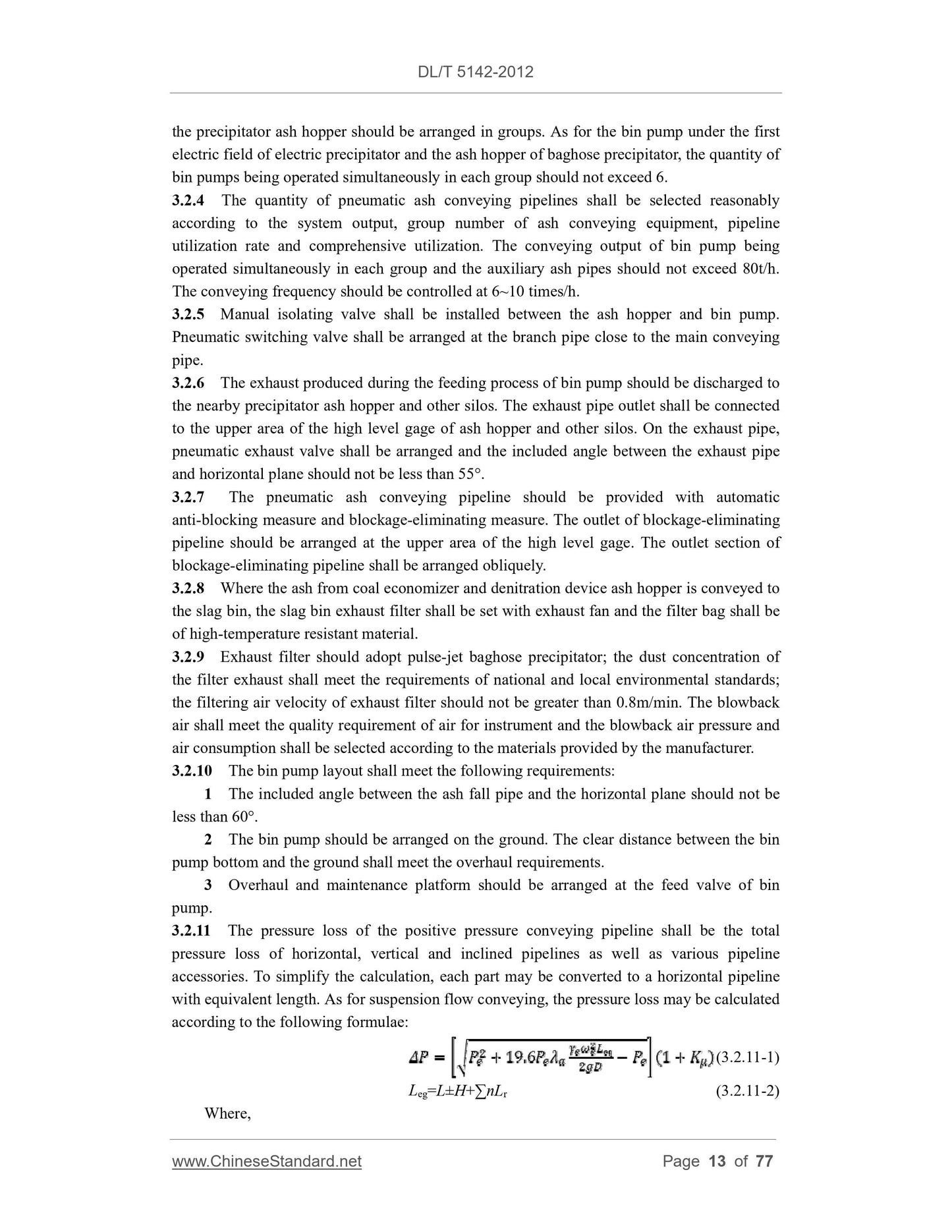
3.2.4 The quantity of pneumatic ash conveying pipelines shall be selected reasonably
according to the system output, group number of ash conveying equipment, pipeline
utilization rate and comprehensive utilization. The conveying output of bin pump being
operated simultaneously in each group and the auxiliary ash pipes should not exceed 80t/h.
The conveying frequency should be controlled at 6~10 times/...
Get QUOTATION in 1-minute: Click DL/T 5142-2012
Historical versions: DL/T 5142-2012
Preview True-PDF (Reload/Scroll if blank)
DL/T 5142-2012: Technical code for the design of ash handling system of fossil-fired power plant
DL/T 5142-2012
DL
ELECTRICAL POWER INDUSTRY STANDARD
OF THE PEOPLE’S REPUBLIC OF CHINA
ICS 27.100
P 60
File No.: J1461-2012
Replacing DL/T 5142-2002
Technical Code for the Design of Ash Handling System of
Fossil-fired Power Plant
ISSUED ON: AUGUST 23, 2012
IMPLEMENTED ON: DECEMBER 1, 2012
Issued by: National Energy Administration
Table of Contents
Foreword ... 4
1 General Provisions ... 9
2 Terms ... 11
3 Pneumatic Ash Handling System ... 12
3.1 Basic Requirement ... 12
3.2 Positive Pressure Pneumatic Conveying ... 12
3.3 Negative Pressure Pneumatic Conveying ... 15
3.4 Pneumatic Ash Conveying Pipeline ... 17
3.5 Air Slide ... 18
3.6 Dry Ash Classifying System ... 19
4 Hydraulic Ash Handling System ... 20
4.1 Basic Requirement ... 20
4.2 Water Supply for Ash Handling System ... 21
4.3 Hydraulic Jet Pump ... 22
4.4 Ash Trench ... 23
4.5 Ash Slurrying Facilities ... 25
4.6 Centrifugal Ash Slurry Pump ... 26
4.7 Plunger Ash Slurry Pump ... 27
4.8 Dewatering Bin and Settling Facilities ... 28
4.9 Slag Settling Pond ... 28
4.10 Hydraulic Ash Conveying Pipeline ... 29
5 Mechanical Ash Handling System ... 32
5.1 Basic Requirement ... 32
5.2 Air-cooled Type Slag Conveyor... 32
5.3 Submerged Scraper Conveyor ... 33
5.4 Buried-plate Conveyor ... 34
5.5 Vertical Bucket Elevator ... 36
5.6 Bucket Conveyor ... 37
6 Mill Reject Conveying System ... 38
6.1 Basic Requirement ... 38
6.2 Simple Mechanical Conveying ... 38
6.3 Hydraulic Jet Pump Conveying ... 38
6.4 Mechanical Conveying ... 39
7 Compressed Air Supply System ... 40
7.1 Basic Requirement ... 40
7.2 Air Compressor and Treatment Facilities of Compressed Air ... 40
7.3 Rotary Blower and Vacuum Pump ... 42
8 Material Storage and Unloading System ... 43
8.1 Basic Requirement ... 43
8.2 Ash Silo and Ash Hopper ... 44
8.3 Slag Bin and Mill Reject Bin ... 45
8.4 Unloading System and Equipment Selection ... 46
9 Off-site Conveying System ... 47
9.1 Basic Requirement ... 47
9.2 Automobile Transportation ... 47
9.3 Belt Conveyor ... 49
9.4 Ship Transportation ... 53
10 Ash Handling System for CFB Boiler ... 57
10.1 Basic Requirement ... 57
10.2 Slag Handling System ... 58
10.3 Limestone Powder Handling System ... 58
11 Ash Handling System for Municipal Solid Waste Incineration Power Plant ... 60
11.1 Basic Requirement ... 60
11.2 Slag Handling System ... 60
11.3 Ash Handling System ... 61
12 Ash Handling System for Straw Power Plant ... 63
12.1 Basic Requirement ... 63
12.2 Mechanical Ash Handling System ... 63
12.3 Pneumatic Ash Handling System ... 63
12.4 Ash Storage ... 64
13 Slime Pipelines Conveying System ... 65
13.1 Basic Requirement ... 65
13.2 Slime Pipelines Conveying ... 65
13.3 Equipment Selection ... 65
13.4 Slime Pump House ... 65
14 Design Requirements for Relevant Specialties ... 67
14.1 Boiler and Auxiliaries ... 67
14.2 I and C and Electrical ... 67
14.3 Civil Engineering and Hydro-structure ... 69
14.4 Hydraulic and Chemical ... 69
14.5 Heating and Ventilating ... 70
14.6 General Plan Transportation ... 70
Appendix A Calculation of Ash Amount ... 71
Appendix B Calculation of Mill Rejects Amount ... 73
2 Terms
2.0.1 Particle density
The ratio of the material mass to its true volume.
2.0.2 Loose-poured bulk density
The mass per unit volume of particle materials under natural stacking state.
2.0.3 Slurry weight density
The percentage of solid weight, flowing in unit time, in the slurry weight.
2.0.4 Material gas ratio
The ratio of the material mass, being conveyed in unit time in the pneumatic conveying
pipeline, to the gas mass
2.0.5 Percentage of mill rejects
The percentage of mill reject amount, being discharged by the medium speed coal mill in
unit time, in the coal amount entering into coal mill.
3 Pneumatic Ash Handling System
3.1 Basic Requirement
3.1.1 The on-site ash conveying system should adopt positive pressure pneumatic
conveying system. Where the material characteristics and conveying conditions are suitable,
positive pressure dense phase pneumatic conveying system should be adopted.
3.1.2 According to different conveying distances, pneumatic ash conveying system may
adopt air slide, negative pressure and other conveying modes and should meet the following
requirements:
1 Where the conveying distance is shorter than 60m, air slide conveying mode may be
adopted.
2 Where the length of conveying pipeline does not exceed 150m, negative pressure
pneumatic conveying system may be adopted.
3 In combination with specific engineering conditions, system combined by various
pneumatic conveying modes may be adopted.
3.1.3 Where the slag warehouse is relatively far and it is difficult to arrange mechanical
conveying equipment, pneumatic slag conveying system may be adopted.
3.1.4 The flow velocity of pneumatic ash handling pipeline shall be determined reasonably
according to such factors as ash particle diameter, density, conveying pipe diameter and ash
handling and conveying system.
3.1.5 The pneumatic conveying system design shall consider the effects from local air
pressure, air temperature, humidity and other natural conditions.
3.1.6 Where the boiler adopts electric precipitator, the ash conveying system output of the
following stage electric fields shall not be less than the ash amount of the earlier stage electric
field under normal working conditions when the preceding stage electric field loses of power.
3.1.7 Where the boiler slag handling adopts the combined system of air-cooled type slag
conveyor and pneumatic slag conveying, high-temperature resistant slag crusher shall be
arranged at the outlet of air-cooled type slag conveyor, and the particle size of slag discharged
by the slag crusher shall meet the conveying requirements. Buffer slag hopper should be
arranged between the slag crusher outlet and the pneumatic conveying equipment.
3.2 Positive Pressure Pneumatic Conveying
3.2.1 The design output of positive pressure pneumatic ash conveying system should not be
less than 150% of the ash discharge amount of boiler when it fires the design coal at the
working condition of maximum continuous evaporation and should not be less than 120% of
the ash discharge amount of boiler when it fires the check coal.
3.2.2 Two sets of positive pressure pneumatic slag conveying systems should be set for each
boiler that one for operation and the other for standby. The design output of each set of system
should not be less than 150% slag discharge amount of design coal and should not be less
than 120% slag discharge amount of check coal.
3.2.3 The bin type pneumatic conveying pump (hereinafter referred to as bin pump) under
the precipitator ash hopper should be arranged in groups. As for the bin pump under the first
electric field of electric precipitator and the ash hopper of baghose precipitator, the quantity of
bin pumps being operated simultaneously in each group should not exceed 6.
3.2.4 The quantity of pneumatic ash conveying pipelines shall be selected reasonably
according to the system output, group number of ash conveying equipment, pipeline
utilization rate and comprehensive utilization. The conveying output of bin pump being
operated simultaneously in each group and the auxiliary ash pipes should not exceed 80t/h.
The conveying frequency should be controlled at 6~10 times/...
Share