1
/
의
7
PayPal, credit cards. Download editable-PDF & invoice in 1 second!
GB/T 9766.3-2016 English PDF (GBT9766.3-2016)
GB/T 9766.3-2016 English PDF (GBT9766.3-2016)
정가
$85.00 USD
정가
할인가
$85.00 USD
단가
/
단위
배송료는 결제 시 계산됩니다.
픽업 사용 가능 여부를 로드할 수 없습니다.
Delivery: 3 seconds. Download true-PDF + Invoice.
Get QUOTATION in 1-minute: Click GB/T 9766.3-2016
Historical versions: GB/T 9766.3-2016
Preview True-PDF (Reload/Scroll if blank)
GB/T 9766.3-2016: Test method for tyre valves -- Part 3: Test methods for snap-in valves
GB/T 9766.3-2016
GB
NATIONAL STANDARD OF THE
PEOPLE’S REPUBLIC OF CHINA
ICS 83.160.01
G 41
Replacing GB/T 9766.3-2008
Test Method for Tyre Valves –
Part 3. Test Methods for Snap-in Valves
(ISO 14960.2004, Tubeless Tyres –
Valves and Components – Test Methods, MOD)
ISSUED ON. FEBRUARY 24, 2016
IMPLEMENTED ON. JANUARY 1, 2017
Issued by. General Administration of Quality Supervision, Inspection and
Quarantine;
Standardization Administration of PRC.
Table of Contents
Foreword ... 3
1 Scope ... 5
2 Normative References ... 5
3 Terms and Definitions ... 5
4 Test Equipment, Apparatus ... 5
5 Test Device ... 6
6 Test Procedures ... 7
Appendix A (Informative) Structural Changes between this Part and ISO
14960.2004 ... 16
Appendix B (Informative) Technical Differences and Causes between this
Part and ISO 14960.2004 ... 19
Foreword
GB/T 9766 Test Method for Tyre Valves can be divided into the following 7 parts.
--- Part 1. Test Methods for Clamp-In Valves;
--- Part 2. Test Methods for Rubber Base Seat Valves;
--- Part 3. Test Methods for Snap-In Valves;
--- Part 4. Test Methods for Clamp-In Tubeless Valves;
--- Part 5. Test Methods for Tyre Valves for Large Core Chamber;
--- Part 6. Test Methods for Core;
--- Part 7. Test Methods for Components.
This Part belongs to Part 3 of GB/T 9766.
This Part was drafted as per the rules specified in GB/T 1.1-2009.
This Part replaced GB/T 9766.3-2008 Test Method for Tyre Valves – Part 3. Snap-In
Valves – Test Methods; compared with GB/T 9766.3-2008, this Part has the major
technical changes as follows.
--- Increase, in the Foreword, “Part 7. Test Methods for Components” (see
Foreword);
--- Modify the scope (see Chapter 1 of this Edition; Chapter 1 of 2008 Edition);
--- Delete terms “test valves” and “aging valves” (see 3.1, 3.2 of 2008 Edition);
--- Modify pressure gauge accuracy grade (see 4.4 of this Edition; 4.4 of 2008
Edition);
--- Modify the description of test equipment in 5.2 (see 5.2 of this Edition; 5.2 of
2008 Edition);
--- Increase the test hole specification in nominal size of Φ8.8 (see Table 1);
--- Increase the provision on the reading time of rubber hardness test (see 6.1);
--- Modify the core mounting torque (see 6.3.1 of this Edition; 6.3.1 of 2008 Edition);
--- Delete the seal test of seal cap (see 6.4 of 2008 Edition);
--- Increase the provisions on bending degree of seal test on CQ07C, CQ08C valves
Test Method for Tyre Valves –
Part 3. Test Methods for Snap-in Valves
1 Scope
This Part of GB/T 9766 specifies the terms and definitions, test equipment, apparatus,
test device, and test procedures of snap-in valve (hereinafter referred to as “valve”).
This Part is applicable to the tubeless tyre used valve test for the hand cart, motorcycle,
car, light truck, and truck.
2 Normative References
The following documents are essential to the application of this document. For the
dated documents, only the versions with the dates indicated are applicable to this
document; for the undated documents, only the latest version (including all the
amendments) are applicable to this document.
GB 1796.3 Tyre Valves – Part 3. Snap-In Valves (GB 1796.3-2008, ISO 9413.
1998, ISO 14960.2004, NEQ)
GB 1796.6 Tyre Valves – Part 6. Cores (GB 1796.6-2008, ISO 9413.1998, NEQ)
GB/T 12839 Terms and Definitions of Tyre Valves (GB/T 12839-2012, ISO 3877-
2.1997, NEQ)
3 Terms and Definitions
The terms and definitions stipulated in GB/T 12839 are applicable to this document.
4 Test Equipment, Apparatus
4.1 Tensile tester. load 0N~2000N, the relative change value of indicating value is
1%.
4.2 High temperature chamber. the temperature inside the chamber can reach 200°C
above, the temperature fluctuation is ±2°C.
1 – pressure regulating valve;
2 – pressure gauge.
Figure 5
6.4.2 Low temperature test
6.4.2.1 test procedures
6.4.2.1.1 Install the valve onto the test device as per the instructions in 5.2 and 5.3.
6.4.2.1.2 Place the installed valve at (-40±3) °C for at least 24h, so that ensure the
sealing area is within the test temperature.
6.4.2.1.3 At the constant pressure of (180±15)kPa, immerse the installed valve into
(-40±3) °C ethanol; the valve mouth shall be upward, the distance between valve rim
sealing part and the liquid surface shall be no greater than 100mm.
6.4.2.1.4 The valve immersed into the liquid shall be bent for 25°±3° against the valve
installing hole axis (CQ07C, CQ08C valves shall not be bent); rotate the valve around
the installing hole axis evenly for a turn within 15s~45s, and exert no torque to the
valve.
6.4.2.1.5 Repeat 6.4.2.1.3~6.4.2.1.4 with interval for at least 0.5h once, totally 5
times.
6.4.2.2 Qualification judgment
If the leakage rate is less than 0.2cm3/min, or before, in the middle, and after rotating
and bending the valve, there is no bubbles on the rim sealing place within 60s, then
the valve is judged as qualified.
NOTE. the attached gas during the installation period shall not be regarded as leakage.
6.4.3 High temperature test
6.4.3.1 Test procedures
6.4.3.1.1 Install the valve onto the test device as per the instructions in 5.2 and 5.3.
6.4.3.1.2 Place the installed valve into (100±3) °C heat-circulating air for 48h to
simulate the aging condition.
6.4.3.1.3 At the pressure of (600±15)kPa, immerse the installed valve into (66±3) °C
clean water; the valve mouth shall be upward, the distance between valve rim sealing
part and the liquid surface shall be no greater than 100mm.
6.4.3.1.4 The valve immersed into the liquid shall be bent for 25°±3° against the valve
installing hole axis (CQ07C, CQ08C valves shall bent 10°±3°); rotate the valve around
the installing hole axis evenly for a turn within 15s~45s, and exert no torque to the
valve.
6.4.3.1.5 Place the reloaded valve into the heat-circulating air again.
6.4.3.1.6 Repeat 6.4.3.1.3~6.4.3.1.5 with interval at least 0.5h once, totally 5 times;
the final bending and rotating shall be finished at the 72nd h in the test period.
6.4.3.2 Qualification judgment
If the leakage rate is less than 0.2cm3/min, or before, in the middle, and after rotating
and bending the valve, there is no bubbles on the rim sealing place within 60s, then
the valve is judged as qualified.
NOTE. the attached gas during the installation period shall not be regarded as leakage.
6.5 Assembly test
6.5.1 Pull-in force
Take water as the lubricant; install the immersed valve onto the tension tester; pull the
valve at the speed of (150±15) mm/min; stop till the marking ring of the valve body is
totally passed through the test device plate hole stipulated in 5.2; during this period,
the maximum tension is regarded as the pull-in force (see Figure 6).
6.5.2 Qualification judgment
The pull-in force shall conform to the provisions of GB 1796.3; if valve is damaged
during the test, it shall be judged as disqualified.
Appendix B
(Informative)
Technical Differences and Causes
between this Part and ISO 14960.2004
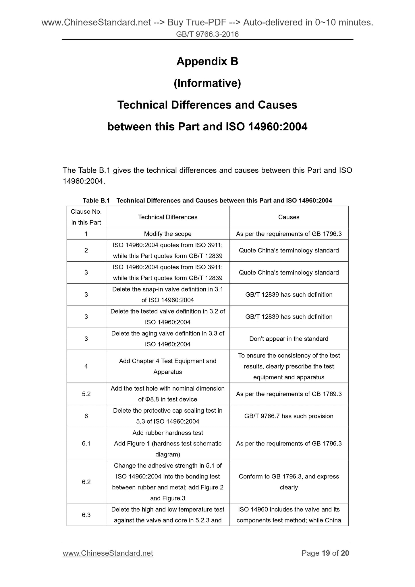
The Table B.1 gives the technical differences and causes between this Part and ISO
14960.2004.
Table B.1 Technical Differences and Causes between this Part and ISO 14960.2004
Clause No.
in this Part Technical Differences Causes
1 Modify the scope As per the requirements of GB 1796.3
2 ISO 14960.2004 quotes from ISO 3911; while this Part quotes form GB/T 12839 Quote China’s terminology standard <...
Get QUOTATION in 1-minute: Click GB/T 9766.3-2016
Historical versions: GB/T 9766.3-2016
Preview True-PDF (Reload/Scroll if blank)
GB/T 9766.3-2016: Test method for tyre valves -- Part 3: Test methods for snap-in valves
GB/T 9766.3-2016
GB
NATIONAL STANDARD OF THE
PEOPLE’S REPUBLIC OF CHINA
ICS 83.160.01
G 41
Replacing GB/T 9766.3-2008
Test Method for Tyre Valves –
Part 3. Test Methods for Snap-in Valves
(ISO 14960.2004, Tubeless Tyres –
Valves and Components – Test Methods, MOD)
ISSUED ON. FEBRUARY 24, 2016
IMPLEMENTED ON. JANUARY 1, 2017
Issued by. General Administration of Quality Supervision, Inspection and
Quarantine;
Standardization Administration of PRC.
Table of Contents
Foreword ... 3
1 Scope ... 5
2 Normative References ... 5
3 Terms and Definitions ... 5
4 Test Equipment, Apparatus ... 5
5 Test Device ... 6
6 Test Procedures ... 7
Appendix A (Informative) Structural Changes between this Part and ISO
14960.2004 ... 16
Appendix B (Informative) Technical Differences and Causes between this
Part and ISO 14960.2004 ... 19
Foreword
GB/T 9766 Test Method for Tyre Valves can be divided into the following 7 parts.
--- Part 1. Test Methods for Clamp-In Valves;
--- Part 2. Test Methods for Rubber Base Seat Valves;
--- Part 3. Test Methods for Snap-In Valves;
--- Part 4. Test Methods for Clamp-In Tubeless Valves;
--- Part 5. Test Methods for Tyre Valves for Large Core Chamber;
--- Part 6. Test Methods for Core;
--- Part 7. Test Methods for Components.
This Part belongs to Part 3 of GB/T 9766.
This Part was drafted as per the rules specified in GB/T 1.1-2009.
This Part replaced GB/T 9766.3-2008 Test Method for Tyre Valves – Part 3. Snap-In
Valves – Test Methods; compared with GB/T 9766.3-2008, this Part has the major
technical changes as follows.
--- Increase, in the Foreword, “Part 7. Test Methods for Components” (see
Foreword);
--- Modify the scope (see Chapter 1 of this Edition; Chapter 1 of 2008 Edition);
--- Delete terms “test valves” and “aging valves” (see 3.1, 3.2 of 2008 Edition);
--- Modify pressure gauge accuracy grade (see 4.4 of this Edition; 4.4 of 2008
Edition);
--- Modify the description of test equipment in 5.2 (see 5.2 of this Edition; 5.2 of
2008 Edition);
--- Increase the test hole specification in nominal size of Φ8.8 (see Table 1);
--- Increase the provision on the reading time of rubber hardness test (see 6.1);
--- Modify the core mounting torque (see 6.3.1 of this Edition; 6.3.1 of 2008 Edition);
--- Delete the seal test of seal cap (see 6.4 of 2008 Edition);
--- Increase the provisions on bending degree of seal test on CQ07C, CQ08C valves
Test Method for Tyre Valves –
Part 3. Test Methods for Snap-in Valves
1 Scope
This Part of GB/T 9766 specifies the terms and definitions, test equipment, apparatus,
test device, and test procedures of snap-in valve (hereinafter referred to as “valve”).
This Part is applicable to the tubeless tyre used valve test for the hand cart, motorcycle,
car, light truck, and truck.
2 Normative References
The following documents are essential to the application of this document. For the
dated documents, only the versions with the dates indicated are applicable to this
document; for the undated documents, only the latest version (including all the
amendments) are applicable to this document.
GB 1796.3 Tyre Valves – Part 3. Snap-In Valves (GB 1796.3-2008, ISO 9413.
1998, ISO 14960.2004, NEQ)
GB 1796.6 Tyre Valves – Part 6. Cores (GB 1796.6-2008, ISO 9413.1998, NEQ)
GB/T 12839 Terms and Definitions of Tyre Valves (GB/T 12839-2012, ISO 3877-
2.1997, NEQ)
3 Terms and Definitions
The terms and definitions stipulated in GB/T 12839 are applicable to this document.
4 Test Equipment, Apparatus
4.1 Tensile tester. load 0N~2000N, the relative change value of indicating value is
1%.
4.2 High temperature chamber. the temperature inside the chamber can reach 200°C
above, the temperature fluctuation is ±2°C.
1 – pressure regulating valve;
2 – pressure gauge.
Figure 5
6.4.2 Low temperature test
6.4.2.1 test procedures
6.4.2.1.1 Install the valve onto the test device as per the instructions in 5.2 and 5.3.
6.4.2.1.2 Place the installed valve at (-40±3) °C for at least 24h, so that ensure the
sealing area is within the test temperature.
6.4.2.1.3 At the constant pressure of (180±15)kPa, immerse the installed valve into
(-40±3) °C ethanol; the valve mouth shall be upward, the distance between valve rim
sealing part and the liquid surface shall be no greater than 100mm.
6.4.2.1.4 The valve immersed into the liquid shall be bent for 25°±3° against the valve
installing hole axis (CQ07C, CQ08C valves shall not be bent); rotate the valve around
the installing hole axis evenly for a turn within 15s~45s, and exert no torque to the
valve.
6.4.2.1.5 Repeat 6.4.2.1.3~6.4.2.1.4 with interval for at least 0.5h once, totally 5
times.
6.4.2.2 Qualification judgment
If the leakage rate is less than 0.2cm3/min, or before, in the middle, and after rotating
and bending the valve, there is no bubbles on the rim sealing place within 60s, then
the valve is judged as qualified.
NOTE. the attached gas during the installation period shall not be regarded as leakage.
6.4.3 High temperature test
6.4.3.1 Test procedures
6.4.3.1.1 Install the valve onto the test device as per the instructions in 5.2 and 5.3.
6.4.3.1.2 Place the installed valve into (100±3) °C heat-circulating air for 48h to
simulate the aging condition.
6.4.3.1.3 At the pressure of (600±15)kPa, immerse the installed valve into (66±3) °C
clean water; the valve mouth shall be upward, the distance between valve rim sealing
part and the liquid surface shall be no greater than 100mm.
6.4.3.1.4 The valve immersed into the liquid shall be bent for 25°±3° against the valve
installing hole axis (CQ07C, CQ08C valves shall bent 10°±3°); rotate the valve around
the installing hole axis evenly for a turn within 15s~45s, and exert no torque to the
valve.
6.4.3.1.5 Place the reloaded valve into the heat-circulating air again.
6.4.3.1.6 Repeat 6.4.3.1.3~6.4.3.1.5 with interval at least 0.5h once, totally 5 times;
the final bending and rotating shall be finished at the 72nd h in the test period.
6.4.3.2 Qualification judgment
If the leakage rate is less than 0.2cm3/min, or before, in the middle, and after rotating
and bending the valve, there is no bubbles on the rim sealing place within 60s, then
the valve is judged as qualified.
NOTE. the attached gas during the installation period shall not be regarded as leakage.
6.5 Assembly test
6.5.1 Pull-in force
Take water as the lubricant; install the immersed valve onto the tension tester; pull the
valve at the speed of (150±15) mm/min; stop till the marking ring of the valve body is
totally passed through the test device plate hole stipulated in 5.2; during this period,
the maximum tension is regarded as the pull-in force (see Figure 6).
6.5.2 Qualification judgment
The pull-in force shall conform to the provisions of GB 1796.3; if valve is damaged
during the test, it shall be judged as disqualified.
Appendix B
(Informative)
Technical Differences and Causes
between this Part and ISO 14960.2004
The Table B.1 gives the technical differences and causes between this Part and ISO
14960.2004.
Table B.1 Technical Differences and Causes between this Part and ISO 14960.2004
Clause No.
in this Part Technical Differences Causes
1 Modify the scope As per the requirements of GB 1796.3
2 ISO 14960.2004 quotes from ISO 3911; while this Part quotes form GB/T 12839 Quote China’s terminology standard <...
Share