1
/
of
7
PayPal, credit cards. Download editable-PDF and invoice in 1 second!
JJG 577-2012 English PDF
JJG 577-2012 English PDF
Regular price
$85.00 USD
Regular price
Sale price
$85.00 USD
Unit price
/
per
Shipping calculated at checkout.
Couldn't load pickup availability
Delivery: 3 seconds. Download true-PDF + Invoice.
Get QUOTATION in 1-minute: Click JJG 577-2012
Historical versions: JJG 577-2012
Preview True-PDF (Reload/Scroll if blank)
JJG 577-2012: Verification Regulation of Diaphragm Gas Meters
JJG 577-2012
JJG
NATIONAL METROLOGY VERIFICATION REGULATION
OF THE PEOPLE’S REPUBLIC OF CHINA
Diaphragm gas meters
模式燃气表
ISSUED ON. SEPTEMBER 03, 2012
IMPLEMENTED ON. MARCH 03, 2013
Issued by. General Administration of Quality Supervision, Inspection and
Quarantine
Table of Contents
Introduction ... 4
1 Scope ... 5
2 Normative references ... 5
3 Terms and metering units ... 5
3.1 Terminology ... 5
3.2 Unit of measurement ... 7
4 Overview ... 7
4.1 Principle and structure... 7
4.2 Use ... 8
5 Metrological performance requirements ... 8
6 General technical requirements ... 8
6.1 Nameplates and markings ... 8
6.2 Appearance ... 9
6.3 Flow-rate range ... 9
6.4 Indicating device ... 10
6.5 Sealing ... 10
6.6 Pressure loss... 10
6.7 Ancillary devices ... 11
6.8 Safety performance ... 11
7 Metering instrument control ... 11
7.1 Verification conditions ... 11
7.2 Verification item ... 12
7.3 Verification method ... 13
7.4 Processing of verification results ... 18
7.5 Verification cycle ... 18
Appendix A Functional testing of gas meter ancillary device ... 19
Appendix B Information and format of verification certificate/verification result
notice inside page ... 21
Introduction
This regulation is the revision of the JJG 577-2005 “Diaphragm gas meters”
based on the national standard GB/T 6968-2011 “Membrane gas meters”,
international legal measurement organization’s (OIML) international
recommendation R137-1 and 2.2012 “Gas meter” as the technical basis, combined
with the status quo of China's membrane gas meter industry. It is equivalent to
national standards and international recommendations on major technical
indicators. In accordance with the needs of the work, JJ G577-2005 “Diaphragm
gas meters” is split into the verification regulation and the technical specification
of the type evaluation outline. As compared with the JJG 577-2005 version,
except for editorial changes, the main technical changes of this regulation are
as follows.
- CANCEL the metering level, USE the accuracy level representation;
- MODIFY the metering small flow point, which can be selected between qmin
~ 3qmin;
- MODIFY the counter technical requirements;
- MODIFY the flow range parameters of the gas meter;
- MODIFY the verification environment requirements;
- CANCEL the torque impact on performance requirements;
- MODIFY the minimum ventilation requirement during the indication error
test;
- ADD the specific detection method for inspection errors in use;
- MODIFY the format of the inside page of the verification certificate/
verification result notice;
- DELETE the Appendix A “Type evaluation test outline” from the original
regulations, separately FORMULATE the type evaluation test outline as a
national technical specification.
The previous versions of JJG 577-2005 were released as follows.
- JJG 333-83 Membrane household gas meter (for trial);
- JJG 577-88 Industrial gas meter (for trial);
- JJG 577-1994 Membrane gas meter.
Verification regulation of diaphragm gas meters
1 Scope
This regulation is applicable to the first verification, subsequent verification and
in-use inspection of diaphragm gas meters (hereinafter referred to as gas
meters).
2 Normative references
This regulation refers to the following documents.
JJF 1001-2011 General terms in metrology and their definitions
GB/T 6968-2011 Diaphragm gas meters
OIML R137-1 and 2.2012 Gas meters
OIML D11.2004 General requirements for electronic measuring instruments
EN 1359.1998 + A1.2006 Diaphragm gas meters
For dated references, only the dated version applies to this regulation; for
undated references, the latest version (including all amendments) applies to
this regulation.
3 Terms and metering units
3.1 Terminology
3.1.1
Maximum flow rate qmax
The upper flow limit of the gas meter that meets the metering performance
requirements.
3.1.2
Minimum flow-rate qmin
The lower flow limit of the gas meter that meets the metering performance
of ancillary device.
3.1.10
Gas meters equipped with ancillary devices
A gas meter equipped with ancillary device to achieve a predetermined
function. Ancillary devices typically include data for reading the base meter,
flow signal conversion and control units, and the like.
Note. Mechanical meters used by gas meters with ancillary devices are
generally referred to as base meter.
3.2 Unit of measurement
Volume unit. cubic meter, symbol m3; liter, symbol L; cubic decimeter, symbol
dm3.
Flow unit. cubic meters per hour, symbol m3/h.
Pressure unit. Pa [Pascal], Kilopascal, symbol Pa, kPa.
Temperature unit. Celsius, symbol °C.
4 Overview
4.1 Principle and structure
The gas meter is a volumetric gas flow meter that uses a flexible diaphragm
metering chamber to measure gas volume flow. Under the action of the
pressure difference, the gas is alternately entered into the metering chamber
through the distribution valve, and is filled to the gas outlet after being filled fully.
At the same time, the flexible diaphragm in the metering chamber is pushed to
reciprocate, and the circulation process of the inflation and exhaust is converted
into the corresponding gas volume flow by the conversion mechanism. Then it
is transmitted to the counter through the transmission mechanism to complete
the gas accumulation metering function.
The base meter is mainly composed of a casing, a diaphragm metering
chamber, a distribution valve, a link mechanism, an anti-reverse device, a
transmission mechanism, and a counter.
4.1.1 Anti-reverse device
The gas meter shall be equipped with means to prevent reversal. When the gas
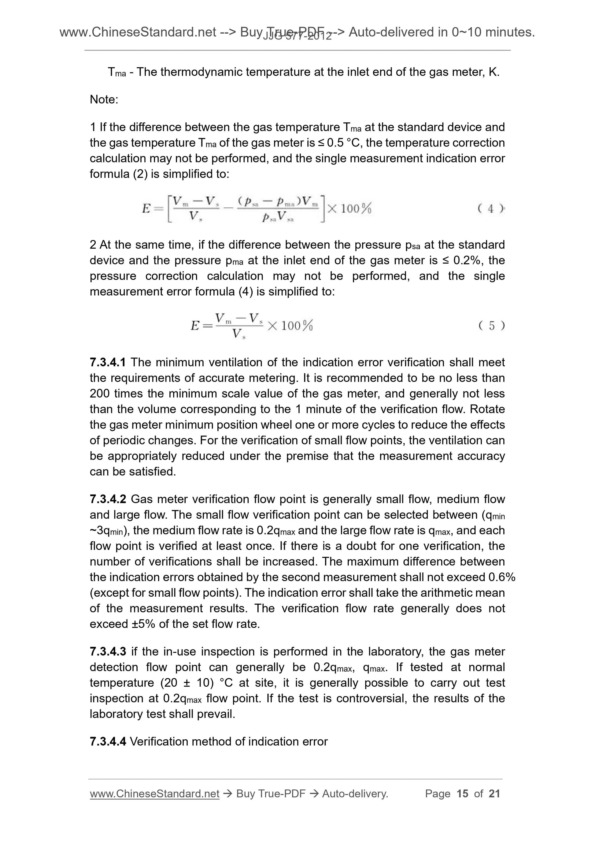
Tma - The thermodynamic temperature at the inlet end of the gas meter, K.
Note.
1 If the difference between the gas temperature Tma at the standard device and
the gas temperature Tma of the gas meter is ≤ 0.5 °C, the temperature correction
calculation may not be performed, and the single measurement indication error
formula (2) is simplified to.
2 At the same time, if the difference between the pressure psa at the standard
device and the pressure pma at the inlet end of the gas meter is ≤ 0.2%, the
pressure correction calculation may not be performed, and the single
measurement error formula (4) is simplified to.
7.3.4.1 The minimum ventilation of the indication error verification shall meet
the requirements of accurate metering. It is recommended to be no less than
200 times the minimum scale value of the gas meter, and generally not less
than the volume corresponding to the 1 minute of the verification flow. Rotate
the gas meter minimum position wheel one or more cycles to reduce the effects
of periodic changes. For the verification of small flow points, the ventilation can
be appropriately reduced under the premise that the measurement accuracy
can be satisfied.
7.3.4.2 Gas meter verification flow point is generally small flow, medium flow
and large flow. The small flow verification point can be selected between (qmin
~3qmin), the medium flow rate is 0.2qmax and the large flow rate is qmax, and each
flow point is verified at least once. If there is a doubt for one verification, the
number of verifications shall be increased. The maximum difference between
the indication errors obtained by the second measurement shall not exceed 0.6%
(except for small flow points)...
Get QUOTATION in 1-minute: Click JJG 577-2012
Historical versions: JJG 577-2012
Preview True-PDF (Reload/Scroll if blank)
JJG 577-2012: Verification Regulation of Diaphragm Gas Meters
JJG 577-2012
JJG
NATIONAL METROLOGY VERIFICATION REGULATION
OF THE PEOPLE’S REPUBLIC OF CHINA
Diaphragm gas meters
模式燃气表
ISSUED ON. SEPTEMBER 03, 2012
IMPLEMENTED ON. MARCH 03, 2013
Issued by. General Administration of Quality Supervision, Inspection and
Quarantine
Table of Contents
Introduction ... 4
1 Scope ... 5
2 Normative references ... 5
3 Terms and metering units ... 5
3.1 Terminology ... 5
3.2 Unit of measurement ... 7
4 Overview ... 7
4.1 Principle and structure... 7
4.2 Use ... 8
5 Metrological performance requirements ... 8
6 General technical requirements ... 8
6.1 Nameplates and markings ... 8
6.2 Appearance ... 9
6.3 Flow-rate range ... 9
6.4 Indicating device ... 10
6.5 Sealing ... 10
6.6 Pressure loss... 10
6.7 Ancillary devices ... 11
6.8 Safety performance ... 11
7 Metering instrument control ... 11
7.1 Verification conditions ... 11
7.2 Verification item ... 12
7.3 Verification method ... 13
7.4 Processing of verification results ... 18
7.5 Verification cycle ... 18
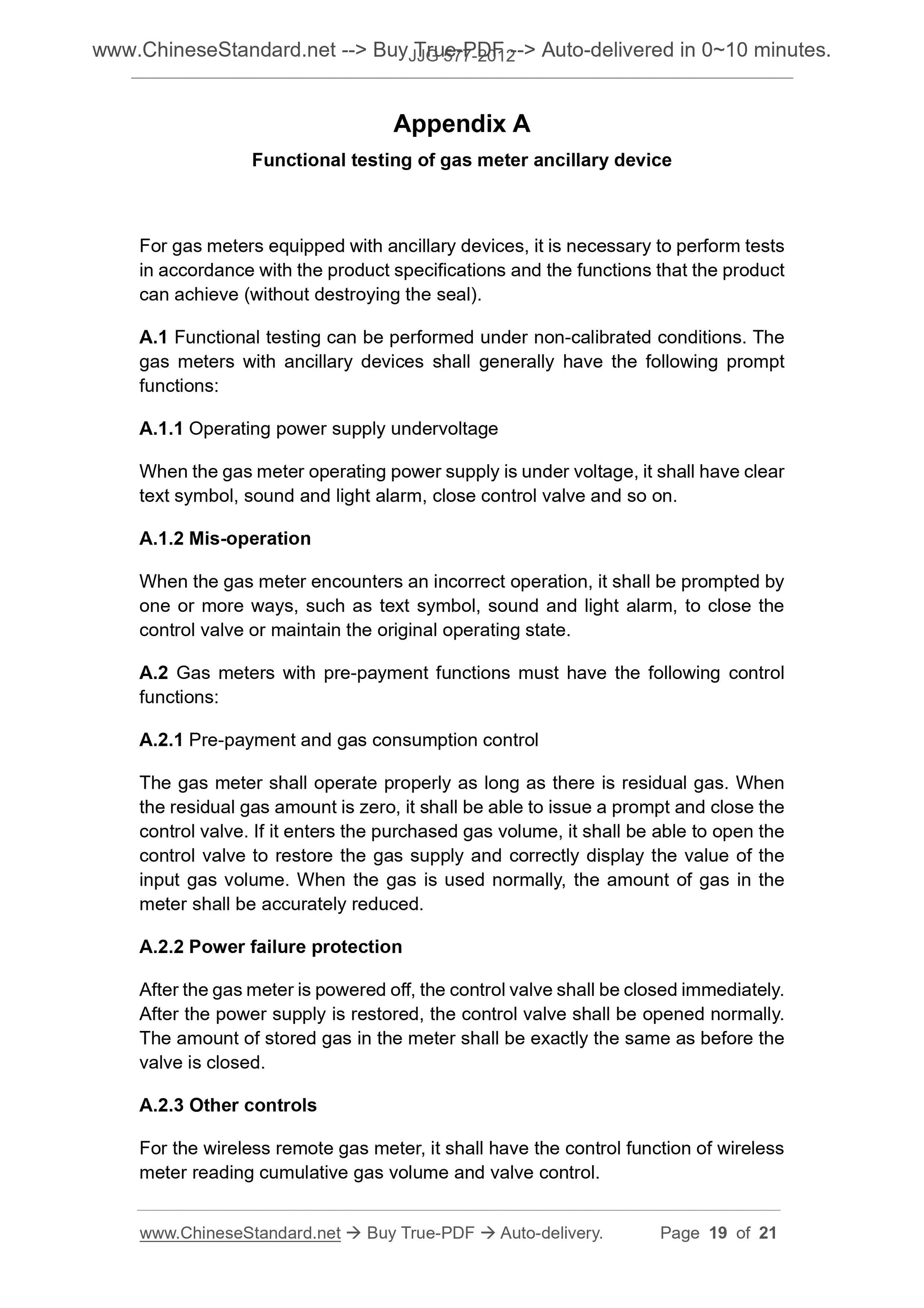
Appendix A Functional testing of gas meter ancillary device ... 19
Appendix B Information and format of verification certificate/verification result
notice inside page ... 21
Introduction
This regulation is the revision of the JJG 577-2005 “Diaphragm gas meters”
based on the national standard GB/T 6968-2011 “Membrane gas meters”,
international legal measurement organization’s (OIML) international
recommendation R137-1 and 2.2012 “Gas meter” as the technical basis, combined
with the status quo of China's membrane gas meter industry. It is equivalent to
national standards and international recommendations on major technical
indicators. In accordance with the needs of the work, JJ G577-2005 “Diaphragm
gas meters” is split into the verification regulation and the technical specification
of the type evaluation outline. As compared with the JJG 577-2005 version,
except for editorial changes, the main technical changes of this regulation are
as follows.
- CANCEL the metering level, USE the accuracy level representation;
- MODIFY the metering small flow point, which can be selected between qmin
~ 3qmin;
- MODIFY the counter technical requirements;
- MODIFY the flow range parameters of the gas meter;
- MODIFY the verification environment requirements;
- CANCEL the torque impact on performance requirements;
- MODIFY the minimum ventilation requirement during the indication error
test;
- ADD the specific detection method for inspection errors in use;
- MODIFY the format of the inside page of the verification certificate/
verification result notice;
- DELETE the Appendix A “Type evaluation test outline” from the original
regulations, separately FORMULATE the type evaluation test outline as a
national technical specification.
The previous versions of JJG 577-2005 were released as follows.
- JJG 333-83 Membrane household gas meter (for trial);
- JJG 577-88 Industrial gas meter (for trial);
- JJG 577-1994 Membrane gas meter.
Verification regulation of diaphragm gas meters
1 Scope
This regulation is applicable to the first verification, subsequent verification and
in-use inspection of diaphragm gas meters (hereinafter referred to as gas
meters).
2 Normative references
This regulation refers to the following documents.
JJF 1001-2011 General terms in metrology and their definitions
GB/T 6968-2011 Diaphragm gas meters
OIML R137-1 and 2.2012 Gas meters
OIML D11.2004 General requirements for electronic measuring instruments
EN 1359.1998 + A1.2006 Diaphragm gas meters
For dated references, only the dated version applies to this regulation; for
undated references, the latest version (including all amendments) applies to
this regulation.
3 Terms and metering units
3.1 Terminology
3.1.1
Maximum flow rate qmax
The upper flow limit of the gas meter that meets the metering performance
requirements.
3.1.2
Minimum flow-rate qmin
The lower flow limit of the gas meter that meets the metering performance
of ancillary device.
3.1.10
Gas meters equipped with ancillary devices
A gas meter equipped with ancillary device to achieve a predetermined
function. Ancillary devices typically include data for reading the base meter,
flow signal conversion and control units, and the like.
Note. Mechanical meters used by gas meters with ancillary devices are
generally referred to as base meter.
3.2 Unit of measurement
Volume unit. cubic meter, symbol m3; liter, symbol L; cubic decimeter, symbol
dm3.
Flow unit. cubic meters per hour, symbol m3/h.
Pressure unit. Pa [Pascal], Kilopascal, symbol Pa, kPa.
Temperature unit. Celsius, symbol °C.
4 Overview
4.1 Principle and structure
The gas meter is a volumetric gas flow meter that uses a flexible diaphragm
metering chamber to measure gas volume flow. Under the action of the
pressure difference, the gas is alternately entered into the metering chamber
through the distribution valve, and is filled to the gas outlet after being filled fully.
At the same time, the flexible diaphragm in the metering chamber is pushed to
reciprocate, and the circulation process of the inflation and exhaust is converted
into the corresponding gas volume flow by the conversion mechanism. Then it
is transmitted to the counter through the transmission mechanism to complete
the gas accumulation metering function.
The base meter is mainly composed of a casing, a diaphragm metering
chamber, a distribution valve, a link mechanism, an anti-reverse device, a
transmission mechanism, and a counter.
4.1.1 Anti-reverse device
The gas meter shall be equipped with means to prevent reversal. When the gas
Tma - The thermodynamic temperature at the inlet end of the gas meter, K.
Note.
1 If the difference between the gas temperature Tma at the standard device and
the gas temperature Tma of the gas meter is ≤ 0.5 °C, the temperature correction
calculation may not be performed, and the single measurement indication error
formula (2) is simplified to.
2 At the same time, if the difference between the pressure psa at the standard
device and the pressure pma at the inlet end of the gas meter is ≤ 0.2%, the
pressure correction calculation may not be performed, and the single
measurement error formula (4) is simplified to.
7.3.4.1 The minimum ventilation of the indication error verification shall meet
the requirements of accurate metering. It is recommended to be no less than
200 times the minimum scale value of the gas meter, and generally not less
than the volume corresponding to the 1 minute of the verification flow. Rotate
the gas meter minimum position wheel one or more cycles to reduce the effects
of periodic changes. For the verification of small flow points, the ventilation can
be appropriately reduced under the premise that the measurement accuracy
can be satisfied.
7.3.4.2 Gas meter verification flow point is generally small flow, medium flow
and large flow. The small flow verification point can be selected between (qmin
~3qmin), the medium flow rate is 0.2qmax and the large flow rate is qmax, and each
flow point is verified at least once. If there is a doubt for one verification, the
number of verifications shall be increased. The maximum difference between
the indication errors obtained by the second measurement shall not exceed 0.6%
(except for small flow points)...
Share