1
/
of
6
PayPal, credit cards. Download editable-PDF and invoice in 1 second!
JJG 801-2004 English PDF
JJG 801-2004 English PDF
Regular price
$170.00 USD
Regular price
Sale price
$170.00 USD
Unit price
/
per
Shipping calculated at checkout.
Couldn't load pickup availability
Delivery: 3 seconds. Download true-PDF + Invoice.
Get QUOTATION in 1-minute: Click JJG 801-2004
Historical versions: JJG 801-2004
Preview True-PDF (Reload/Scroll if blank)
JJG 801-2004: Verification Regulation of Chemiluminescent NO/NOx Analyzers
JJG 801-2004
JJG
NATIONAL METROLOGICAL VERIFICATION REGULATIONS
OF THE PEOPLE’S REPUBLIC OF CHINA
Chemiluminescent NO/NOx Analyzers
ISSUED ON: NOVEMBER 09, 2004
IMPLEMENTED ON: MAY 09, 2005
Issued by: General Administration of Quality Supervision, Inspection and
Quarantine of the People's Republic of China
Table of Contents
1 Scope ... 5
2 Overview ... 5
3 Metering performance requirements ... 5
4 General technical requirements ... 6
4.1 Appearance and power-on inspection ... 6
4.2 Insulation resistance... 6
4.3 Insulation strength ... 6
5 Measuring instrument control ... 6
5.1 Verification conditions ... 7
5.2 Verification items ... 7
5.3 Verification methods ... 8
5.4 Processing of verification results ... 10
5.5 Verification cycle ... 10
Annex A Description of reference materials ... 11
Annex B Inner page format of verification certificate and verification result notice
... 12
Annex C Verification record format ... 13
Carbon Monoxide and Carbon Dioxide Infrared Gas
Analyzer
1 Scope
This Standard applies to the initial verification, subsequent verification and in-
use inspection of chemiluminescence nitrogen oxide analyzer.
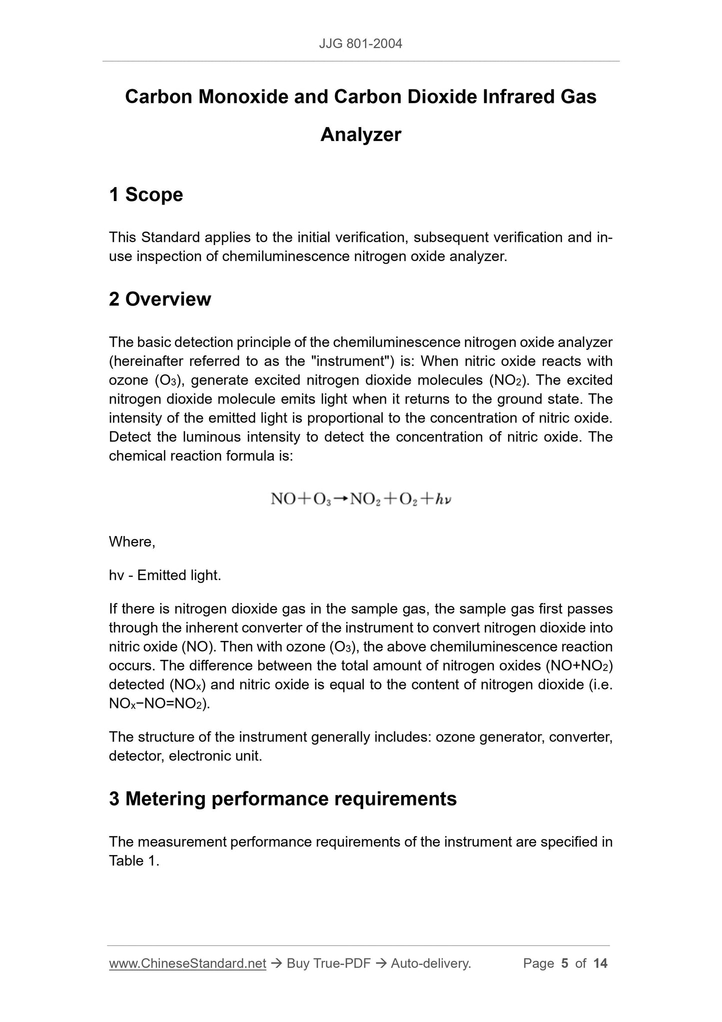
2 Overview
The basic detection principle of the chemiluminescence nitrogen oxide analyzer
(hereinafter referred to as the "instrument") is: When nitric oxide reacts with
ozone (O3), generate excited nitrogen dioxide molecules (NO2). The excited
nitrogen dioxide molecule emits light when it returns to the ground state. The
intensity of the emitted light is proportional to the concentration of nitric oxide.
Detect the luminous intensity to detect the concentration of nitric oxide. The
chemical reaction formula is:
Where,
hv - Emitted light.
If there is nitrogen dioxide gas in the sample gas, the sample gas first passes
through the inherent converter of the instrument to convert nitrogen dioxide into
nitric oxide (NO). Then with ozone (O3), the above chemiluminescence reaction
occurs. The difference between the total amount of nitrogen oxides (NO+NO2)
detected (NOx) and nitric oxide is equal to the content of nitrogen dioxide (i.e.
NOx−NO=NO2).
The structure of the instrument generally includes: ozone generator, converter,
detector, electronic unit.
3 Metering performance requirements
The measurement performance requirements of the instrument are specified in
Table 1.
5.3 Verification methods
5.3.1 Appearance and power-on inspection
Use visual inspection and hand feel method according to requirements of 4.1.1
and 4.1.2.
5.3.2 Insulation resistance measurement
The tested instrument is not connected to the power supply. Turn on its power
switch. Connect one terminal of the insulation resistance meter to the phase
and middle connection lines of the power plug. The other terminal is connected
to the ground terminal of the instrument. Use the insulation resistance meter to
measure the insulation resistance of the tested instrument.
5.3.3 Insulation strength measurement
The tested instrument is not connected to the power supply. Turn on its power
switch. Connect the two wires of the insulation strength measuring instrument
to the phase wire (or neutral wire) of the power plug of the tested instrument
and the chassis. Make the voltage rise steadily to 1500V. Maintain 1min. Then
make the voltage drop steadily to 0V. No breakdown and arcing shall occur
during the test.
5.3.4 Calibration before verification
Power on the instrument to warm up for at least 1.5h. The total flow rate
monitored by the vent flow meter is greater than the flow rate required by the
instructions. Access zero-point gas first. Adjust zero point. Access NO standard
gas that is about 85% of the range. After the indicated value stabilizes, adjust
the instrument's NO and NOx indicated values to be consistent with the
standard values.
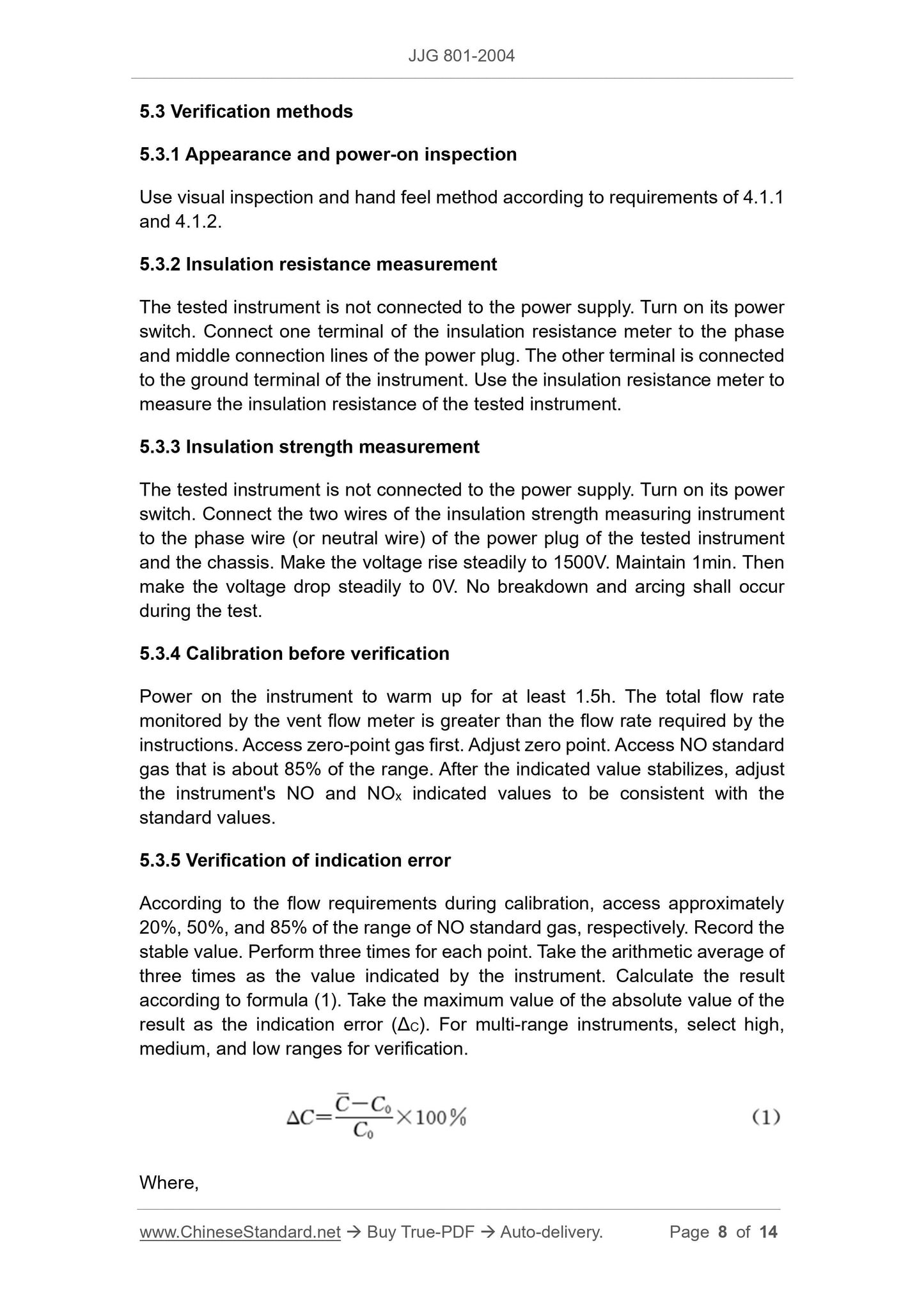
5.3.5 Verification of indication error
According to the flow requirements during calibration, access approximately
20%, 50%, and 85% of the range of NO standard gas, respectively. Record the
stable value. Perform three times for each point. Take the arithmetic average of
three times as the value indicated by the instrument. Calculate the result
according to formula (1). Take the maximum value of the absolute value of the
result as the indication error (ΔC). For multi-range instruments, select high,
medium, and low ranges for verification.
Where,
Where,
- Average NO2 of three measurements;
C0 - NO2 mixed gas concentration.
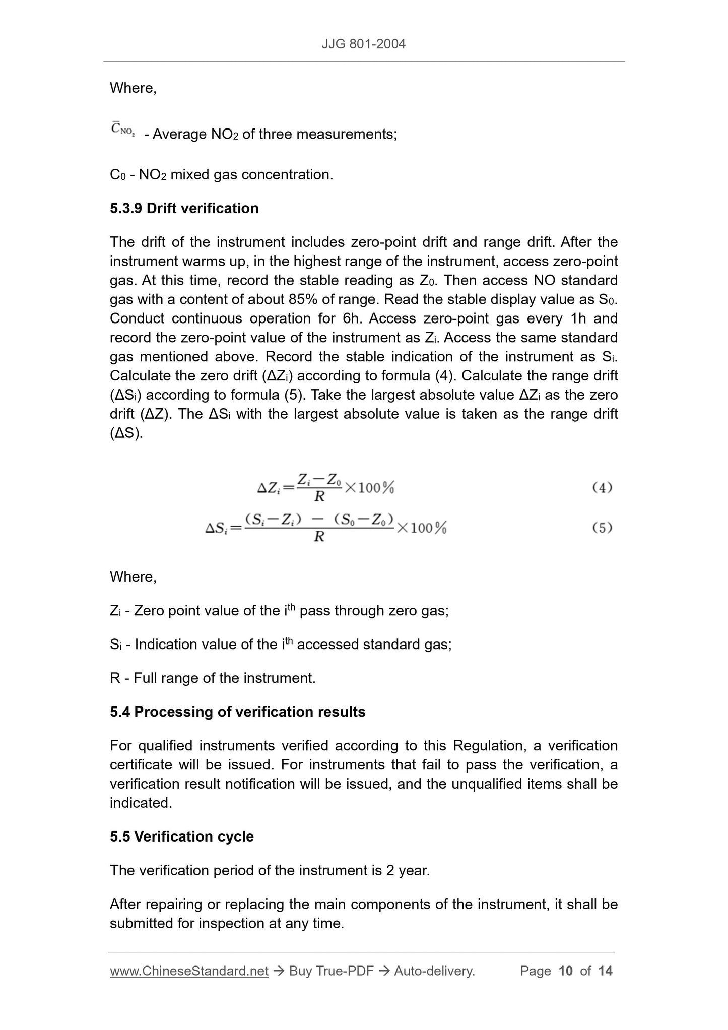
5.3.9 Drift verification
The drift of the instrument includes zero-point drift and range drift. After the
instrument warms up, in the highest range of the instrument, access zero-point
gas. At this time, record the stable reading as Z0. Then access NO standard
gas with a content of about 85% of range. Read the stable display value as S0.
Conduct continuous operation for 6h. Access zero-point gas every 1h and
record the zero-point value of the instrument as Zi. Access the same standard
gas mentioned above. Record the stable indication of the instrument as Si.
Calculate the zero drift (ΔZi) according to formula (4). Calculate the range drift
(ΔSi) according to formula (5). Take the largest absolute value ΔZi as the zero
drift (ΔZ). The ΔSi with the largest absolute value is taken as the range drift
(ΔS).
Where,
Zi - Zero point value of the ith pass through zero gas;
Si - Indication value of the ith accessed standard gas;
R - Full range of the instrument.
5.4 Processing of verification results
For qualified instruments verified according to this Regulation, a verification
certificate will be issued. For instruments that fail to pass the verification, a
verification result notification will be issued, and the unqualified items shall be
indicated.
5.5 Verification cycle
The verification period of the instrument is 2 year.
After repairing or replacing the main components of the instrument, it shall be
submitted for inspection at any time.
Annex A
Description of reference materials
Because the use environment of the instrument is different, the range of the
instrument is different. Quite a few chemiluminescence nitrogen oxide
analyzers have a very low range of use, which generally is less than 10×10-6.
Therefore, the gas standard substance used in the verification can also be
configured with low-concentration standard gas using the ISO recognized mass
flow dynamic gas distribution device. However, the high-concentration standard
gas used in dynamic gas distribution must be traced to a national certified
standard material with an uncertainty of 1% (k=3).
The current typical standard gas dilution device is based on the above principle.
According to the needs of the inspected instrument, use high-purity nitrogen as
diluent gas. Dilute high-concentration gas reference materials. Various
standard gases with 10-8~10-2 content can be prepared. Its main technical
performances are as follows:
1) Flow range: (10/2000/3000/5000) mL/min (optional);
2) Flow indication error limit: ±0.5%;
3) Time required to convert the concentration: < 60s.
Get QUOTATION in 1-minute: Click JJG 801-2004
Historical versions: JJG 801-2004
Preview True-PDF (Reload/Scroll if blank)
JJG 801-2004: Verification Regulation of Chemiluminescent NO/NOx Analyzers
JJG 801-2004
JJG
NATIONAL METROLOGICAL VERIFICATION REGULATIONS
OF THE PEOPLE’S REPUBLIC OF CHINA
Chemiluminescent NO/NOx Analyzers
ISSUED ON: NOVEMBER 09, 2004
IMPLEMENTED ON: MAY 09, 2005
Issued by: General Administration of Quality Supervision, Inspection and
Quarantine of the People's Republic of China
Table of Contents
1 Scope ... 5
2 Overview ... 5
3 Metering performance requirements ... 5
4 General technical requirements ... 6
4.1 Appearance and power-on inspection ... 6
4.2 Insulation resistance... 6
4.3 Insulation strength ... 6
5 Measuring instrument control ... 6
5.1 Verification conditions ... 7
5.2 Verification items ... 7
5.3 Verification methods ... 8
5.4 Processing of verification results ... 10
5.5 Verification cycle ... 10
Annex A Description of reference materials ... 11
Annex B Inner page format of verification certificate and verification result notice
... 12
Annex C Verification record format ... 13
Carbon Monoxide and Carbon Dioxide Infrared Gas
Analyzer
1 Scope
This Standard applies to the initial verification, subsequent verification and in-
use inspection of chemiluminescence nitrogen oxide analyzer.
2 Overview
The basic detection principle of the chemiluminescence nitrogen oxide analyzer
(hereinafter referred to as the "instrument") is: When nitric oxide reacts with
ozone (O3), generate excited nitrogen dioxide molecules (NO2). The excited
nitrogen dioxide molecule emits light when it returns to the ground state. The
intensity of the emitted light is proportional to the concentration of nitric oxide.
Detect the luminous intensity to detect the concentration of nitric oxide. The
chemical reaction formula is:
Where,
hv - Emitted light.
If there is nitrogen dioxide gas in the sample gas, the sample gas first passes
through the inherent converter of the instrument to convert nitrogen dioxide into
nitric oxide (NO). Then with ozone (O3), the above chemiluminescence reaction
occurs. The difference between the total amount of nitrogen oxides (NO+NO2)
detected (NOx) and nitric oxide is equal to the content of nitrogen dioxide (i.e.
NOx−NO=NO2).
The structure of the instrument generally includes: ozone generator, converter,
detector, electronic unit.
3 Metering performance requirements
The measurement performance requirements of the instrument are specified in
Table 1.
5.3 Verification methods
5.3.1 Appearance and power-on inspection
Use visual inspection and hand feel method according to requirements of 4.1.1
and 4.1.2.
5.3.2 Insulation resistance measurement
The tested instrument is not connected to the power supply. Turn on its power
switch. Connect one terminal of the insulation resistance meter to the phase
and middle connection lines of the power plug. The other terminal is connected
to the ground terminal of the instrument. Use the insulation resistance meter to
measure the insulation resistance of the tested instrument.
5.3.3 Insulation strength measurement
The tested instrument is not connected to the power supply. Turn on its power
switch. Connect the two wires of the insulation strength measuring instrument
to the phase wire (or neutral wire) of the power plug of the tested instrument
and the chassis. Make the voltage rise steadily to 1500V. Maintain 1min. Then
make the voltage drop steadily to 0V. No breakdown and arcing shall occur
during the test.
5.3.4 Calibration before verification
Power on the instrument to warm up for at least 1.5h. The total flow rate
monitored by the vent flow meter is greater than the flow rate required by the
instructions. Access zero-point gas first. Adjust zero point. Access NO standard
gas that is about 85% of the range. After the indicated value stabilizes, adjust
the instrument's NO and NOx indicated values to be consistent with the
standard values.
5.3.5 Verification of indication error
According to the flow requirements during calibration, access approximately
20%, 50%, and 85% of the range of NO standard gas, respectively. Record the
stable value. Perform three times for each point. Take the arithmetic average of
three times as the value indicated by the instrument. Calculate the result
according to formula (1). Take the maximum value of the absolute value of the
result as the indication error (ΔC). For multi-range instruments, select high,
medium, and low ranges for verification.
Where,
Where,
- Average NO2 of three measurements;
C0 - NO2 mixed gas concentration.
5.3.9 Drift verification
The drift of the instrument includes zero-point drift and range drift. After the
instrument warms up, in the highest range of the instrument, access zero-point
gas. At this time, record the stable reading as Z0. Then access NO standard
gas with a content of about 85% of range. Read the stable display value as S0.
Conduct continuous operation for 6h. Access zero-point gas every 1h and
record the zero-point value of the instrument as Zi. Access the same standard
gas mentioned above. Record the stable indication of the instrument as Si.
Calculate the zero drift (ΔZi) according to formula (4). Calculate the range drift
(ΔSi) according to formula (5). Take the largest absolute value ΔZi as the zero
drift (ΔZ). The ΔSi with the largest absolute value is taken as the range drift
(ΔS).
Where,
Zi - Zero point value of the ith pass through zero gas;
Si - Indication value of the ith accessed standard gas;
R - Full range of the instrument.
5.4 Processing of verification results
For qualified instruments verified according to this Regulation, a verification
certificate will be issued. For instruments that fail to pass the verification, a
verification result notification will be issued, and the unqualified items shall be
indicated.
5.5 Verification cycle
The verification period of the instrument is 2 year.
After repairing or replacing the main components of the instrument, it shall be
submitted for inspection at any time.
Annex A
Description of reference materials
Because the use environment of the instrument is different, the range of the
instrument is different. Quite a few chemiluminescence nitrogen oxide
analyzers have a very low range of use, which generally is less than 10×10-6.
Therefore, the gas standard substance used in the verification can also be
configured with low-concentration standard gas using the ISO recognized mass
flow dynamic gas distribution device. However, the high-concentration standard
gas used in dynamic gas distribution must be traced to a national certified
standard material with an uncertainty of 1% (k=3).
The current typical standard gas dilution device is based on the above principle.
According to the needs of the inspected instrument, use high-purity nitrogen as
diluent gas. Dilute high-concentration gas reference materials. Various
standard gases with 10-8~10-2 content can be prepared. Its main technical
performances are as follows:
1) Flow range: (10/2000/3000/5000) mL/min (optional);
2) Flow indication error limit: ±0.5%;
3) Time required to convert the concentration: < 60s.
Share