


1
/
of
9
PayPal, credit cards. Download editable-PDF and invoice in 1 second!
JJG 879-2015 English PDF
JJG 879-2015 English PDF
Regular price
$640.00 USD
Regular price
Sale price
$640.00 USD
Unit price
/
per
Shipping calculated at checkout.
Couldn't load pickup availability
Delivery: 3 seconds. Download true-PDF + Invoice.
Get QUOTATION in 1-minute: Click JJG 879-2015
Historical versions: JJG 879-2015
Preview True-PDF (Reload/Scroll if blank)
JJG 879-2015: Ultraviolet Radiometers
JJG 879-2015
JJF
NATIONAL METROLOGY VERIFICATION REGULATION
OF THE PEOPLE’S REPUBLIC OF CHINA
Ultraviolet Radiometers
紫外辐射照度计
ISSUED ON: DECEMBER 07, 2015
IMPLEMENTED ON: JUNE 07, 2016
Issued by: General Administration of Quality Supervision, Inspection and
Quarantine of the People's Republic of China
Table of Contents
Introduction ... 5
1 Scope ... 6
2 Overview ... 6
3 Metrology performance requirements ... 7
3.1 Spectral response and band division ... 7
3.2 Zero-value error (full scale FS) ... 7
3.3 Long-wave response error... 7
3.4 Cosine characteristic (directional response) error ... 8
3.5 Nonlinear error ... 8
3.6 Shifting error ... 8
3.7 Fatigue error ... 9
3.8 Relative indication error ... 9
4 General technical requirements ... 9
4.1 Appearance ... 9
4.2 Optical attenuator ... 9
4.3 Spectral response range... 9
5 Measuring instrument control ... 10
5.1 Verification conditions ... 10
5.2 Verification items ... 11
5.3 Verification methods ... 12
5.4 Processing of verification results ... 19
5.5 Verification cycle ... 19
Annex A Format of the inner page of the verification certificate and verification result
notice ... 20
Annex B Original records of verification ... 21
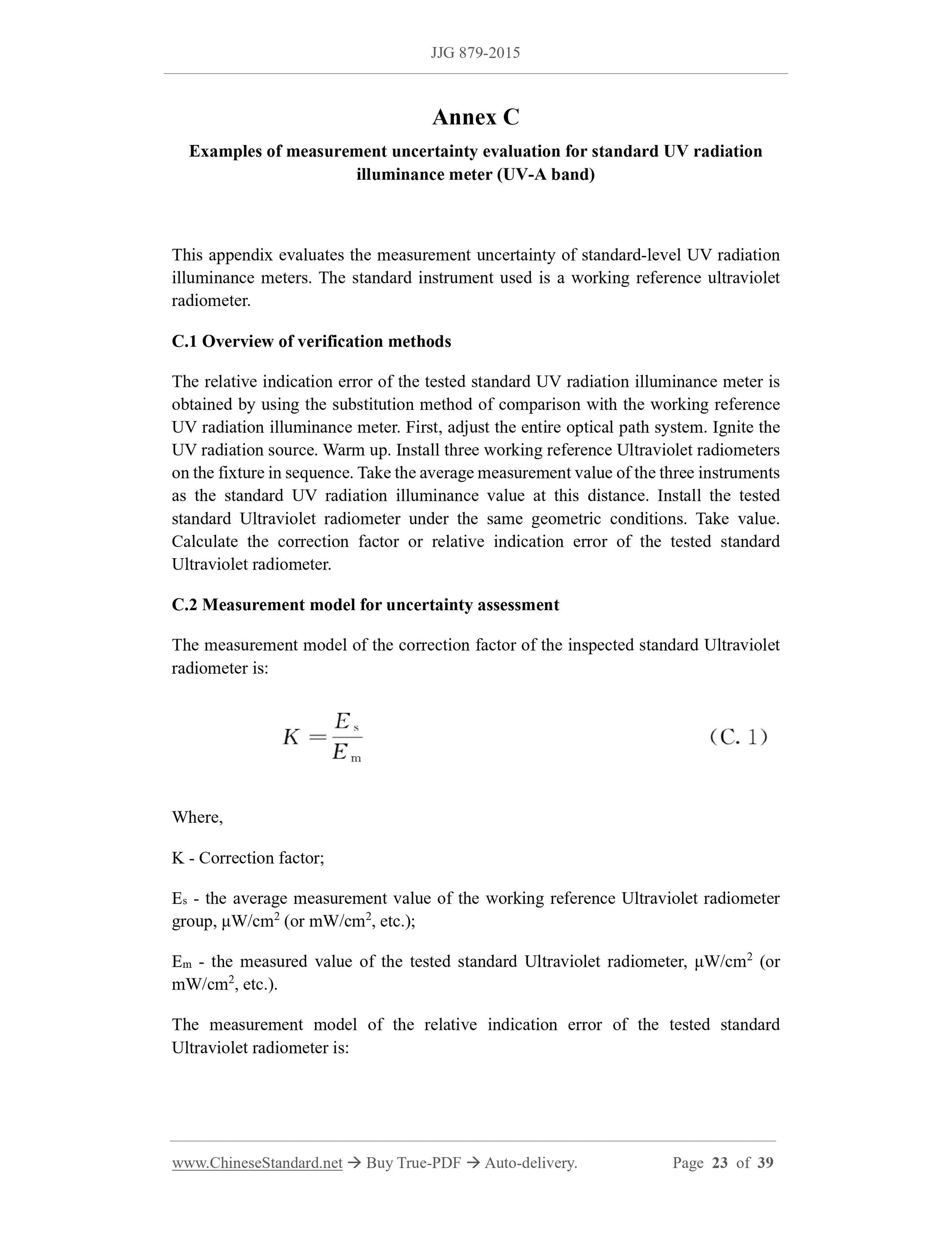
Annex C Examples of measurement uncertainty evaluation for standard UV radiation
illuminance meter (UV-A band) ... 23
Annex D Examples of measurement uncertainty evaluation for level-1 Ultraviolet
radiometer (UV-A band) ... 32
Verification Regulation of Ultraviolet Radiometers
1 Scope
This Regulation applies to initial verification, subsequent verification and in-use
inspection for standard-level, level-1 and level-2 ultraviolet radiometers that comply
with the division of ultraviolet radiation UV-A, UV-B, UV-C, UV-A1, UV-365, UV-310,
UV-254 bands.
2 Overview
The International Commission on Illumination (CIE) divides ultraviolet radiation into
three bands: UV-A (315nm~400nm), UV-B (280nm~315nm) and UV-C
(100nm~280nm). Since ultraviolet radiation of 100nm~200nm is strongly absorbed in
the air, for the UV-C band, this Regulation only considers the wavelength range of
200nm~280nm.
Ultraviolet radiometer that complies with the ultraviolet radiation UV-A, UV-B, UV-C,
UV-A1, UV-365, UV-310, and UV-254 band divisions is an instrument used to measure
ultraviolet radiometer. It is widely used in fields such as medical treatment, epidemic
prevention, optoelectronics, flaw detection, electric light sources, chemical industry,
building materials, meteorology, material aging and aerospace. It mainly consists of
detector, amplifier circuit and display instrument. The detector generally consists of a
photodetector device, a filter (bandpass glass or interference filter) and a diffuser.
Figure 1 is a schematic diagram of the general structure of an ultraviolet radiometer
detector.
provisions of 3.1.
5 Measuring instrument control
Measuring instrument control includes initial verification, subsequent verification and
in-use inspection.
5.1 Verification conditions
5.1.1 Equipment for verification
5.1.1.1 UV radiation illuminance standard device
There are three ultraviolet radiometer standard devices for each band.
The standard device for verifying the standard ultraviolet radiometer shall use the
working reference ultraviolet radiometer. The standard device for verifying the level-1
ultraviolet radiometer shall use a standard-level ultraviolet radiometer (or a working
reference ultraviolet radiometer). The standard device for verifying the level-2
ultraviolet radiometer shall use the level-1 ultraviolet radiometer (or standard-level
ultraviolet radiometer, working reference ultraviolet radiometer). See 3.1~3.8 for the
measurement performance requirements of standard-level and level-1 ultraviolet
radiometers. For the measurement performance requirements of the working reference
ultraviolet radiometer, see JJG 755.
5.1.1.2 UV radiation source
There is one ultraviolet radiation source for verification in different wavebands.
The ultraviolet radiation sources for verification of UV-A, UV-A1 and UV-365 bands
use black light high-pressure mercury lamps, high-pressure mercury lamps, UV-A
fluorescent ultraviolet lamps, metal halide lamps, LED light sources (365nm), etc. UV-
B and UV-310 bands use UV-B fluorescent UV lamps. The UV-C band uses low-
pressure mercury lamps. In order to reduce the spectral mismatch error, the UV
radiation source used for verification shall have the same spectral distribution as the
UV radiation source used to calibrate the UV radiation illumination standard.
The UV radiation change rate of various UV radiation sources does not exceed ±1.0%
within 15 min. The actual usable area of the UV radiation source shall be larger than
the effective receiving area of the detector. Its unevenness does not exceed ±2.0%.
The UV radiation source is powered by a regulated power supply. Voltage instability
does not exceed ±2.0%/h.
5.1.1.3 Measurement device for comparison of UV radiation illuminance
The long-wavelength response error of the ultraviolet radiometer shall comply with the
provisions of 3.3.
5.3.3 Cosine characteristic (directional response) error
Install the detector of the ultraviolet radiometer on a rotating platform with a dial, so
that the rotation axis of the platform passes through the center of the detector's receiving
surface. Adjust the rotating platform so that the normal line passing through the center
of the detection surface is consistent with the normal line of the ultraviolet radiation
source.
Several apertures are placed between the UV radiation source and the detector. Adjust
the position of each diaphragm so that it does not block the light radiation from the
ultraviolet radiation source to the receiving surface. The distance between the UV
radiation source and the detector is greater than 15 times the maximum linear dimension
of the UV radiation source's luminous surface or the detector's receiving surface (for
example: the maximum linear dimension of a circular luminous surface is the diameter
of the circle, and the maximum linear dimension of a rectangular luminous surface are
the diagonals of the rectangle).
Ignite the UV radiation source. Preheat for 30 min. Then turn the platform to the left so
that the ultraviolet radiometer displays a certain value (50%~80% of the maximum
value). Note the turntable angle at this time. Then turn the platform to the right to make
the display value of the ultraviolet radiometer reach the above display value. Note the
angle of the turntable at this time. The average of these two angles is the normal
irradiance incidence angle (i.e., 0°). Record the display value of the ultraviolet
radiometer at this angle. Then turn the platform. Record the display values of the
ultraviolet radiometer when the angles are ±5°, ±10°, ±15°, ±20°… ±85°.
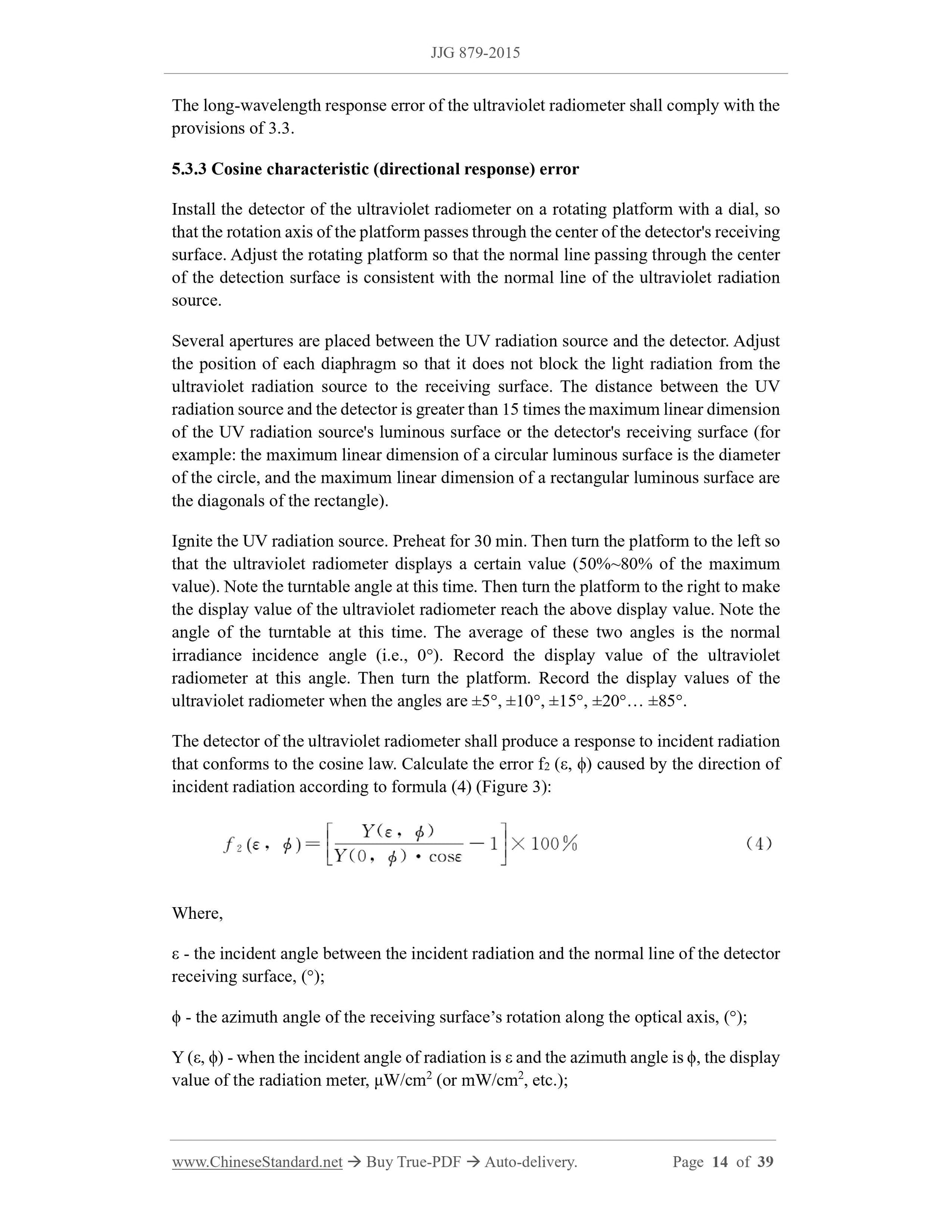
The detector of the ultraviolet radiometer shall produce a response to incident radiation
that conforms to the cosine law. Calculate the error f2 (ε, ϕ) caused by the direction of
incident radiation according to formula (4) (Figure 3):
Where,
ε - the incident angle between the incident radiation and the normal line of the detector
receiving surface, (°);
ϕ - the azimuth angle of the receiving surface’s rotation along the optical axis, (°);
Y (ε, ϕ) - when the incident angle of radiation is ε and the azimuth angle is ϕ, the display
value of the radiation meter, μW/cm2 (or mW/cm2, etc.)...
Get QUOTATION in 1-minute: Click JJG 879-2015
Historical versions: JJG 879-2015
Preview True-PDF (Reload/Scroll if blank)
JJG 879-2015: Ultraviolet Radiometers
JJG 879-2015
JJF
NATIONAL METROLOGY VERIFICATION REGULATION
OF THE PEOPLE’S REPUBLIC OF CHINA
Ultraviolet Radiometers
紫外辐射照度计
ISSUED ON: DECEMBER 07, 2015
IMPLEMENTED ON: JUNE 07, 2016
Issued by: General Administration of Quality Supervision, Inspection and
Quarantine of the People's Republic of China
Table of Contents
Introduction ... 5
1 Scope ... 6
2 Overview ... 6
3 Metrology performance requirements ... 7
3.1 Spectral response and band division ... 7
3.2 Zero-value error (full scale FS) ... 7
3.3 Long-wave response error... 7
3.4 Cosine characteristic (directional response) error ... 8
3.5 Nonlinear error ... 8
3.6 Shifting error ... 8
3.7 Fatigue error ... 9
3.8 Relative indication error ... 9
4 General technical requirements ... 9
4.1 Appearance ... 9
4.2 Optical attenuator ... 9
4.3 Spectral response range... 9
5 Measuring instrument control ... 10
5.1 Verification conditions ... 10
5.2 Verification items ... 11
5.3 Verification methods ... 12
5.4 Processing of verification results ... 19
5.5 Verification cycle ... 19
Annex A Format of the inner page of the verification certificate and verification result
notice ... 20
Annex B Original records of verification ... 21
Annex C Examples of measurement uncertainty evaluation for standard UV radiation
illuminance meter (UV-A band) ... 23
Annex D Examples of measurement uncertainty evaluation for level-1 Ultraviolet
radiometer (UV-A band) ... 32
Verification Regulation of Ultraviolet Radiometers
1 Scope
This Regulation applies to initial verification, subsequent verification and in-use
inspection for standard-level, level-1 and level-2 ultraviolet radiometers that comply
with the division of ultraviolet radiation UV-A, UV-B, UV-C, UV-A1, UV-365, UV-310,
UV-254 bands.
2 Overview
The International Commission on Illumination (CIE) divides ultraviolet radiation into
three bands: UV-A (315nm~400nm), UV-B (280nm~315nm) and UV-C
(100nm~280nm). Since ultraviolet radiation of 100nm~200nm is strongly absorbed in
the air, for the UV-C band, this Regulation only considers the wavelength range of
200nm~280nm.
Ultraviolet radiometer that complies with the ultraviolet radiation UV-A, UV-B, UV-C,
UV-A1, UV-365, UV-310, and UV-254 band divisions is an instrument used to measure
ultraviolet radiometer. It is widely used in fields such as medical treatment, epidemic
prevention, optoelectronics, flaw detection, electric light sources, chemical industry,
building materials, meteorology, material aging and aerospace. It mainly consists of
detector, amplifier circuit and display instrument. The detector generally consists of a
photodetector device, a filter (bandpass glass or interference filter) and a diffuser.
Figure 1 is a schematic diagram of the general structure of an ultraviolet radiometer
detector.
provisions of 3.1.
5 Measuring instrument control
Measuring instrument control includes initial verification, subsequent verification and
in-use inspection.
5.1 Verification conditions
5.1.1 Equipment for verification
5.1.1.1 UV radiation illuminance standard device
There are three ultraviolet radiometer standard devices for each band.
The standard device for verifying the standard ultraviolet radiometer shall use the
working reference ultraviolet radiometer. The standard device for verifying the level-1
ultraviolet radiometer shall use a standard-level ultraviolet radiometer (or a working
reference ultraviolet radiometer). The standard device for verifying the level-2
ultraviolet radiometer shall use the level-1 ultraviolet radiometer (or standard-level
ultraviolet radiometer, working reference ultraviolet radiometer). See 3.1~3.8 for the
measurement performance requirements of standard-level and level-1 ultraviolet
radiometers. For the measurement performance requirements of the working reference
ultraviolet radiometer, see JJG 755.
5.1.1.2 UV radiation source
There is one ultraviolet radiation source for verification in different wavebands.
The ultraviolet radiation sources for verification of UV-A, UV-A1 and UV-365 bands
use black light high-pressure mercury lamps, high-pressure mercury lamps, UV-A
fluorescent ultraviolet lamps, metal halide lamps, LED light sources (365nm), etc. UV-
B and UV-310 bands use UV-B fluorescent UV lamps. The UV-C band uses low-
pressure mercury lamps. In order to reduce the spectral mismatch error, the UV
radiation source used for verification shall have the same spectral distribution as the
UV radiation source used to calibrate the UV radiation illumination standard.
The UV radiation change rate of various UV radiation sources does not exceed ±1.0%
within 15 min. The actual usable area of the UV radiation source shall be larger than
the effective receiving area of the detector. Its unevenness does not exceed ±2.0%.
The UV radiation source is powered by a regulated power supply. Voltage instability
does not exceed ±2.0%/h.
5.1.1.3 Measurement device for comparison of UV radiation illuminance
The long-wavelength response error of the ultraviolet radiometer shall comply with the
provisions of 3.3.
5.3.3 Cosine characteristic (directional response) error
Install the detector of the ultraviolet radiometer on a rotating platform with a dial, so
that the rotation axis of the platform passes through the center of the detector's receiving
surface. Adjust the rotating platform so that the normal line passing through the center
of the detection surface is consistent with the normal line of the ultraviolet radiation
source.
Several apertures are placed between the UV radiation source and the detector. Adjust
the position of each diaphragm so that it does not block the light radiation from the
ultraviolet radiation source to the receiving surface. The distance between the UV
radiation source and the detector is greater than 15 times the maximum linear dimension
of the UV radiation source's luminous surface or the detector's receiving surface (for
example: the maximum linear dimension of a circular luminous surface is the diameter
of the circle, and the maximum linear dimension of a rectangular luminous surface are
the diagonals of the rectangle).
Ignite the UV radiation source. Preheat for 30 min. Then turn the platform to the left so
that the ultraviolet radiometer displays a certain value (50%~80% of the maximum
value). Note the turntable angle at this time. Then turn the platform to the right to make
the display value of the ultraviolet radiometer reach the above display value. Note the
angle of the turntable at this time. The average of these two angles is the normal
irradiance incidence angle (i.e., 0°). Record the display value of the ultraviolet
radiometer at this angle. Then turn the platform. Record the display values of the
ultraviolet radiometer when the angles are ±5°, ±10°, ±15°, ±20°… ±85°.
The detector of the ultraviolet radiometer shall produce a response to incident radiation
that conforms to the cosine law. Calculate the error f2 (ε, ϕ) caused by the direction of
incident radiation according to formula (4) (Figure 3):
Where,
ε - the incident angle between the incident radiation and the normal line of the detector
receiving surface, (°);
ϕ - the azimuth angle of the receiving surface’s rotation along the optical axis, (°);
Y (ε, ϕ) - when the incident angle of radiation is ε and the azimuth angle is ϕ, the display
value of the radiation meter, μW/cm2 (or mW/cm2, etc.)...
Share