1
/
of
9
PayPal, credit cards. Download editable-PDF & invoice in 1 second!
QC/T 1076-2017 English PDF (QCT1076-2017)
QC/T 1076-2017 English PDF (QCT1076-2017)
Regular price
$150.00 USD
Regular price
Sale price
$150.00 USD
Unit price
/
per
Shipping calculated at checkout.
Couldn't load pickup availability
Delivery: 3 seconds. Download true-PDF + Invoice.
Get QUOTATION in 1-minute: Click QC/T 1076-2017
Historical versions: QC/T 1076-2017
Preview True-PDF (Reload/Scroll if blank)
QC/T 1076-2017: Performance requirements and testing methods for continuously variable transmission
QC/T 1076-2017
AUTOMOTIVE INDUSTRY STANDARD
OF THE PEOPLE’S REPUBLIC OF CHINA
ICS 43.040.50
T 21
Performance requirements and testing methods for
continuously variable transmission
ISSUED ON: APRIL 12, 2017
IMPLEMENTED ON: OCTOBER 1, 2017
Issued by: Ministry of Industry and Information Technology of the
People’s Republic of China.
Table of Contents
Foreword ... 7
1 Scope ... 8
2 Normative references ... 8
3 Terms and definitions ... 9
4 Testing requirements and performance requirements ... 10
5 Testing methods ... 13
Performance requirements and testing methods for
continuously variable transmission
1 Scope
This Standard specifies the performance requirements and testing methods
for continuously variable transmissions (CVTs) for M1 vehicles.
This Standard applies to the M1 vehicles equipped with CVTs, while N1
vehicles equipped with CVTs and M2 vehicles under 3,500kg may be
implemented in accordance with this Standard.
2 Normative references
The following documents are essential for the application of this Standard.
For dated references, only the dated editions apply to this Standard. For
undated references, the latest editions (including all amendments) apply to
this Standard.
GB 15089 Classification of power-driven vehicle and trailers
GB 18352.5-2013 Limits and measurement methods for emissions from
light-duty vehicles (CHINA 5)
GB 19233 Measurement methods of fuel consumption for light-duty
vehicles
QC/T 465 Automotive mechanical transmission terminology and definition
ECE R10 Rev. 3 Uniform provisions concerning the approval of: vehicles
with regard to electromagnetic compatibility
ISO 11451-2 Road vehicles - Vehicle test methods for electrical
disturbances from narrowband radiated electromagnetic energy - Part 2:
Off-vehicle radiation sources
ISO 11452-4 Road vehicles - Vehicle test methods for electrical
disturbances from narrowband radiated electromagnetic energy - Part 4:
Bulk current injection (BCI)
3.11 Starting device
A device that is coupled between the engine and the transmission to transfer
engine torque to the transmission, such as a torque converter, a friction clutch,
etc.
3.12 Lock up
A connection state where the speed difference between input and output of
the starting device is 0.
3.13 Optimal fuel consumption curve
A curve connecting the lowest effective fuel consumption rate under different
operating conditions of the engine.
4 Testing requirements and performance
requirements
4.1 Testing requirements
4.1.1 Testing conditions
4.1.1.1 Environment
During the test, the temperature in the test chamber shall be 288K to 308K
(15°C to 35°C), the relative humidity shall be 20% to 60%, and the altitude
shall not exceed 1,000m.
4.1.1.2 Transmission oil
The transmission oil specified by the transmission manufacturer may be used,
and the fuel quantity is allowed to be adjusted in a manner specified by the
manufacturer.
4.1.1.3 Bench test run-in
Before performing the measurement test of the actual gear ratio and gear
ratio spread, transmission torque capacity, and steady-state efficiency, the
test samples shall be run-in according to the following specifications:
a) The speed of the drive motor is set to 1,000r/min to 2,000r/min, and the
torque is set to 50% of the rated torque.
b) RUN-IN 1h in the states of the largest transmission ratio, the smallest
transmission ratio, and the middle transmission ratio, respectively.
connecting shaft of the CVT.
5.1.1.1.3 The CVT oil cooler and piping shall be the same as when the
vehicle is running normally, and the rigid pipe cannot be bent.
5.1.1.1.4 The joint shall be effectively sealed and shall not leak oil.
5.1.1.2 Run-in
The test equipment and samples shall be run-in in accordance with the
requirements of 4.1.3.
5.1.2 Test procedure
5.1.2.1 SET the drive motor to the speed control mode.
5.1.2.2 SET the load motor to the no-load state.
5.1.2.3 SET the CVT to the D-gear position.
5.1.2.4 SET the starting device to the lock-up state.
5.1.2.5 INCREASE the speed of the drive motor so that the transmission is
able to achieve the lowest oil pressure to maintain normal operation.
5.1.2.6 ADJUST the CVT controller so that the transmission reaches the oil
pressure design value at the largest transmission ratio or the smallest
transmission ratio, respectively, and operates stably.
5.1.2.7 MEASURE the drive motor speed, N1, and N2 and N3 of the load
motor at different gear ratios. The measurement time is not less than 10s, and
the sampling interval is no more than 10ms.
5.1.2.8 REPEAT steps 5.1.2.3 to 5.1.2.7 for 3 tests.
5.1.3 Treatment of test results
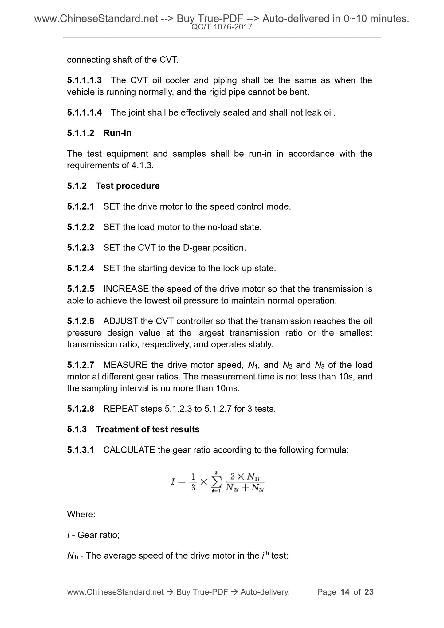
5.1.3.1 CALCULATE the gear ratio according to the following formula:
Where:
I - Gear ratio;
N1i - The average speed of the drive motor in the ith test;
During the test, the difference between the theoretical speed and the actual
speed of the transmission load motor shall not exceed 5%, and the input
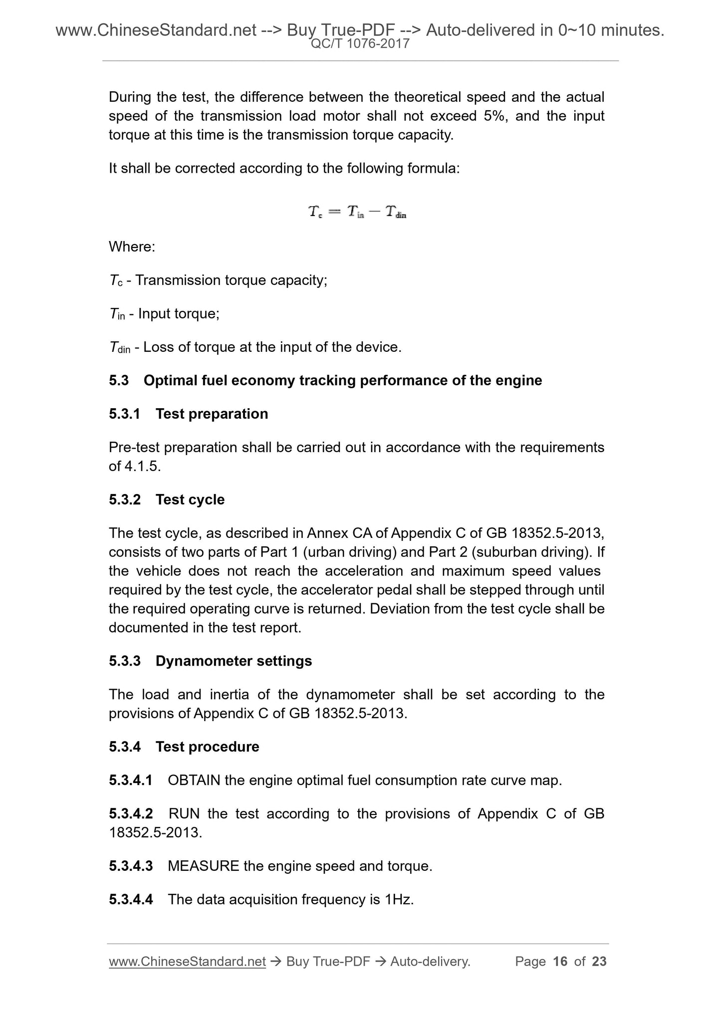
torque at this time is the transmission torque capacity.
It shall be corrected according to the following formula:
Where:
Tc - Transmission torque capacity;
Tin - Input torque;
Tdin - Loss of torque at the input of the device.
5.3 Optimal fuel economy tracking performance of the engine
5.3.1 Test preparation
Pre-test preparation shall be carried out in accordance with the requirements
of 4.1.5.
5.3.2 Test cycle
The test cycle, as described in Annex CA of Appendix C of GB 18352.5-2013,
consists of two parts of Part 1 (urban driving) and Part 2 (suburban driving). If
the vehicle does not reach the acceleration and maximum speed values
required by the test cycle, the accelerator pedal shall be stepped through until
the required operating curve is returned. Deviation from the test cycle shall be
documented in the test report.
5.3.3 Dynamometer settings
The load and inertia of the dynamometer shall be set according to the
provisions of Appendix C of GB 18352.5-2013.
5.3.4 Test procedure
5.3.4.1 OBTAIN the engine optimal fuel consumption rate curve map.
5.3.4.2 RUN the test according to the provisions of Appendix C of GB
18352.5-2013.
5.3.4.3 MEASURE the engine speed and torque.
5.3.4.4 The data acquisition frequency is 1Hz.
Where:
L - Lock-up ratio;
tlock - Lock-up duration;
t - Total duration of the test (excluding the idle time).
5.5 Transmission efficiency
5.5.1 Test preparation
Pre-test preparation shall be carried out in accordance with the requirements
of 5.1.1.
5.5.2 Test procedure
5.5.2.1 SET the drive motor to the speed control mode.
5.5.2.2 SET the load motor to the torque control mode.
5.5.2.3 SET the CVT to the D-gear position.
5.5.2.4 SET the starting device to the lock-up state.
5.5.2.5 SET the drive motor speed to 1,000r/min.
5.5.2.6 ADJUST the CVT controller so that the transmission reaches the oil
pressure design value at the largest transmission ratio, and operates stably.
5.5.2.7 ADJUST the torque of the drive motor to 25%, 50%, and 75% of the
rated torque load, respectively, and MEASURE the torque of the load motor;
after the value is stable, the measurement time is not less than 10s.
5.5.2.8 The load motor speed is increased by an increment of 1,000r/min
(the maximum speed does not exceed the speed corresponding to the vehicle
speed of 120km/h). MAINTAIN the gear ratio and the drive motor torque
unch...
Get QUOTATION in 1-minute: Click QC/T 1076-2017
Historical versions: QC/T 1076-2017
Preview True-PDF (Reload/Scroll if blank)
QC/T 1076-2017: Performance requirements and testing methods for continuously variable transmission
QC/T 1076-2017
AUTOMOTIVE INDUSTRY STANDARD
OF THE PEOPLE’S REPUBLIC OF CHINA
ICS 43.040.50
T 21
Performance requirements and testing methods for
continuously variable transmission
ISSUED ON: APRIL 12, 2017
IMPLEMENTED ON: OCTOBER 1, 2017
Issued by: Ministry of Industry and Information Technology of the
People’s Republic of China.
Table of Contents
Foreword ... 7
1 Scope ... 8
2 Normative references ... 8
3 Terms and definitions ... 9
4 Testing requirements and performance requirements ... 10
5 Testing methods ... 13
Performance requirements and testing methods for
continuously variable transmission
1 Scope
This Standard specifies the performance requirements and testing methods
for continuously variable transmissions (CVTs) for M1 vehicles.
This Standard applies to the M1 vehicles equipped with CVTs, while N1
vehicles equipped with CVTs and M2 vehicles under 3,500kg may be
implemented in accordance with this Standard.
2 Normative references
The following documents are essential for the application of this Standard.
For dated references, only the dated editions apply to this Standard. For
undated references, the latest editions (including all amendments) apply to
this Standard.
GB 15089 Classification of power-driven vehicle and trailers
GB 18352.5-2013 Limits and measurement methods for emissions from
light-duty vehicles (CHINA 5)
GB 19233 Measurement methods of fuel consumption for light-duty
vehicles
QC/T 465 Automotive mechanical transmission terminology and definition
ECE R10 Rev. 3 Uniform provisions concerning the approval of: vehicles
with regard to electromagnetic compatibility
ISO 11451-2 Road vehicles - Vehicle test methods for electrical
disturbances from narrowband radiated electromagnetic energy - Part 2:
Off-vehicle radiation sources
ISO 11452-4 Road vehicles - Vehicle test methods for electrical
disturbances from narrowband radiated electromagnetic energy - Part 4:
Bulk current injection (BCI)
3.11 Starting device
A device that is coupled between the engine and the transmission to transfer
engine torque to the transmission, such as a torque converter, a friction clutch,
etc.
3.12 Lock up
A connection state where the speed difference between input and output of
the starting device is 0.
3.13 Optimal fuel consumption curve
A curve connecting the lowest effective fuel consumption rate under different
operating conditions of the engine.
4 Testing requirements and performance
requirements
4.1 Testing requirements
4.1.1 Testing conditions
4.1.1.1 Environment
During the test, the temperature in the test chamber shall be 288K to 308K
(15°C to 35°C), the relative humidity shall be 20% to 60%, and the altitude
shall not exceed 1,000m.
4.1.1.2 Transmission oil
The transmission oil specified by the transmission manufacturer may be used,
and the fuel quantity is allowed to be adjusted in a manner specified by the
manufacturer.
4.1.1.3 Bench test run-in
Before performing the measurement test of the actual gear ratio and gear
ratio spread, transmission torque capacity, and steady-state efficiency, the
test samples shall be run-in according to the following specifications:
a) The speed of the drive motor is set to 1,000r/min to 2,000r/min, and the
torque is set to 50% of the rated torque.
b) RUN-IN 1h in the states of the largest transmission ratio, the smallest
transmission ratio, and the middle transmission ratio, respectively.
connecting shaft of the CVT.
5.1.1.1.3 The CVT oil cooler and piping shall be the same as when the
vehicle is running normally, and the rigid pipe cannot be bent.
5.1.1.1.4 The joint shall be effectively sealed and shall not leak oil.
5.1.1.2 Run-in
The test equipment and samples shall be run-in in accordance with the
requirements of 4.1.3.
5.1.2 Test procedure
5.1.2.1 SET the drive motor to the speed control mode.
5.1.2.2 SET the load motor to the no-load state.
5.1.2.3 SET the CVT to the D-gear position.
5.1.2.4 SET the starting device to the lock-up state.
5.1.2.5 INCREASE the speed of the drive motor so that the transmission is
able to achieve the lowest oil pressure to maintain normal operation.
5.1.2.6 ADJUST the CVT controller so that the transmission reaches the oil
pressure design value at the largest transmission ratio or the smallest
transmission ratio, respectively, and operates stably.
5.1.2.7 MEASURE the drive motor speed, N1, and N2 and N3 of the load
motor at different gear ratios. The measurement time is not less than 10s, and
the sampling interval is no more than 10ms.
5.1.2.8 REPEAT steps 5.1.2.3 to 5.1.2.7 for 3 tests.
5.1.3 Treatment of test results
5.1.3.1 CALCULATE the gear ratio according to the following formula:
Where:
I - Gear ratio;
N1i - The average speed of the drive motor in the ith test;
During the test, the difference between the theoretical speed and the actual
speed of the transmission load motor shall not exceed 5%, and the input
torque at this time is the transmission torque capacity.
It shall be corrected according to the following formula:
Where:
Tc - Transmission torque capacity;
Tin - Input torque;
Tdin - Loss of torque at the input of the device.
5.3 Optimal fuel economy tracking performance of the engine
5.3.1 Test preparation
Pre-test preparation shall be carried out in accordance with the requirements
of 4.1.5.
5.3.2 Test cycle
The test cycle, as described in Annex CA of Appendix C of GB 18352.5-2013,
consists of two parts of Part 1 (urban driving) and Part 2 (suburban driving). If
the vehicle does not reach the acceleration and maximum speed values
required by the test cycle, the accelerator pedal shall be stepped through until
the required operating curve is returned. Deviation from the test cycle shall be
documented in the test report.
5.3.3 Dynamometer settings
The load and inertia of the dynamometer shall be set according to the
provisions of Appendix C of GB 18352.5-2013.
5.3.4 Test procedure
5.3.4.1 OBTAIN the engine optimal fuel consumption rate curve map.
5.3.4.2 RUN the test according to the provisions of Appendix C of GB
18352.5-2013.
5.3.4.3 MEASURE the engine speed and torque.
5.3.4.4 The data acquisition frequency is 1Hz.
Where:
L - Lock-up ratio;
tlock - Lock-up duration;
t - Total duration of the test (excluding the idle time).
5.5 Transmission efficiency
5.5.1 Test preparation
Pre-test preparation shall be carried out in accordance with the requirements
of 5.1.1.
5.5.2 Test procedure
5.5.2.1 SET the drive motor to the speed control mode.
5.5.2.2 SET the load motor to the torque control mode.
5.5.2.3 SET the CVT to the D-gear position.
5.5.2.4 SET the starting device to the lock-up state.
5.5.2.5 SET the drive motor speed to 1,000r/min.
5.5.2.6 ADJUST the CVT controller so that the transmission reaches the oil
pressure design value at the largest transmission ratio, and operates stably.
5.5.2.7 ADJUST the torque of the drive motor to 25%, 50%, and 75% of the
rated torque load, respectively, and MEASURE the torque of the load motor;
after the value is stable, the measurement time is not less than 10s.
5.5.2.8 The load motor speed is increased by an increment of 1,000r/min
(the maximum speed does not exceed the speed corresponding to the vehicle
speed of 120km/h). MAINTAIN the gear ratio and the drive motor torque
unch...
Share