1
/
of
11
PayPal, credit cards. Download editable-PDF & invoice in 1 second!
TB/T 1632.1-2014 English PDF (TBT1632.1-2014)
TB/T 1632.1-2014 English PDF (TBT1632.1-2014)
Regular price
$400.00 USD
Regular price
Sale price
$400.00 USD
Unit price
/
per
Shipping calculated at checkout.
Couldn't load pickup availability
Delivery: 3 seconds. Download true-PDF + Invoice.
Get QUOTATION in 1-minute: Click TB/T 1632.1-2014
Historical versions: TB/T 1632.1-2014
Preview True-PDF (Reload/Scroll if blank)
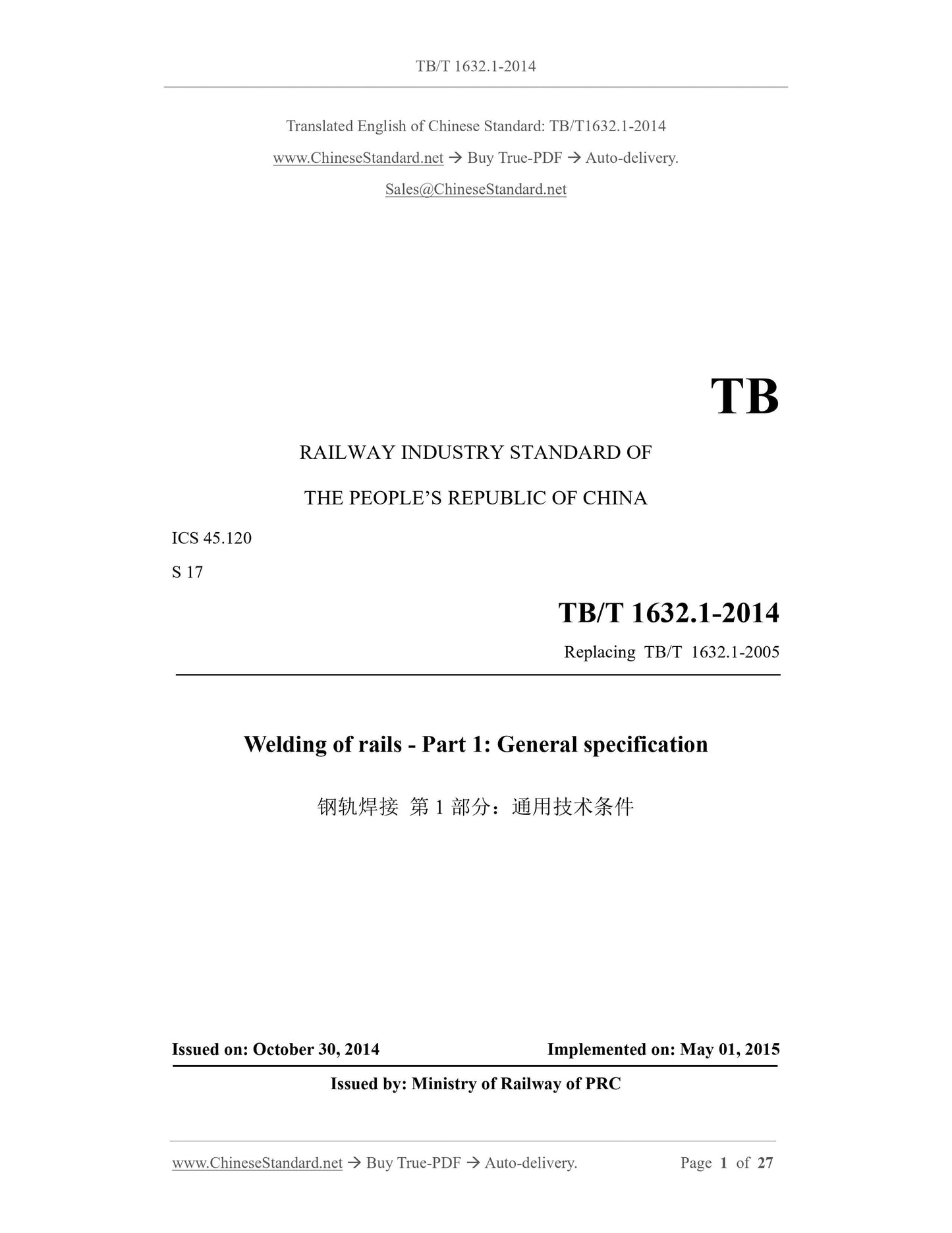
TB/T 1632.1-2014: Welding of rails Part 1: General
TB/T 1632.1-2014
TB
RAILWAY INDUSTRY STANDARD OF
THE PEOPLE’S REPUBLIC OF CHINA
ICS 45.120
S 17
Replacing TB/T 1632.1-2005
Welding of rails - Part 1: General specification
ISSUED ON: OCTOBER 30, 2014
IMPLEMENTED ON: MAY 01, 2015
Issued by: Ministry of Railway of PRC
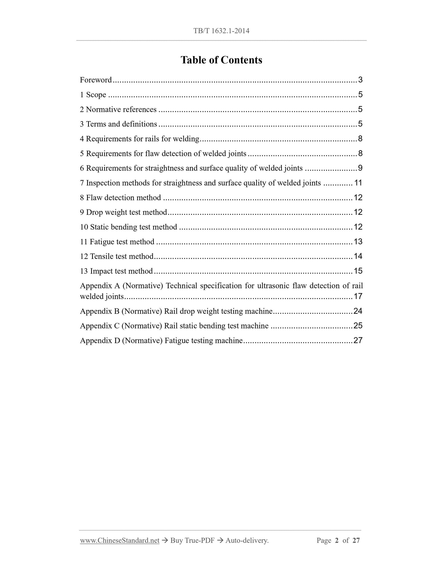
Table of Contents
Foreword ... 3
1 Scope ... 5
2 Normative references ... 5
3 Terms and definitions ... 5
4 Requirements for rails for welding ... 8
5 Requirements for flaw detection of welded joints ... 8
6 Requirements for straightness and surface quality of welded joints ... 9
7 Inspection methods for straightness and surface quality of welded joints ... 11
8 Flaw detection method ... 12
9 Drop weight test method ... 12
10 Static bending test method ... 12
11 Fatigue test method ... 13
12 Tensile test method ... 14
13 Impact test method ... 15
Appendix A (Normative) Technical specification for ultrasonic flaw detection of rail
welded joints ... 17
Appendix B (Normative) Rail drop weight testing machine ... 24
Appendix C (Normative) Rail static bending test machine ... 25
Appendix D (Normative) Fatigue testing machine ... 27
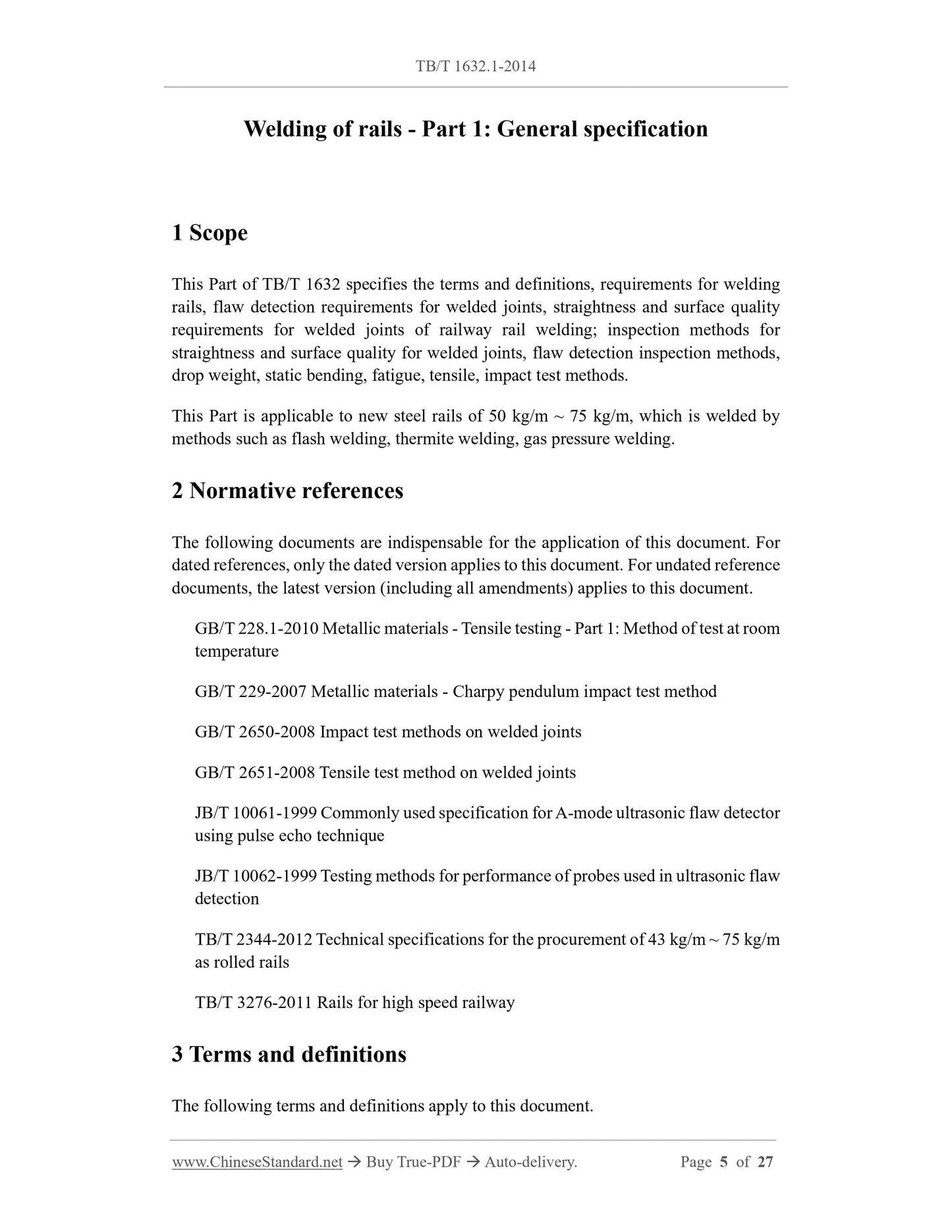
Welding of rails - Part 1: General specification
1 Scope
This Part of TB/T 1632 specifies the terms and definitions, requirements for welding
rails, flaw detection requirements for welded joints, straightness and surface quality
requirements for welded joints of railway rail welding; inspection methods for
straightness and surface quality for welded joints, flaw detection inspection methods,
drop weight, static bending, fatigue, tensile, impact test methods.
This Part is applicable to new steel rails of 50 kg/m ~ 75 kg/m, which is welded by
methods such as flash welding, thermite welding, gas pressure welding.
2 Normative references
The following documents are indispensable for the application of this document. For
dated references, only the dated version applies to this document. For undated reference
documents, the latest version (including all amendments) applies to this document.
GB/T 228.1-2010 Metallic materials - Tensile testing - Part 1: Method of test at room
temperature
GB/T 229-2007 Metallic materials - Charpy pendulum impact test method
GB/T 2650-2008 Impact test methods on welded joints
GB/T 2651-2008 Tensile test method on welded joints
JB/T 10061-1999 Commonly used specification for A-mode ultrasonic flaw detector
using pulse echo technique
JB/T 10062-1999 Testing methods for performance of probes used in ultrasonic flaw
detection
TB/T 2344-2012 Technical specifications for the procurement of 43 kg/m ~ 75 kg/m
as rolled rails
TB/T 3276-2011 Rails for high speed railway
3 Terms and definitions
The following terms and definitions apply to this document.
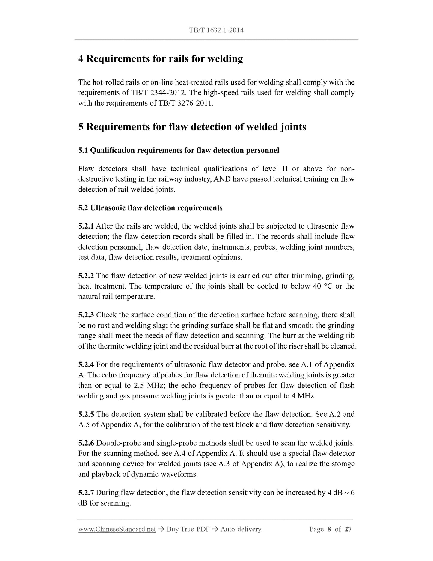
4 Requirements for rails for welding
The hot-rolled rails or on-line heat-treated rails used for welding shall comply with the
requirements of TB/T 2344-2012. The high-speed rails used for welding shall comply
with the requirements of TB/T 3276-2011.
5 Requirements for flaw detection of welded joints
5.1 Qualification requirements for flaw detection personnel
Flaw detectors shall have technical qualifications of level II or above for non-
destructive testing in the railway industry, AND have passed technical training on flaw
detection of rail welded joints.
5.2 Ultrasonic flaw detection requirements
5.2.1 After the rails are welded, the welded joints shall be subjected to ultrasonic flaw
detection; the flaw detection records shall be filled in. The records shall include flaw
detection personnel, flaw detection date, instruments, probes, welding joint numbers,
test data, flaw detection results, treatment opinions.
5.2.2 The flaw detection of new welded joints is carried out after trimming, grinding,
heat treatment. The temperature of the joints shall be cooled to below 40 °C or the
natural rail temperature.
5.2.3 Check the surface condition of the detection surface before scanning, there shall
be no rust and welding slag; the grinding surface shall be flat and smooth; the grinding
range shall meet the needs of flaw detection and scanning. The burr at the welding rib
of the thermite welding joint and the residual burr at the root of the riser shall be cleaned.
5.2.4 For the requirements of ultrasonic flaw detector and probe, see A.1 of Appendix
A. The echo frequency of probes for flaw detection of thermite welding joints is greater
than or equal to 2.5 MHz; the echo frequency of probes for flaw detection of flash
welding and gas pressure welding joints is greater than or equal to 4 MHz.
5.2.5 The detection system shall be calibrated before the flaw detection. See A.2 and
A.5 of Appendix A, for the calibration of the test block and flaw detection sensitivity.
5.2.6 Double-probe and single-probe methods shall be used to scan the welded joints.
For the scanning method, see A.4 of Appendix A. It should use a special flaw detector
and scanning device for welded joints (see A.3 of Appendix A), to realize the storage
and playback of dynamic waveforms.
5.2.7 During flaw detection, the flaw detection sensitivity can be increased by 4 dB ~ 6
dB for scanning.
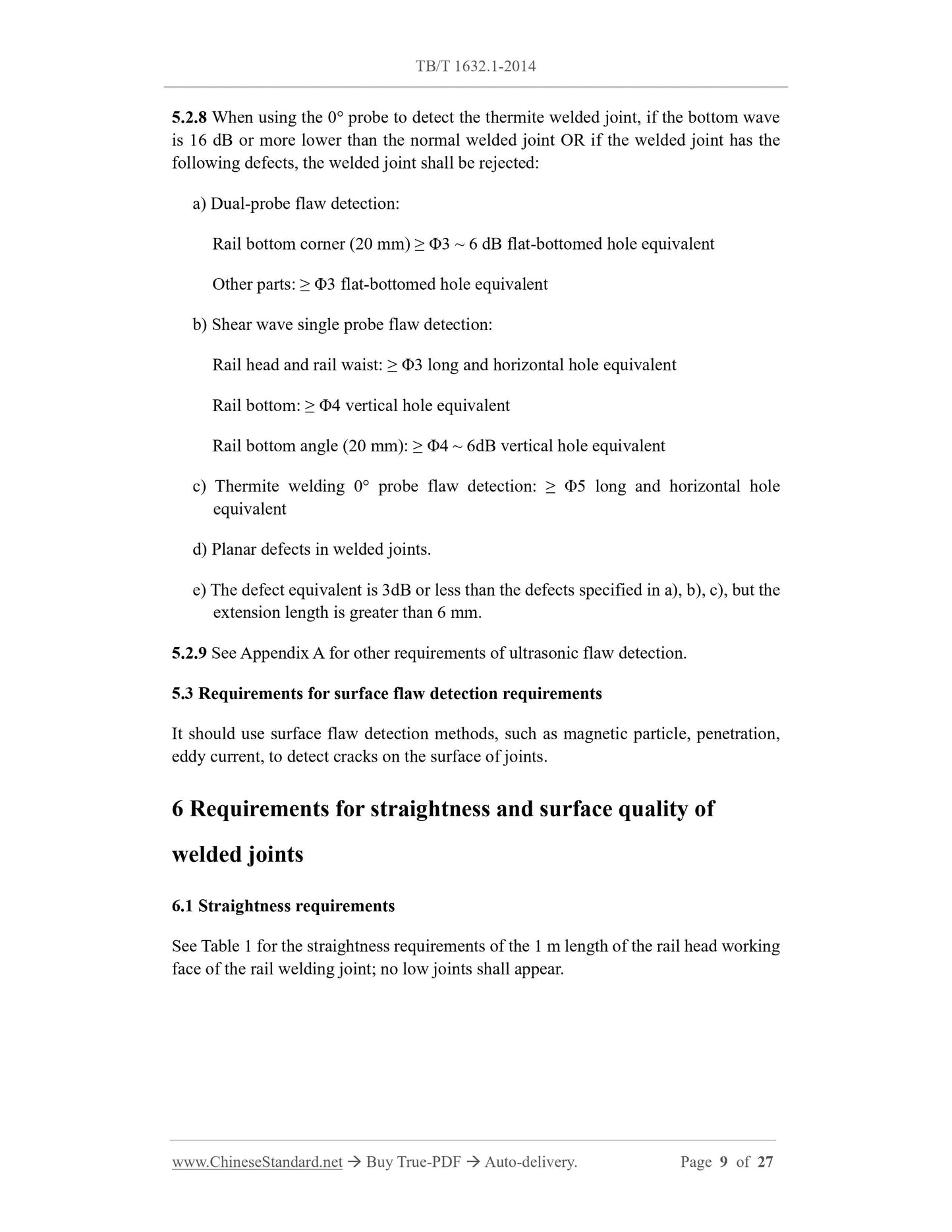
5.2.8 When using the 0° probe to detect the thermite welded joint, if the bottom wave
is 16 dB or more lower than the normal welded joint OR if the welded joint has the
following defects, the welded joint shall be rejected:
a) Dual-probe flaw detection:
Rail bottom corner (20 mm) ≥ Φ3 ~ 6 dB flat-bottomed hole equivalent
Other parts: ≥ Φ3 flat-bottomed hole equivalent
b) Shear wave single probe flaw detection:
Rail head and rail waist: ≥ Φ3 long and horizontal hole equivalent
Rail bottom: ≥ Φ4 vertical hole equivalent
Rail bottom angle (20 mm): ≥ Φ4 ~ 6dB vertical hole equivalent
c) Thermite welding 0° probe flaw detection: ≥ Φ5 long and horizontal hole
equivalent
d) Planar defects in welded joints.
e) The defect equivalent is 3dB or less than the defects specified in a), b), c), but the
extension length is greater than 6 mm.
5.2.9 See Appendix A for other requirements of ultrasonic flaw detection.
5.3 Requirements for surface flaw detection requirements
It should use surface flaw detection methods, such as magnetic particle, penetration,
eddy current, to detect cracks on the surface of joints.
6 Requirements for straightness and surface quality of
welded joints
6.1 Straightness requirements
See Table 1 for the straightness requirements of the 1 m length of the rail head working
face of the rail welding joint; no low joints shall appear.
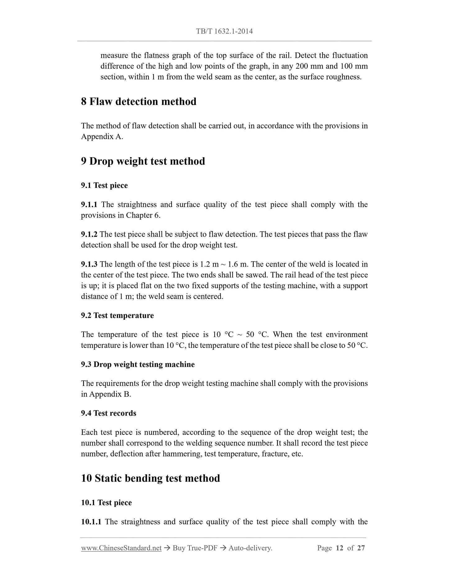
measure the flatness graph of the top surface of the rail. Detect the fluctuation
difference of the high and low points of the graph, in any 200 mm and 100 mm
section, within 1 m from the weld seam as the center, as the surface roughness.
8 Flaw detection method
The method of flaw detection shall be carried out, in accordance with the provisions in
Appendix A.
9 Drop weight test method
9.1 Test piece
9.1.1 The straightness and surface quality of the test piece shall comply with the
provisions in Chapter 6.
9.1.2 The test piece shall be subject to flaw detection. The test pieces that pass the flaw
detection shall be used for the drop weight test.
9.1.3 The length of the test piece is 1.2 m ~ 1.6 m. The center of the weld is located in
the center of the test piece. The two ends shall be sawed. The rail head of the test piece
is up; it is placed flat on the two fixed supports of the testing machin...
Share
