1
/
of
12
www.ChineseStandard.us -- Field Test Asia Pte. Ltd.
GB/T 20042.6-2024 English PDF (GB/T20042.6-2024)
GB/T 20042.6-2024 English PDF (GB/T20042.6-2024)
Regular price
$550.00
Regular price
Sale price
$550.00
Unit price
/
per
Shipping calculated at checkout.
Couldn't load pickup availability
GB/T 20042.6-2024: Proton exchange membrane fuel cell - Part 6: Test method of bipolar plate properties
Delivery: 9 seconds. Download (& Email) true-PDF + Invoice.
Get Quotation: Click GB/T 20042.6-2024 (Self-service in 1-minute)
Historical versions (Master-website): GB/T 20042.6-2024
Preview True-PDF (Reload/Scroll-down if blank)
GB/T 20042.6-2024
GB
NATIONAL STANDARD OF THE
PEOPLE’S REPUBLIC OF CHINA
ICS 27.070
CCS K 82
Replacing GB/T 20042.6-2011
Proton Exchange Membrane Fuel Cell – Part 6.Test Method
of Bipolar Plate Properties
ISSUED ON. MARCH 15, 2024
IMPLEMENTED ON. OCTOBER 1, 2024
Issued by. State Administration for Market Regulation;
Standardization Administration of the People’s Republic of China.
Table of Contents
Foreword... 3
Introduction... 6
1 Scope... 7
2 Normative References... 7
3 Terms and Definitions... 8
4 Flexural Strength Test of Bipolar Plate Materials... 9
5 Density Test of Bipolar Plate Materials... 11
6 Resistance Test of Bipolar Plate Material... 12
7 Corrosion Current Density Test of Bipolar Plate Materials... 16
8 Area Utilization Rate Test of Bipolar Plate Component... 20
9 Thickness Uniformity Test of Bipolar Plate Component... 21
10 Groove Depth Uniformity Test of Bipolar Plate Component... 24
11 Flatness Test of Bipolar Plate Components... 26
12 Relative Flatness Test of Bipolar Plate Component... 27
13 Contact Resistance Test of Bipolar Plate Component... 29
14 Air Tightness Test of Bipolar Plate Component... 29
15 Water Contact Angle Test of Bipolar Plate Component... 33
16 Coating Thickness Test of Bipolar Plate Component... 34
17 Coating Bonding Strength Test of Bipolar Plate Component... 35
18 Corrosion Current Density Test of Bipolar Plate Component... 36
19 Specific Heat Capacity Test of Bipolar Plate Component... 37
20 Thermal Conductivity Test of Bipolar Plate Component... 38
21 Precipitation Ion Composition and Concentration Test for Bipolar Plate Component
... 39
22 Applicability of Test Indicators, Test Preparation and Test Report... 41
Appendix A (Normative) Applicability of Test Indicators... 42
Appendix B (Informative) Test Preparation... 43
Appendix C (Informative) Test Report... 44
Bibliography... 47
Proton Exchange Membrane Fuel Cell – Part 6.Test Method
of Bipolar Plate Properties
1 Scope
This Document specifies the test methods for the flexural strength, density, resistance and
corrosion current density, etc. of bipolar plate materials for proton exchange membrane fuel
cells; and the test methods for the area utilization, thickness uniformity, groove depth uniformity,
flatness, relative flatness, contact resistance, air tightness, etc. of bipolar plate components.
This Document is applicable to various types of bipolar plate materials and components for
proton exchange membrane fuel cells.
NOTE. The definitions of bipolar plate materials and bipolar plate components are as follows.
a) Bipolar plate material. Plate material in the same state as the finished bipolar plate material;
b) Bipolar plate component. Finished bipolar plate in the same state as the used state.
2 Normative References
The provisions in following documents become the essential provisions of this Document
through reference in this Document. For the dated documents, only the versions with the dates
indicated are applicable to this Document; for the undated documents, only the latest version
(including all the amendments) is applicable to this Document.
GB/T 230.2 Metallic materials – Rockwell hardness test – Part 2.Verification and
calibration of testing machines and indenters
GB/T 1958 Geometrical product Specifications (GPS) - Geometrical tolerance -
Verification prescription
GB/T 4472-2011 Determination of density and relative density for chemical products
GB/T 13465.2 Test method of impermeable graphite materials - Part 2.Flexure strength
GB/T 19466.4-2016 Plastics - Differential scanning calorimetry (DSC) - Part 4.
Determination of specific heat capacity
GB/T 20042.1-2017 Proton exchange membrane fuel cell - Part 1.Terminology
Take 3 valid samples as a group; calculate the average value as the test result, and retain two
digits after the decimal point.
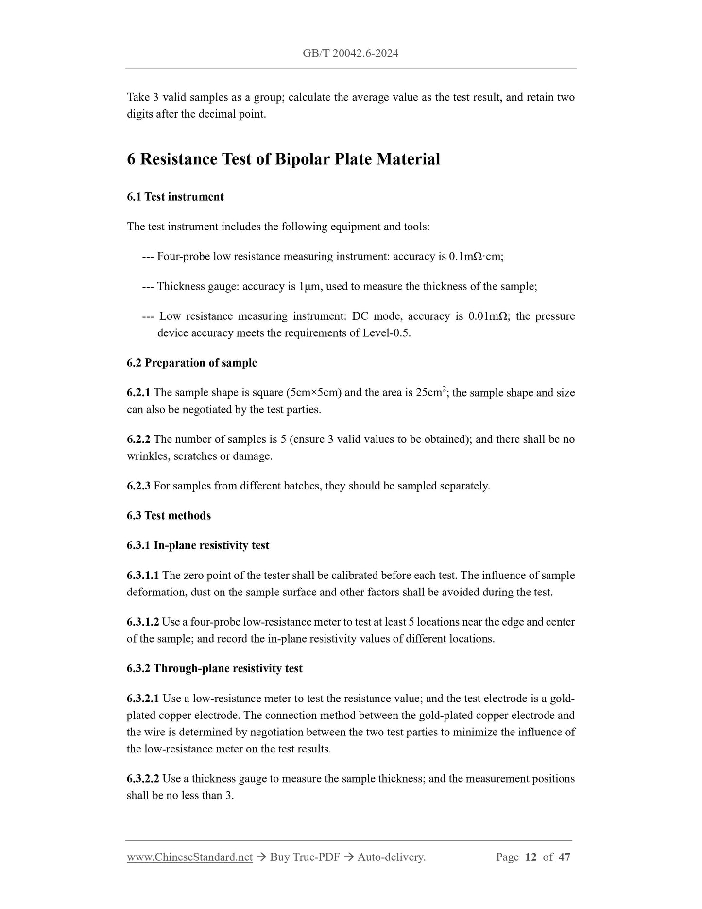
6 Resistance Test of Bipolar Plate Material
6.1 Test instrument
The test instrument includes the following equipment and tools.
--- Four-probe low resistance measuring instrument. accuracy is 0.1mΩ·cm;
--- Thickness gauge. accuracy is 1μm, used to measure the thickness of the sample;
--- Low resistance measuring instrument. DC mode, accuracy is 0.01mΩ; the pressure
device accuracy meets the requirements of Level-0.5.
6.2 Preparation of sample
6.2.1 The sample shape is square (5cm×5cm) and the area is 25cm2; the sample shape and size
can also be negotiated by the test parties.
6.2.2 The number of samples is 5 (ensure 3 valid values to be obtained); and there shall be no
wrinkles, scratches or damage.
6.2.3 For samples from different batches, they should be sampled separately.
6.3 Test methods
6.3.1 In-plane resistivity test
6.3.1.1 The zero point of the tester shall be calibrated before each test. The influence of sample
deformation, dust on the sample surface and other factors shall be avoided during the test.
6.3.1.2 Use a four-probe low-resistance meter to test at least 5 locations near the edge and center
of the sample; and record the in-plane resistivity values of different locations.
6.3.2 Through-plane resistivity test
6.3.2.1 Use a low-resistance meter to test the resistance value; and the test electrode is a gold-
plated copper electrode. The connection method between the gold-plated copper electrode and
the wire is determined by negotiation between the two test parties to minimize the influence of
the low-resistance meter on the test results.
6.3.2.2 Use a thickness gauge to measure the sample thickness; and the measurement positions
shall be no less than 3.
6.3.2.3 Install the sample on the test device as shown in Figure 1.During the test, place
5cm×5cm carbon paper on both sides of the sample as a support to further improve the contact
condition. During the test, record a resistance value for every 0.1MPa increase in pressure until
the change rate of the current resistance test value relative to the previous resistance test value
is ≤5%, then it is considered that the minimum resistance value has been reached and the test
is stopped. The resistance value under different pressures is recorded as Rm.
6.3.2.4 Use new carbon paper of the same specification for each test, and the carbon paper
manufacturer and model shall be indicated in the test report.
NOTE. The test current density is 40mA/cm2 or determined by negotiation between the two test parties.
The test pressure range is generally 0.1MPa~2.0MPa; and the resistance value at a pressure of 1.5MPa
is selected, or it is determined by negotiation between the two test parties.
6.3.3 Contact resistance test
6.3.3.1 Use a low resistance meter to test the resistance value; and the test electrode is a gold-
plated copper electrode. The connection method between the gold-plated copper electrode and
the wire is determined by negotiation between the two test parties to minimize the impact of
the low resistance meter on the test results.
6.3.3.2 Install the sample on the test device as shown in Figure 1.During the test, place
5cm×5cm carbon paper on both sides of the sample as a support to further improve the contact
condition. During the test, record a resistance value for each 0.1MPa increase in pressure until
the change rate of the current resistance test value relative to the previous resistance test value
is ≤5%; then it is considered that the minimum resistance value is reached and the test is stopped.
The resistance value under different pressures is recorded as R1.
6.3.3.3 In the same way, place a 5cm×5cm carbon paper between the two gold-plated copper
electrodes; test according to the method described in 6.3.3.2; and record the resistance value R2
under different pressures.
6.3.3.4 Use new carbon paper of the same specification for each test; and the carbon paper
manufacturer and model shall be indicated in the test report.
NOTE. The test current density is 40mA/cm2, or determined by negotiation between the two test parties.
The test pressure range is generally 0.1 MPa~2.0 MPa; and the resistance value at a pressure of 1.5MPa
is selected, or determined by negotiation between the two test parties.
NOTE. The thickness of the samples for the two tests satisfies. ̅1=(1.5~2.0)̅2, or is determined by
negotiation between the two test parties.
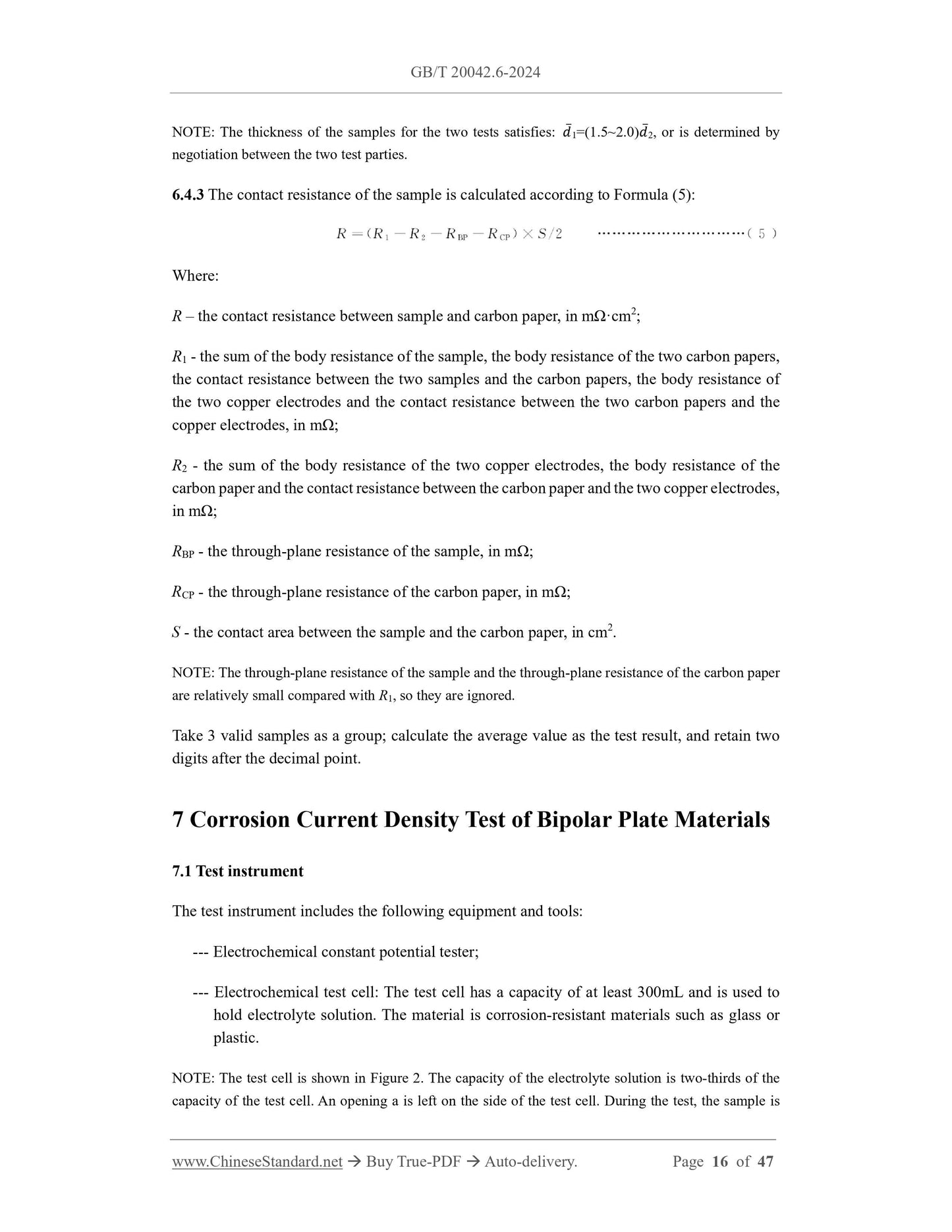
6.4.3 The contact resistance of the sample is calculated according to Formula (5).
Where.
R – the contact resistance between sample and carbon paper, in mΩ·cm2;
R1 - the sum of the body resistance of the sample, the body resistance of the two carbon papers,
the contact resistance between the two samples and the carbon papers, the body resistance of
the two copper electrodes and the contact resistance between the two carbon papers and the
copper electrodes, in mΩ;
R2 - the sum of the body resistance of the two copper electrodes, the body resistance of the
carbon paper and the contact resistance between the carbon paper and the two copper electrodes,
in mΩ;
RBP - the through-plane resistance of the sample, in mΩ;
RCP - the through-plane resistance of the carbon paper, in mΩ;
S - the contact area between the sample and the carbon paper, in cm2.
NOTE. The through-plane resistance of the sample and the through-plane resistance of the carbon paper
are relatively small compared with R1, so they are ignored.
Take 3 valid samples as a group; calculate the average value as the test result, and retain two
digits after the decimal point.
7 Corrosion Current Density Test of Bipolar Plate Materials
7.1 Test instrument
The test instrument includes the following equipment and tools.
--- Electrochemical constant potential tester;
--- Electrochemical test cell. The test cell has a capacity of at least 300mL and is used to
hold electrolyte solution. The material is corrosion-resistant materials such as glass or
plastic.
NOTE. The test cell is shown in Figure 2.The capacity of the electrolyte solution is two-thirds of the
capacity of the test cell. An opening a is left on the side of the test cell. During the test, the sample is
c - installation port of inlet pipe;
d - installation port of outlet pipe;
e - installation port of auxiliary electrode;
f - installation port of solution replacement and temperature control device.
Figure 2 -- Schematic diagram of the test cell
7.2 Preparation of sample
7.2.1 Cut the test material of a certain size as the sample, and ensure that the effective area of
the sample is at least 1cm2.
7.2.2 Clean the sample surface with ethanol or other solvents; and dry it in a nitrogen
environment at 80℃ for 10min.
7.2.3 Seal the sample according to the opening shape on the side of the electrolytic cell to ensure
that there is no leakage during the test.
7.2.4 The number of samples is 5 (ensure 3 valid values to be obtained); and there shall be no
wrinkles, scratches or damage.
7.2.5 For samples from different batches, they should be sampled separately.
7.3 Test methods
7.3.1 Open circuit potential test
7.3.1.1 The sample is used as the working electrode; the saturated calomel electrode is used as
the reference electrode; and the platinum sheet or platinum mesh is used as the auxiliary
electrode for testing. The reference electrode type can also be determined by negotiation
between the two test parties.
7.3.1.2 Air or hydrogen is introduced into the H2SO4 electrolyte solution with a temperature of
80℃, a F- content of 0.1mg/L, and a pH of 3 at a flow rate of 20mL/min. After ventilation for
15min, the system can be stabilized and the test can be started.
NOTE. Use NaF, KF or HF containing F solution. The operation of related chemicals shall be carried out
in accordance with the requirements of the Regulations on the Safety Management of Hazardous
Chemicals. The requirements for F- below are the same as these requirements.
7.3.1.3 Open circuit potential test is carried out in simulated cathode and anode environments
respectively. The test lasts for at least 30min and the potential changes within 2min without
exceeding 5mV can be considered stable and the corrosion current density test can be started
then. This test needs to be performed once before the dynamic potential test and the constant
potential test.
7.3.2 Dynamic potential test
7.3.2.1 Test with the sample as the working electrode, the saturated calomel electrode as the
reference electrode, and the platinum sheet or platinum mesh as the auxiliary electrode. The
reference electrode type can also be determined by negotiation between the two test parties;
and the linear potential scanning range is converted accordingly according to the used reference
electrode type.
7.3.2.2 Air or hydrogen is introduced into the H2SO4 electrolyte solution with a temperature of
80℃, a F- content of 0.1mg/L, and a pH of 3 at a flow rate of 20mL/min to simulate the cathode
or anode environment of the fuel cell. After ventilation for 15 min, the system is stable and the
test can be started.
7.3.2.3 The sample is subjected to a linear potential scan at a scan rate of 2mV/s and a potential
scan range of -0.5V~1.4V (vs. SCE). The test data are recorded separately under different gas
environments.
7.3.2.4 Perform Tafel fitting on the measured linear potential scanning curve. The current
corresponding to the intersection of the Tafel straight line is the corrosion current of the sample.
7.3.3 Constant potential test
7.3.3.1 Test with the sample as the working electrode, the saturated calomel electrode as the
reference electrode, and the platinum sheet or platinum mesh as the auxiliary electrode. The
reference electrode type can also be determined by negotiation between the two test parties;
and the test potential is converted accordingly according to the used reference electrode type.
7.3.3.2 Air or hydrogen is introduced into the H2SO4 electrolyte solution with a temperature of
80℃, a F- content of 0.1mg/L, and a pH of 3 at a flow rate of 20mL/min to simulate the cathode
or anode environment of the fuel cell.
7.3.3.3 Apply 0.6V (vs. SCE) and -0.1V (vs. SCE) potentials to the samples in the simulated
cathode a...
Delivery: 9 seconds. Download (& Email) true-PDF + Invoice.
Get Quotation: Click GB/T 20042.6-2024 (Self-service in 1-minute)
Historical versions (Master-website): GB/T 20042.6-2024
Preview True-PDF (Reload/Scroll-down if blank)
GB/T 20042.6-2024
GB
NATIONAL STANDARD OF THE
PEOPLE’S REPUBLIC OF CHINA
ICS 27.070
CCS K 82
Replacing GB/T 20042.6-2011
Proton Exchange Membrane Fuel Cell – Part 6.Test Method
of Bipolar Plate Properties
ISSUED ON. MARCH 15, 2024
IMPLEMENTED ON. OCTOBER 1, 2024
Issued by. State Administration for Market Regulation;
Standardization Administration of the People’s Republic of China.
Table of Contents
Foreword... 3
Introduction... 6
1 Scope... 7
2 Normative References... 7
3 Terms and Definitions... 8
4 Flexural Strength Test of Bipolar Plate Materials... 9
5 Density Test of Bipolar Plate Materials... 11
6 Resistance Test of Bipolar Plate Material... 12
7 Corrosion Current Density Test of Bipolar Plate Materials... 16
8 Area Utilization Rate Test of Bipolar Plate Component... 20
9 Thickness Uniformity Test of Bipolar Plate Component... 21
10 Groove Depth Uniformity Test of Bipolar Plate Component... 24
11 Flatness Test of Bipolar Plate Components... 26
12 Relative Flatness Test of Bipolar Plate Component... 27
13 Contact Resistance Test of Bipolar Plate Component... 29
14 Air Tightness Test of Bipolar Plate Component... 29
15 Water Contact Angle Test of Bipolar Plate Component... 33
16 Coating Thickness Test of Bipolar Plate Component... 34
17 Coating Bonding Strength Test of Bipolar Plate Component... 35
18 Corrosion Current Density Test of Bipolar Plate Component... 36
19 Specific Heat Capacity Test of Bipolar Plate Component... 37
20 Thermal Conductivity Test of Bipolar Plate Component... 38
21 Precipitation Ion Composition and Concentration Test for Bipolar Plate Component
... 39
22 Applicability of Test Indicators, Test Preparation and Test Report... 41
Appendix A (Normative) Applicability of Test Indicators... 42
Appendix B (Informative) Test Preparation... 43
Appendix C (Informative) Test Report... 44
Bibliography... 47
Proton Exchange Membrane Fuel Cell – Part 6.Test Method
of Bipolar Plate Properties
1 Scope
This Document specifies the test methods for the flexural strength, density, resistance and
corrosion current density, etc. of bipolar plate materials for proton exchange membrane fuel
cells; and the test methods for the area utilization, thickness uniformity, groove depth uniformity,
flatness, relative flatness, contact resistance, air tightness, etc. of bipolar plate components.
This Document is applicable to various types of bipolar plate materials and components for
proton exchange membrane fuel cells.
NOTE. The definitions of bipolar plate materials and bipolar plate components are as follows.
a) Bipolar plate material. Plate material in the same state as the finished bipolar plate material;
b) Bipolar plate component. Finished bipolar plate in the same state as the used state.
2 Normative References
The provisions in following documents become the essential provisions of this Document
through reference in this Document. For the dated documents, only the versions with the dates
indicated are applicable to this Document; for the undated documents, only the latest version
(including all the amendments) is applicable to this Document.
GB/T 230.2 Metallic materials – Rockwell hardness test – Part 2.Verification and
calibration of testing machines and indenters
GB/T 1958 Geometrical product Specifications (GPS) - Geometrical tolerance -
Verification prescription
GB/T 4472-2011 Determination of density and relative density for chemical products
GB/T 13465.2 Test method of impermeable graphite materials - Part 2.Flexure strength
GB/T 19466.4-2016 Plastics - Differential scanning calorimetry (DSC) - Part 4.
Determination of specific heat capacity
GB/T 20042.1-2017 Proton exchange membrane fuel cell - Part 1.Terminology
Take 3 valid samples as a group; calculate the average value as the test result, and retain two
digits after the decimal point.
6 Resistance Test of Bipolar Plate Material
6.1 Test instrument
The test instrument includes the following equipment and tools.
--- Four-probe low resistance measuring instrument. accuracy is 0.1mΩ·cm;
--- Thickness gauge. accuracy is 1μm, used to measure the thickness of the sample;
--- Low resistance measuring instrument. DC mode, accuracy is 0.01mΩ; the pressure
device accuracy meets the requirements of Level-0.5.
6.2 Preparation of sample
6.2.1 The sample shape is square (5cm×5cm) and the area is 25cm2; the sample shape and size
can also be negotiated by the test parties.
6.2.2 The number of samples is 5 (ensure 3 valid values to be obtained); and there shall be no
wrinkles, scratches or damage.
6.2.3 For samples from different batches, they should be sampled separately.
6.3 Test methods
6.3.1 In-plane resistivity test
6.3.1.1 The zero point of the tester shall be calibrated before each test. The influence of sample
deformation, dust on the sample surface and other factors shall be avoided during the test.
6.3.1.2 Use a four-probe low-resistance meter to test at least 5 locations near the edge and center
of the sample; and record the in-plane resistivity values of different locations.
6.3.2 Through-plane resistivity test
6.3.2.1 Use a low-resistance meter to test the resistance value; and the test electrode is a gold-
plated copper electrode. The connection method between the gold-plated copper electrode and
the wire is determined by negotiation between the two test parties to minimize the influence of
the low-resistance meter on the test results.
6.3.2.2 Use a thickness gauge to measure the sample thickness; and the measurement positions
shall be no less than 3.
6.3.2.3 Install the sample on the test device as shown in Figure 1.During the test, place
5cm×5cm carbon paper on both sides of the sample as a support to further improve the contact
condition. During the test, record a resistance value for every 0.1MPa increase in pressure until
the change rate of the current resistance test value relative to the previous resistance test value
is ≤5%, then it is considered that the minimum resistance value has been reached and the test
is stopped. The resistance value under different pressures is recorded as Rm.
6.3.2.4 Use new carbon paper of the same specification for each test, and the carbon paper
manufacturer and model shall be indicated in the test report.
NOTE. The test current density is 40mA/cm2 or determined by negotiation between the two test parties.
The test pressure range is generally 0.1MPa~2.0MPa; and the resistance value at a pressure of 1.5MPa
is selected, or it is determined by negotiation between the two test parties.
6.3.3 Contact resistance test
6.3.3.1 Use a low resistance meter to test the resistance value; and the test electrode is a gold-
plated copper electrode. The connection method between the gold-plated copper electrode and
the wire is determined by negotiation between the two test parties to minimize the impact of
the low resistance meter on the test results.
6.3.3.2 Install the sample on the test device as shown in Figure 1.During the test, place
5cm×5cm carbon paper on both sides of the sample as a support to further improve the contact
condition. During the test, record a resistance value for each 0.1MPa increase in pressure until
the change rate of the current resistance test value relative to the previous resistance test value
is ≤5%; then it is considered that the minimum resistance value is reached and the test is stopped.
The resistance value under different pressures is recorded as R1.
6.3.3.3 In the same way, place a 5cm×5cm carbon paper between the two gold-plated copper
electrodes; test according to the method described in 6.3.3.2; and record the resistance value R2
under different pressures.
6.3.3.4 Use new carbon paper of the same specification for each test; and the carbon paper
manufacturer and model shall be indicated in the test report.
NOTE. The test current density is 40mA/cm2, or determined by negotiation between the two test parties.
The test pressure range is generally 0.1 MPa~2.0 MPa; and the resistance value at a pressure of 1.5MPa
is selected, or determined by negotiation between the two test parties.
NOTE. The thickness of the samples for the two tests satisfies. ̅1=(1.5~2.0)̅2, or is determined by
negotiation between the two test parties.
6.4.3 The contact resistance of the sample is calculated according to Formula (5).
Where.
R – the contact resistance between sample and carbon paper, in mΩ·cm2;
R1 - the sum of the body resistance of the sample, the body resistance of the two carbon papers,
the contact resistance between the two samples and the carbon papers, the body resistance of
the two copper electrodes and the contact resistance between the two carbon papers and the
copper electrodes, in mΩ;
R2 - the sum of the body resistance of the two copper electrodes, the body resistance of the
carbon paper and the contact resistance between the carbon paper and the two copper electrodes,
in mΩ;
RBP - the through-plane resistance of the sample, in mΩ;
RCP - the through-plane resistance of the carbon paper, in mΩ;
S - the contact area between the sample and the carbon paper, in cm2.
NOTE. The through-plane resistance of the sample and the through-plane resistance of the carbon paper
are relatively small compared with R1, so they are ignored.
Take 3 valid samples as a group; calculate the average value as the test result, and retain two
digits after the decimal point.
7 Corrosion Current Density Test of Bipolar Plate Materials
7.1 Test instrument
The test instrument includes the following equipment and tools.
--- Electrochemical constant potential tester;
--- Electrochemical test cell. The test cell has a capacity of at least 300mL and is used to
hold electrolyte solution. The material is corrosion-resistant materials such as glass or
plastic.
NOTE. The test cell is shown in Figure 2.The capacity of the electrolyte solution is two-thirds of the
capacity of the test cell. An opening a is left on the side of the test cell. During the test, the sample is
c - installation port of inlet pipe;
d - installation port of outlet pipe;
e - installation port of auxiliary electrode;
f - installation port of solution replacement and temperature control device.
Figure 2 -- Schematic diagram of the test cell
7.2 Preparation of sample
7.2.1 Cut the test material of a certain size as the sample, and ensure that the effective area of
the sample is at least 1cm2.
7.2.2 Clean the sample surface with ethanol or other solvents; and dry it in a nitrogen
environment at 80℃ for 10min.
7.2.3 Seal the sample according to the opening shape on the side of the electrolytic cell to ensure
that there is no leakage during the test.
7.2.4 The number of samples is 5 (ensure 3 valid values to be obtained); and there shall be no
wrinkles, scratches or damage.
7.2.5 For samples from different batches, they should be sampled separately.
7.3 Test methods
7.3.1 Open circuit potential test
7.3.1.1 The sample is used as the working electrode; the saturated calomel electrode is used as
the reference electrode; and the platinum sheet or platinum mesh is used as the auxiliary
electrode for testing. The reference electrode type can also be determined by negotiation
between the two test parties.
7.3.1.2 Air or hydrogen is introduced into the H2SO4 electrolyte solution with a temperature of
80℃, a F- content of 0.1mg/L, and a pH of 3 at a flow rate of 20mL/min. After ventilation for
15min, the system can be stabilized and the test can be started.
NOTE. Use NaF, KF or HF containing F solution. The operation of related chemicals shall be carried out
in accordance with the requirements of the Regulations on the Safety Management of Hazardous
Chemicals. The requirements for F- below are the same as these requirements.
7.3.1.3 Open circuit potential test is carried out in simulated cathode and anode environments
respectively. The test lasts for at least 30min and the potential changes within 2min without
exceeding 5mV can be considered stable and the corrosion current density test can be started
then. This test needs to be performed once before the dynamic potential test and the constant
potential test.
7.3.2 Dynamic potential test
7.3.2.1 Test with the sample as the working electrode, the saturated calomel electrode as the
reference electrode, and the platinum sheet or platinum mesh as the auxiliary electrode. The
reference electrode type can also be determined by negotiation between the two test parties;
and the linear potential scanning range is converted accordingly according to the used reference
electrode type.
7.3.2.2 Air or hydrogen is introduced into the H2SO4 electrolyte solution with a temperature of
80℃, a F- content of 0.1mg/L, and a pH of 3 at a flow rate of 20mL/min to simulate the cathode
or anode environment of the fuel cell. After ventilation for 15 min, the system is stable and the
test can be started.
7.3.2.3 The sample is subjected to a linear potential scan at a scan rate of 2mV/s and a potential
scan range of -0.5V~1.4V (vs. SCE). The test data are recorded separately under different gas
environments.
7.3.2.4 Perform Tafel fitting on the measured linear potential scanning curve. The current
corresponding to the intersection of the Tafel straight line is the corrosion current of the sample.
7.3.3 Constant potential test
7.3.3.1 Test with the sample as the working electrode, the saturated calomel electrode as the
reference electrode, and the platinum sheet or platinum mesh as the auxiliary electrode. The
reference electrode type can also be determined by negotiation between the two test parties;
and the test potential is converted accordingly according to the used reference electrode type.
7.3.3.2 Air or hydrogen is introduced into the H2SO4 electrolyte solution with a temperature of
80℃, a F- content of 0.1mg/L, and a pH of 3 at a flow rate of 20mL/min to simulate the cathode
or anode environment of the fuel cell.
7.3.3.3 Apply 0.6V (vs. SCE) and -0.1V (vs. SCE) potentials to the samples in the simulated
cathode a...
Share