1
/
of
12
PayPal, credit cards. Download editable-PDF and invoice in 1 second!
CB1146.9-1996 English PDF
CB1146.9-1996 English PDF
Regular price
$140.00 USD
Regular price
Sale price
$140.00 USD
Unit price
/
per
Shipping calculated at checkout.
Couldn't load pickup availability
Delivery: 3 seconds. Download true-PDF + Invoice.
Get Quotation: Click CB1146.9-1996 (Self-service in 1-minute)
Historical versions (Master-website): CB1146.9-1996
Preview True-PDF (Reload/Scroll-down if blank)
CB1146.9-1996:
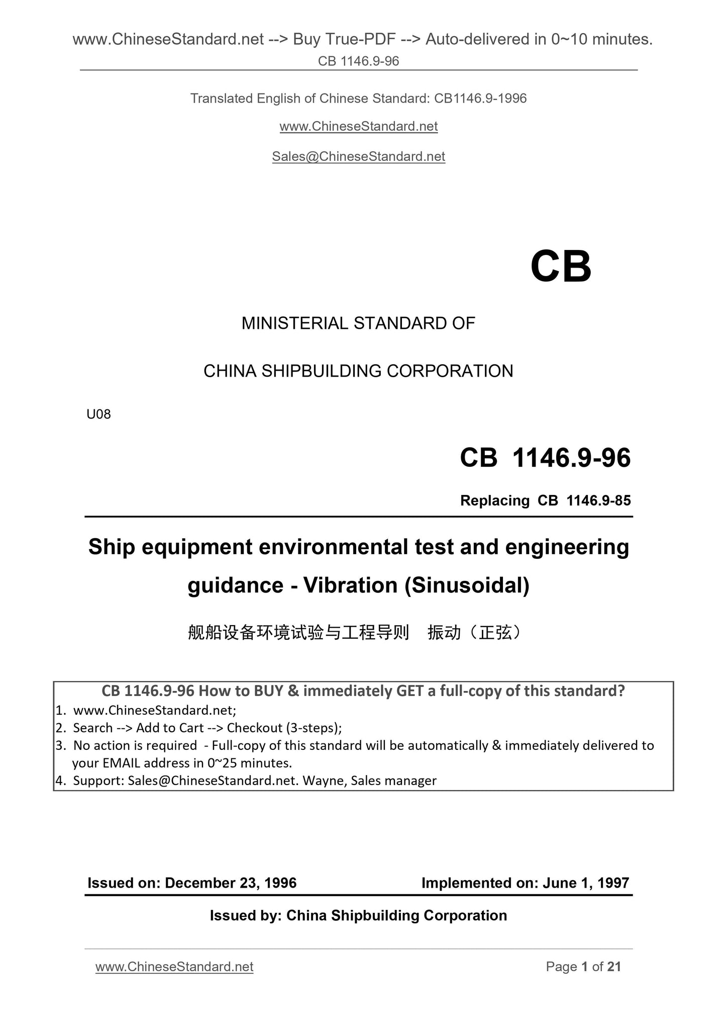
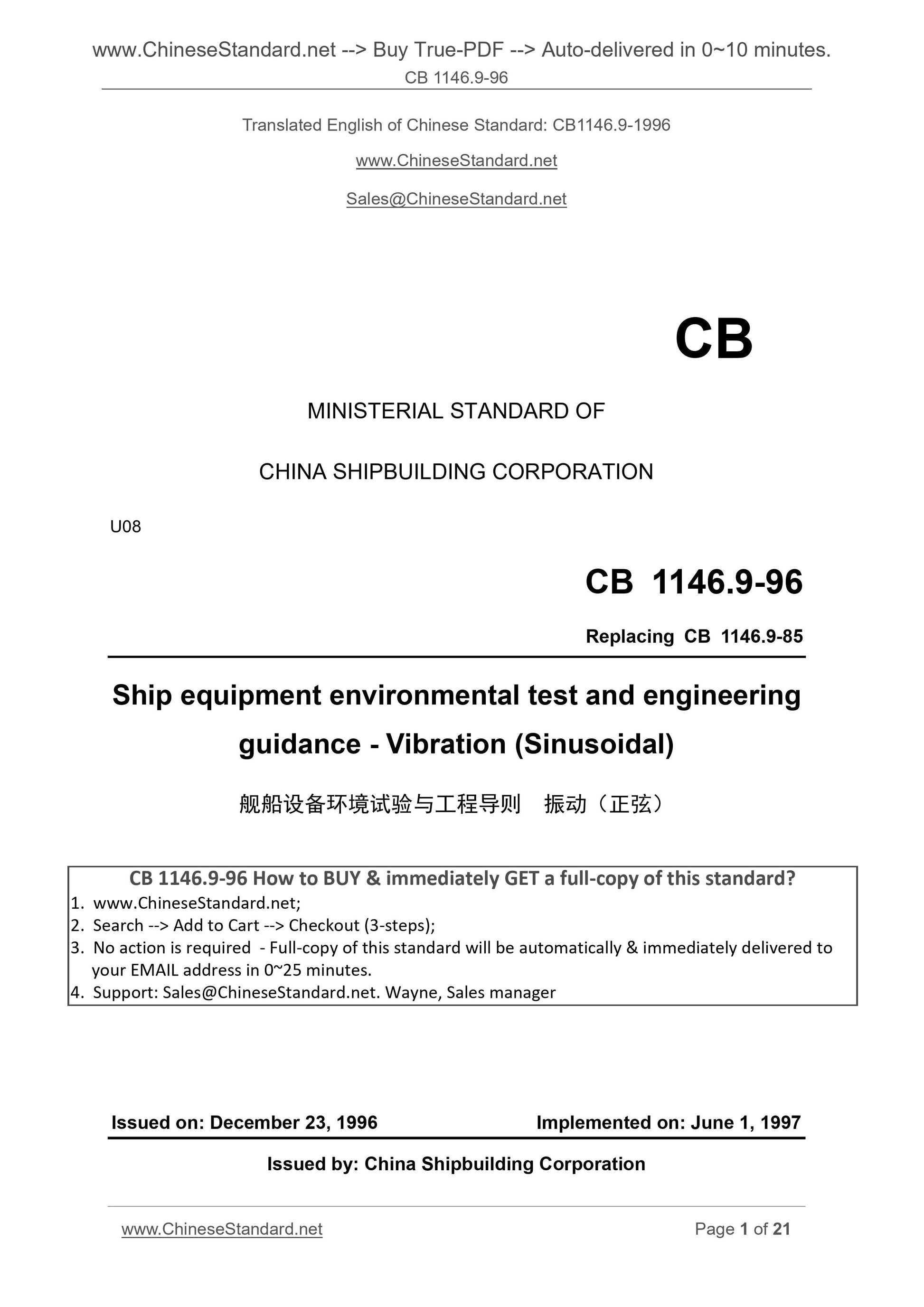
CB 1146.9-96
CB
MINISTERIAL STANDARD OF
CHINA SHIPBUILDING CORPORATION
U08
Replacing CB 1146.9-85
Ship equipment environmental test and engineering
guidance - Vibration (Sinusoidal)
ISSUED ON. DECEMBER 23, 1996
IMPLEMENTED ON. JUNE 1, 1997
Issued by. China Shipbuilding Corporation
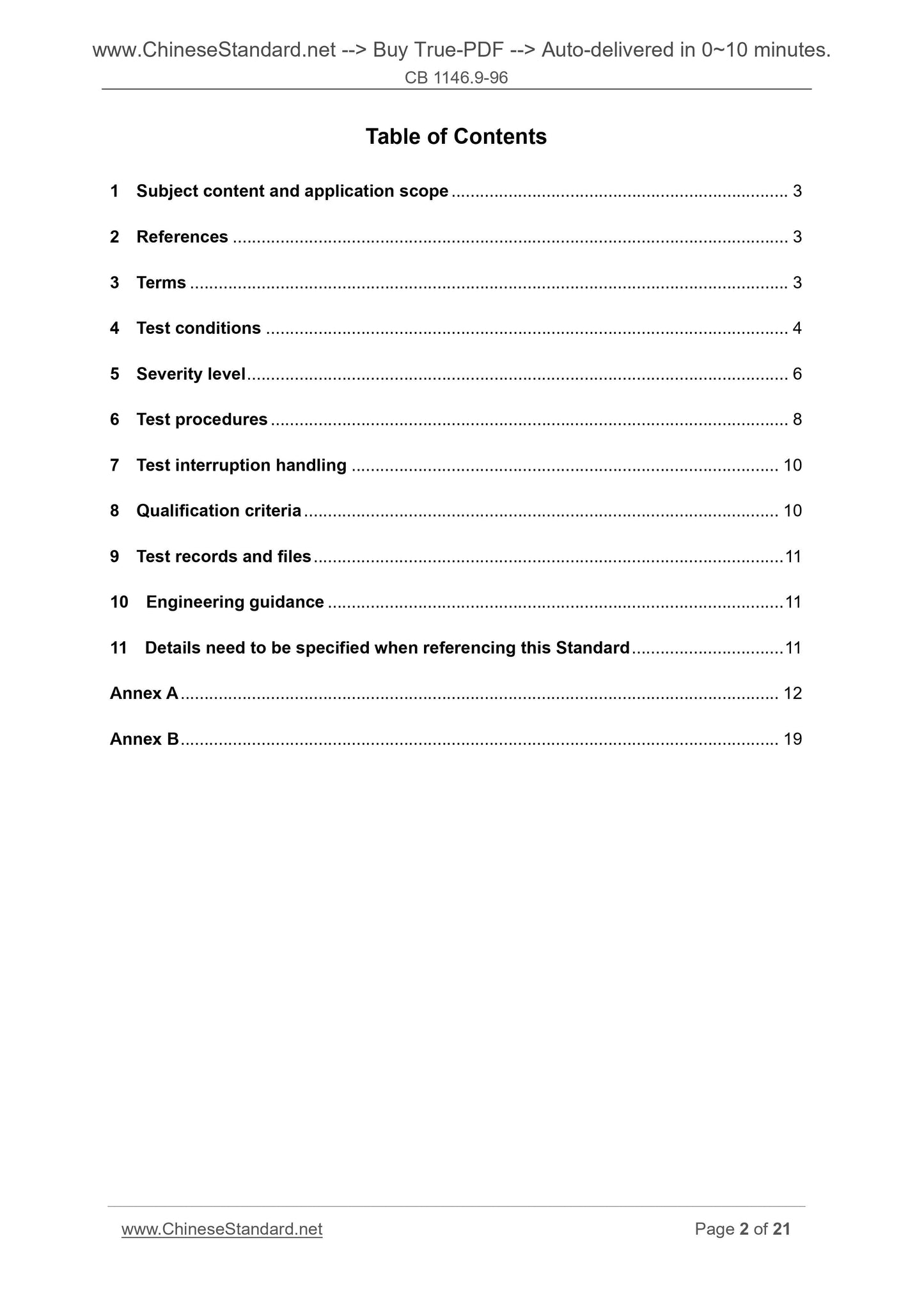
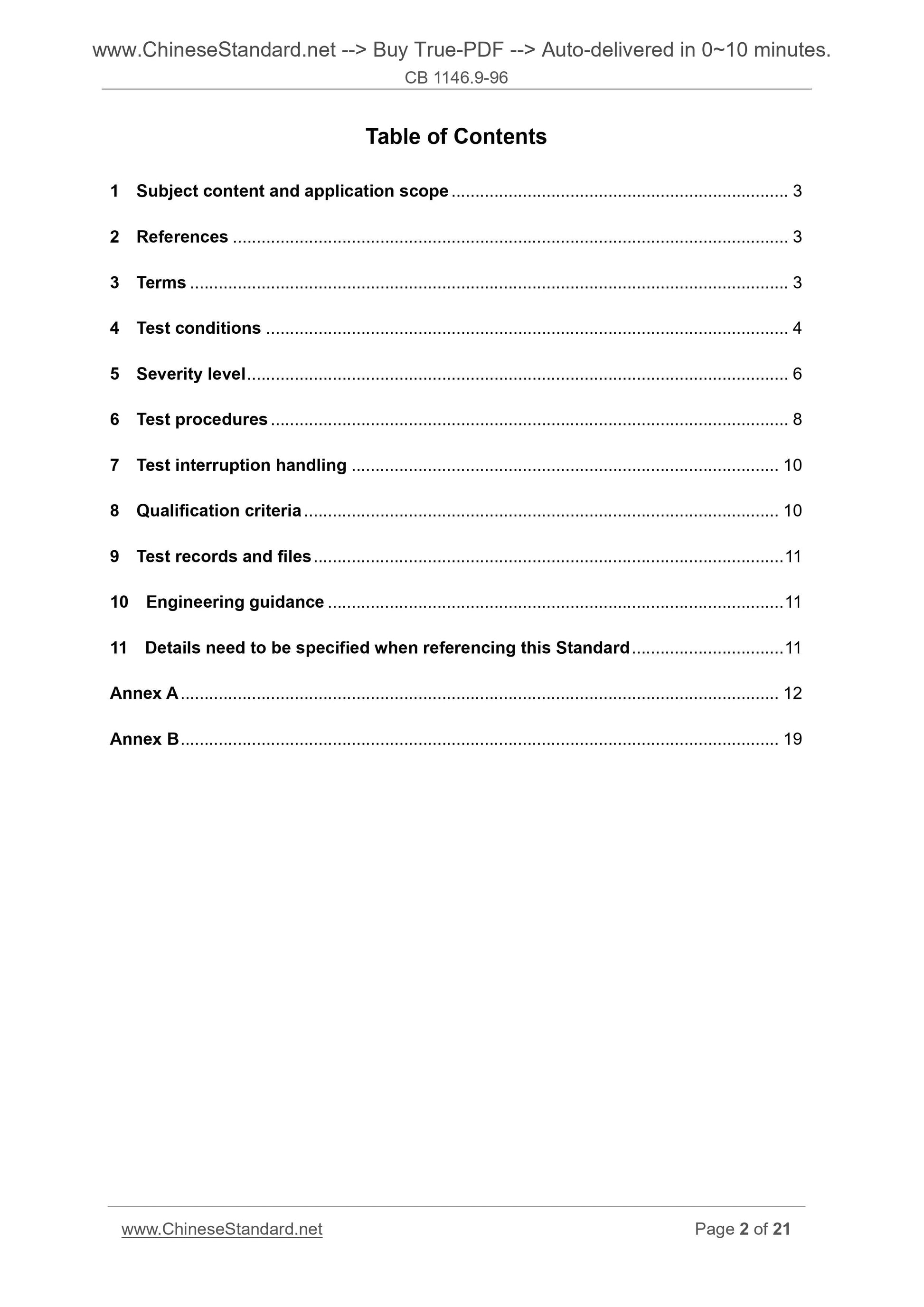
Table of Contents
1 Subject content and application scope ... 3
2 References ... 3
3 Terms ... 3
4 Test conditions ... 4
5 Severity level ... 6
6 Test procedures ... 8
7 Test interruption handling ... 10
8 Qualification criteria ... 10
9 Test records and files ... 11
10 Engineering guidance ... 11
11 Details need to be specified when referencing this Standard ... 11
Annex A ... 12
Annex B ... 19
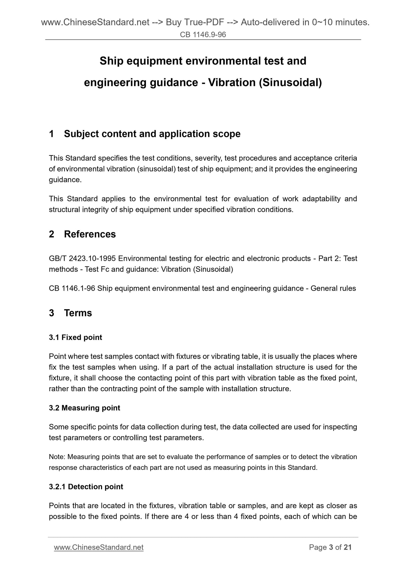
Ship equipment environmental test and
engineering guidance - Vibration (Sinusoidal)
1 Subject content and application scope
This Standard specifies the test conditions, severity, test procedures and acceptance criteria
of environmental vibration (sinusoidal) test of ship equipment; and it provides the engineering
guidance.
This Standard applies to the environmental test for evaluation of work adaptability and
structural integrity of ship equipment under specified vibration conditions.
2 References
GB/T 2423.10-1995 Environmental testing for electric and electronic products - Part 2. Test
methods - Test Fc and guidance. Vibration (Sinusoidal)
CB 1146.1-96 Ship equipment environmental test and engineering guidance - General rules
3 Terms
3.1 Fixed point
Point where test samples contact with fixtures or vibrating table, it is usually the places where
fix the test samples when using. If a part of the actual installation structure is used for the
fixture, it shall choose the contacting point of this part with vibration table as the fixed point,
rather than the contracting point of the sample with installation structure.
3.2 Measuring point
Some specific points for data collection during test, the data collected are used for inspecting
test parameters or controlling test parameters.
Note. Measuring points that are set to evaluate the performance of samples or to detect the vibration
response characteristics of each part are not used as measuring points in this Standard.
3.2.1 Detection point
Points that are located in the fixtures, vibration table or samples, and are kept as closer as
possible to the fixed points. If there are 4 or less than 4 fixed points, each of which can be
taken as a detection point; if there are more than 4 fixed points, then the relevant standards
shall specify 4 representative fixed points as the detection points.
Under special circumstances, such as large or complex samples, if the detection points are
required to be at other places (not close to fixed points), then it shall be specified by relevant
standards, or determined by test engineering.
When several small samples are mounted onto a fixture, or when a small sample having a
number of fixed points, in order to derive the control signal, it can choose a single detection
point, which shall be selected from the fixed points of samples and fixtures, not the fixed
points of fixtures and vibration table. This is feasible only when the lowest resonant frequency
exceeds the upper-limit of the test frequency after the sample is mounted onto the fixture.
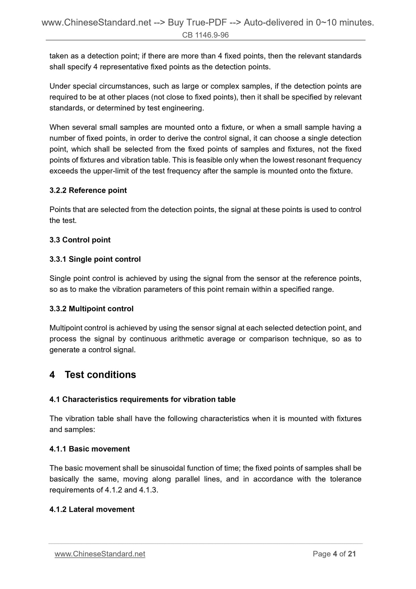
3.2.2 Reference point
Points that are selected from the detection points, the signal at these points is used to control
the test.
3.3 Control point
3.3.1 Single point control
Single point control is achieved by using the signal from the sensor at the reference points,
so as to make the vibration parameters of this point remain within a specified range.
3.3.2 Multipoint control
Multipoint control is achieved by using the sensor signal at each selected detection point, and
process the signal by continuous arithmetic average or comparison technique, so as to
generate a control signal.
4 Test conditions
4.1 Characteristics requirements for vibration table
The vibration table shall have the following characteristics when it is mounted with fixtures
and samples.
4.1.1 Basic movement
The basic movement shall be sinusoidal function of time; the fixed points of samples shall be
basically the same, moving along parallel lines, and in accordance with the tolerance
requirements of 4.1.2 and 4.1.3.
4.1.2 Lateral movement
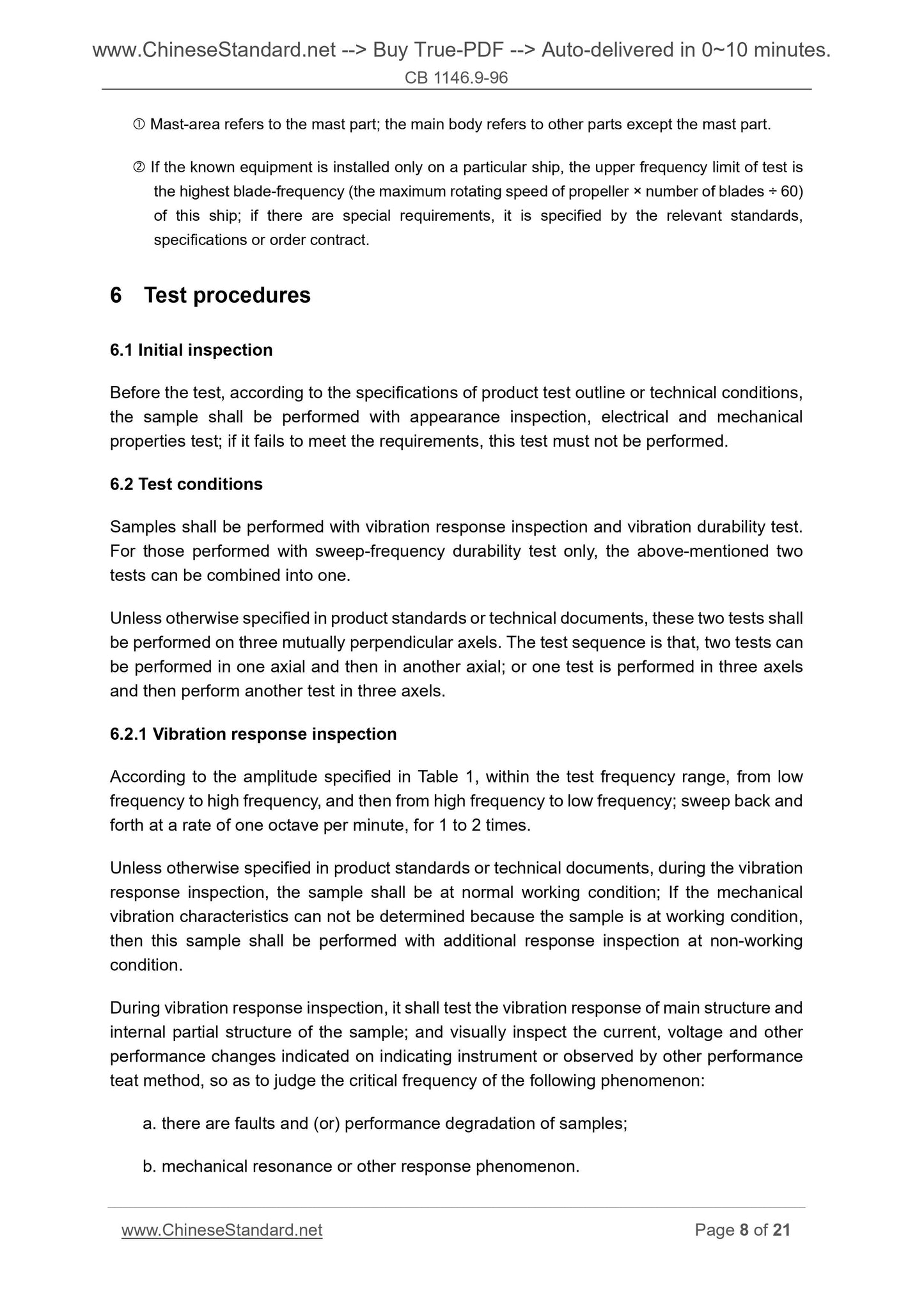
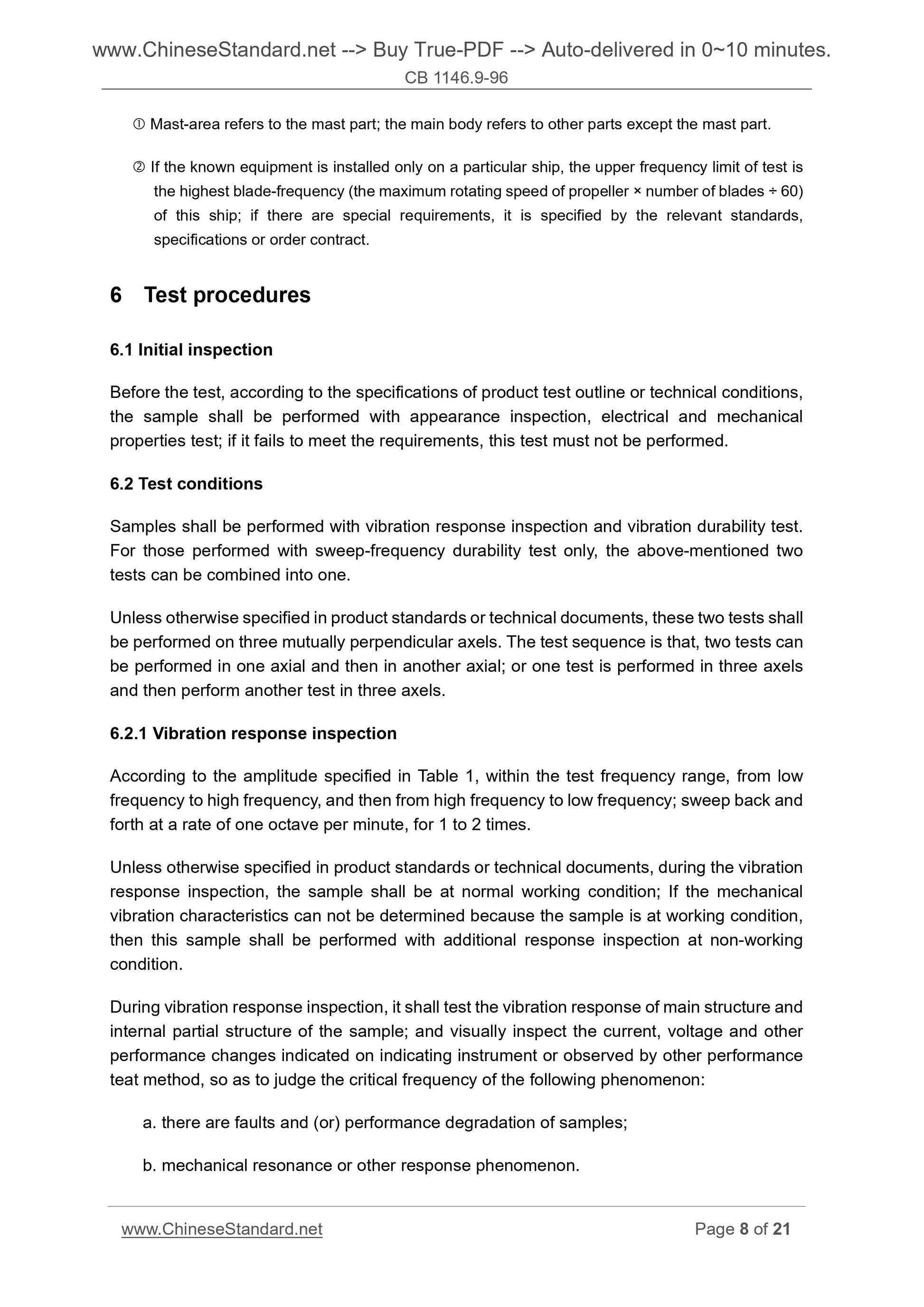
Mast-area refers to the mast part; the main body refers to other parts except the mast part.
If the known equipment is installed only on a particular ship, the upper frequency limit of test is
the highest blade-frequency (the maximum rotating speed of propeller × number of blades ÷ 60)
of this ship; if there are special requirements, it is specified by the relevant standards,
specifications or order contract.
6 Test procedures
6.1 Initial inspection
Before the test, according to the specifications of product test outline or technical conditions,
the sample shall be performed with appearance inspection, electrical and mechanical
properties test; if it fails to meet the requirements, this test must not be performed.
6.2 Test conditions
Samples shall be performed with vibration response inspection and vibration durability test.
For those performed with sweep-frequency durability test only, the above-mentioned two
tests can be combined into one.
Unless otherwise specified in product standards or technical documents, these two tests shall
be performed on three mutually perpendicular axels. The test sequence is that, two tests can
be performed in one axial and then in another axial; or one test is performed in three axels
and then perform another test in three axels.
6.2.1 Vibration response inspection
According to the amplitude specified in Table 1, within the test frequency range, from low
frequency to high frequency, and then from high frequency to low frequency; sweep back and
forth at a rate of one octave per minute, for 1 to 2 times.
Unless otherwise specified in product standards or technical documents, during the vibration
response inspection, the sample shall be at normal working condition; If the mechanical
vibration characteristics can not be determined because the sample is at working condition,
then this sample shall be performed with additional response inspection at non-working
condition.
During vibration response inspection, it shall test the vibration response of main structure and
internal partial structure of the sample; and visually inspect the current, voltage and other
performance changes indicated on indicating instrument or observed by other performance
teat method, so as to judge the critical frequency of the following phenomenon.
a. there are faults and (or) performance degradation of samples;
b. mechanical resonance or other response phenomenon.
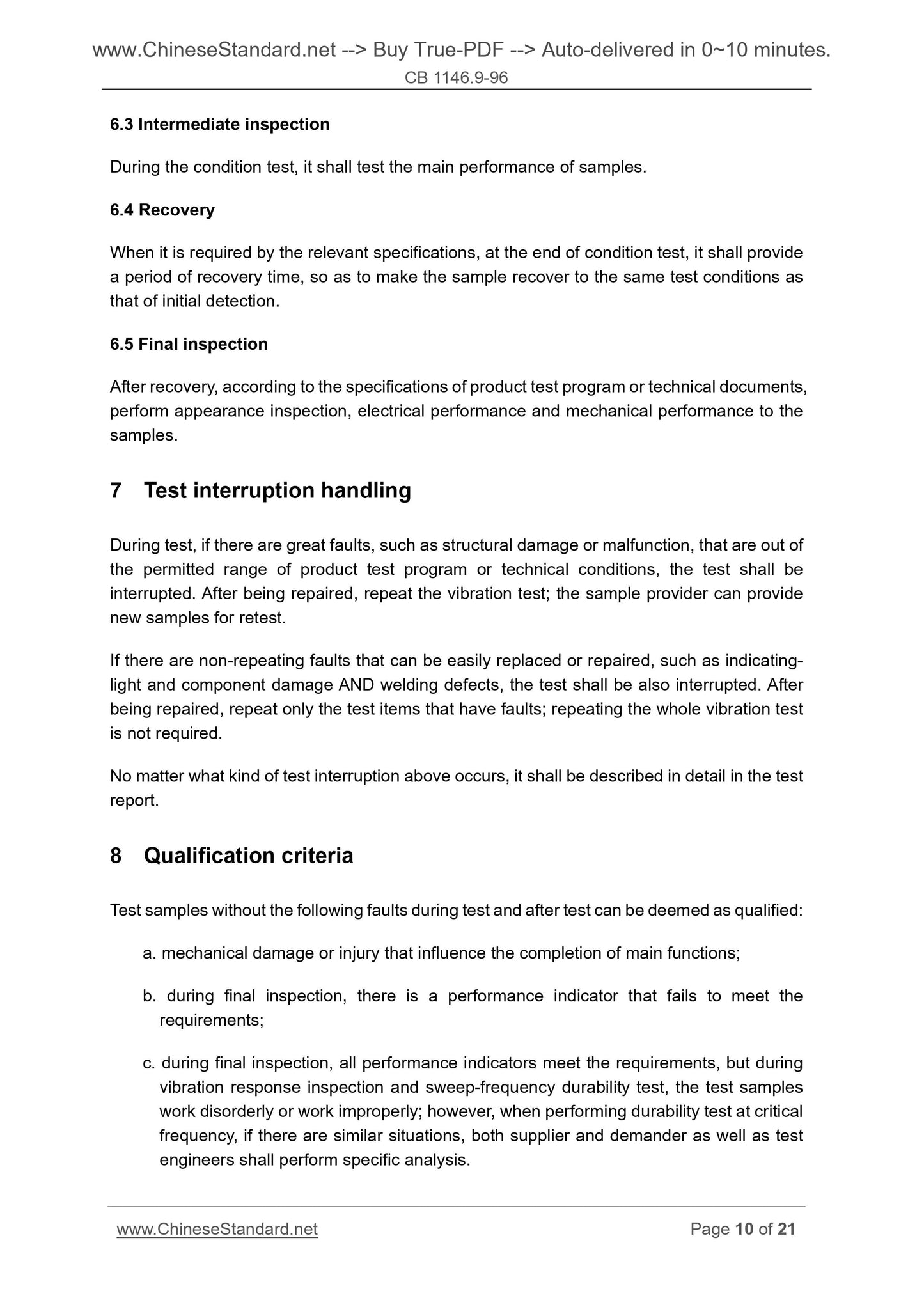
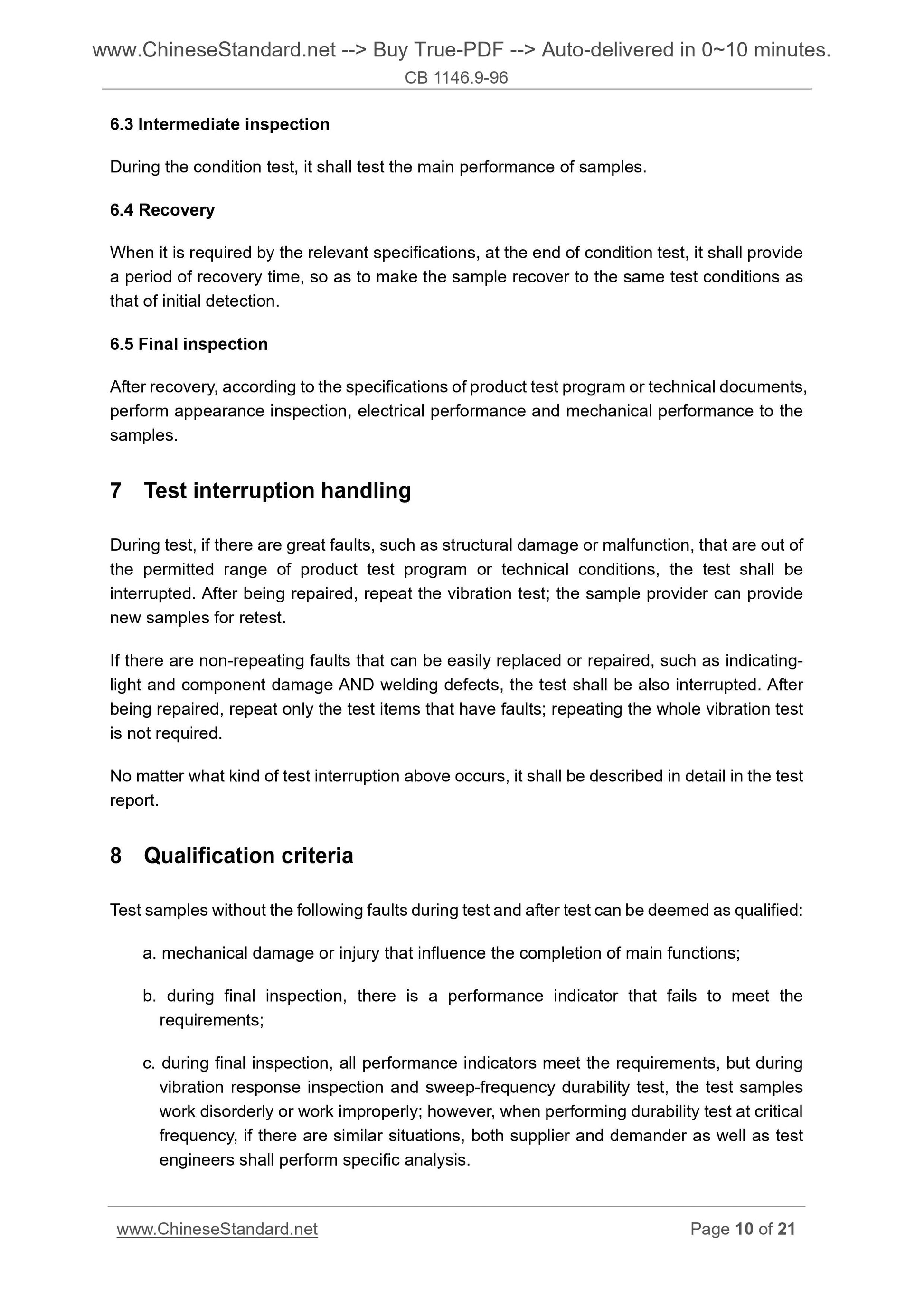
6.3 Intermediate inspection
During the condition test, it shall test the main performance of samples.
6.4 Recovery
When it is required by the relevant specifications, at the end of condition test, it shall provide
a period of recovery time, so as to make the sample recover to the same test conditions as
that of initial detection.
6.5 Final inspection
After recovery, according to the specifications of product test program or technical documents,
perform appearance inspection, electrical performance and mechanical performance to the
samples.
7 Test interruption handling
During test, if there are great faults, such as structural damage or malfunction, that are out of
the permitted range of product test program or technical conditions, the test shall be
interrupted. After being repaired, repeat the vibration test; the sample provider can provide
new samples for retest.
If there are non-repeating faults that can be easily replaced or repaired, such as indicating-
light and component damage AND welding defects, the test shall be also interrupted. After
being repaired, repeat only the test items that have faults; repeating the whole vibration test
is not required.
No matter what kind of test interruption above occurs, it shall be described in detail in the test
report.
8 Qualification criteria
Test samples without the following faults during test and after test can be deemed as qualified.
a. mechanical damage or injury that influence the completion of main functions;
b. during final inspection, there is a performance indicator that fails to meet the
requirements;
c. during final inspection, all performance indicators meet the requirements, but during
vibration response inspection and sweep-frequency dura...
CB 1146.9-96
CB
MINISTERIAL STANDARD OF
CHINA SHIPBUILDING CORPORATION
U08
Replacing CB 1146.9-85
Ship equipment environmental test and engineering
guidance - Vibration (Sinusoidal)
ISSUED ON. DECEMBER 23, 1996
IMPLEMENTED ON. JUNE 1, 1997
Issued by. China Shipbuilding Corporation
Table of Contents
1 Subject content and application scope ... 3
2 References ... 3
3 Terms ... 3
4 Test conditions ... 4
5 Severity level ... 6
6 Test procedures ... 8
7 Test interruption handling ... 10
8 Qualification criteria ... 10
9 Test records and files ... 11
10 Engineering guidance ... 11
11 Details need to be specified when referencing this Standard ... 11
Annex A ... 12
Annex B ... 19
Ship equipment environmental test and
engineering guidance - Vibration (Sinusoidal)
1 Subject content and application scope
This Standard specifies the test conditions, severity, test procedures and acceptance criteria
of environmental vibration (sinusoidal) test of ship equipment; and it provides the engineering
guidance.
This Standard applies to the environmental test for evaluation of work adaptability and
structural integrity of ship equipment under specified vibration conditions.
2 References
GB/T 2423.10-1995 Environmental testing for electric and electronic products - Part 2. Test
methods - Test Fc and guidance. Vibration (Sinusoidal)
CB 1146.1-96 Ship equipment environmental test and engineering guidance - General rules
3 Terms
3.1 Fixed point
Point where test samples contact with fixtures or vibrating table, it is usually the places where
fix the test samples when using. If a part of the actual installation structure is used for the
fixture, it shall choose the contacting point of this part with vibration table as the fixed point,
rather than the contracting point of the sample with installation structure.
3.2 Measuring point
Some specific points for data collection during test, the data collected are used for inspecting
test parameters or controlling test parameters.
Note. Measuring points that are set to evaluate the performance of samples or to detect the vibration
response characteristics of each part are not used as measuring points in this Standard.
3.2.1 Detection point
Points that are located in the fixtures, vibration table or samples, and are kept as closer as
possible to the fixed points. If there are 4 or less than 4 fixed points, each of which can be
taken as a detection point; if there are more than 4 fixed points, then the relevant standards
shall specify 4 representative fixed points as the detection points.
Under special circumstances, such as large or complex samples, if the detection points are
required to be at other places (not close to fixed points), then it shall be specified by relevant
standards, or determined by test engineering.
When several small samples are mounted onto a fixture, or when a small sample having a
number of fixed points, in order to derive the control signal, it can choose a single detection
point, which shall be selected from the fixed points of samples and fixtures, not the fixed
points of fixtures and vibration table. This is feasible only when the lowest resonant frequency
exceeds the upper-limit of the test frequency after the sample is mounted onto the fixture.
3.2.2 Reference point
Points that are selected from the detection points, the signal at these points is used to control
the test.
3.3 Control point
3.3.1 Single point control
Single point control is achieved by using the signal from the sensor at the reference points,
so as to make the vibration parameters of this point remain within a specified range.
3.3.2 Multipoint control
Multipoint control is achieved by using the sensor signal at each selected detection point, and
process the signal by continuous arithmetic average or comparison technique, so as to
generate a control signal.
4 Test conditions
4.1 Characteristics requirements for vibration table
The vibration table shall have the following characteristics when it is mounted with fixtures
and samples.
4.1.1 Basic movement
The basic movement shall be sinusoidal function of time; the fixed points of samples shall be
basically the same, moving along parallel lines, and in accordance with the tolerance
requirements of 4.1.2 and 4.1.3.
4.1.2 Lateral movement
Mast-area refers to the mast part; the main body refers to other parts except the mast part.
If the known equipment is installed only on a particular ship, the upper frequency limit of test is
the highest blade-frequency (the maximum rotating speed of propeller × number of blades ÷ 60)
of this ship; if there are special requirements, it is specified by the relevant standards,
specifications or order contract.
6 Test procedures
6.1 Initial inspection
Before the test, according to the specifications of product test outline or technical conditions,
the sample shall be performed with appearance inspection, electrical and mechanical
properties test; if it fails to meet the requirements, this test must not be performed.
6.2 Test conditions
Samples shall be performed with vibration response inspection and vibration durability test.
For those performed with sweep-frequency durability test only, the above-mentioned two
tests can be combined into one.
Unless otherwise specified in product standards or technical documents, these two tests shall
be performed on three mutually perpendicular ax...
Share
