1
/
of
12
PayPal, credit cards. Download editable-PDF & invoice in 1 second!
GB 15930-2007 English PDF (GB15930-2007)
GB 15930-2007 English PDF (GB15930-2007)
Regular price
$130.00 USD
Regular price
Sale price
$130.00 USD
Unit price
/
per
Shipping calculated at checkout.
Couldn't load pickup availability
Delivery: 3 seconds. Download true-PDF + Invoice.
Get QUOTATION in 1-minute: Click GB 15930-2007
Historical versions: GB 15930-2007
Preview True-PDF (Reload/Scroll if blank)
GB 15930-2007: Fire dampers for building venting and smoke-venting system
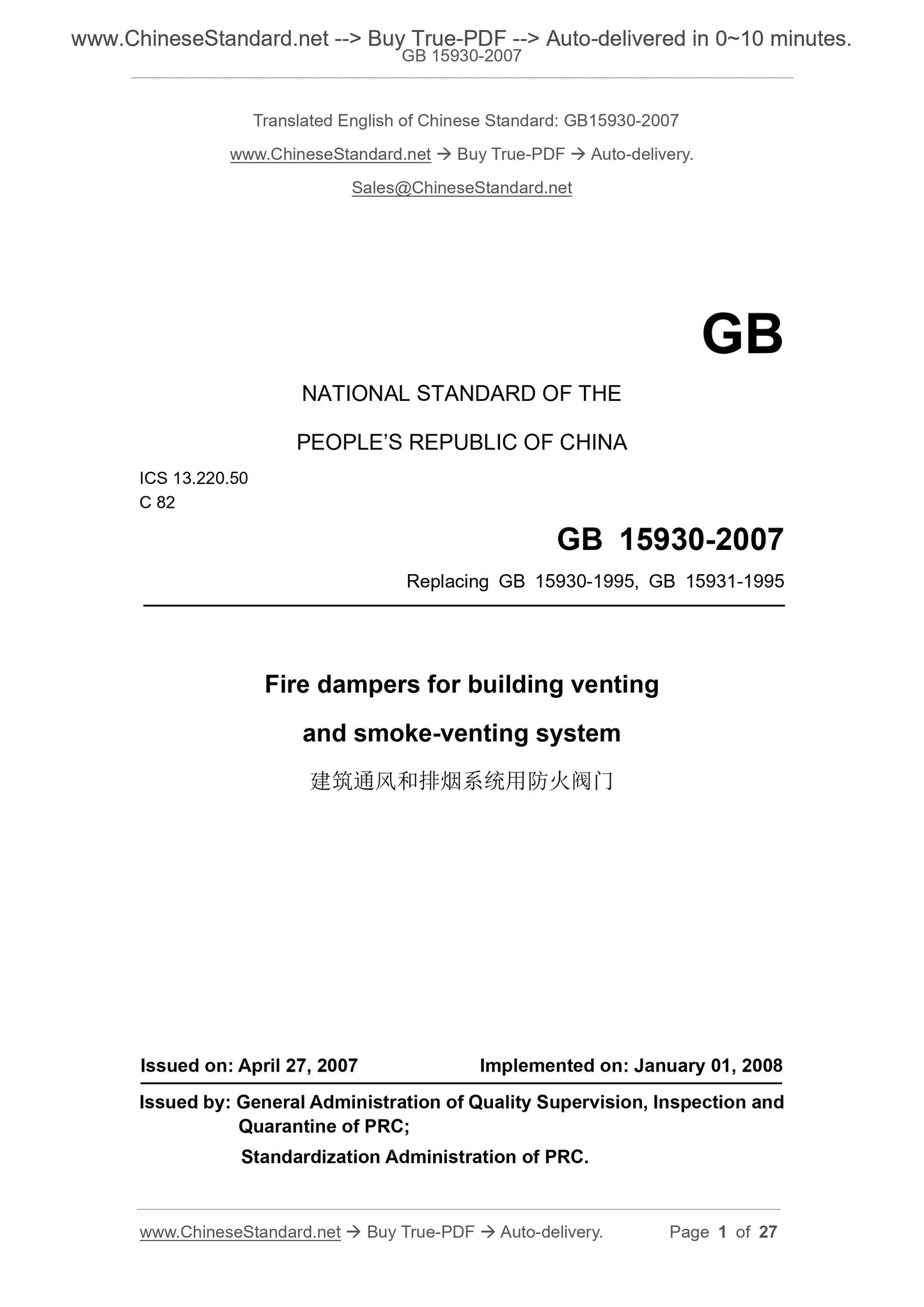
GB 15930-2007
NATIONAL STANDARD OF THE
PEOPLE’S REPUBLIC OF CHINA
ICS 13.220.50
C 82
Replacing GB 15930-1995, GB 15931-1995
Fire dampers for building venting
and smoke-venting system
ISSUED ON: APRIL 27, 2007
IMPLEMENTED ON: JANUARY 01, 2008
Issued by: General Administration of Quality Supervision, Inspection and
Quarantine of PRC;
Standardization Administration of PRC.
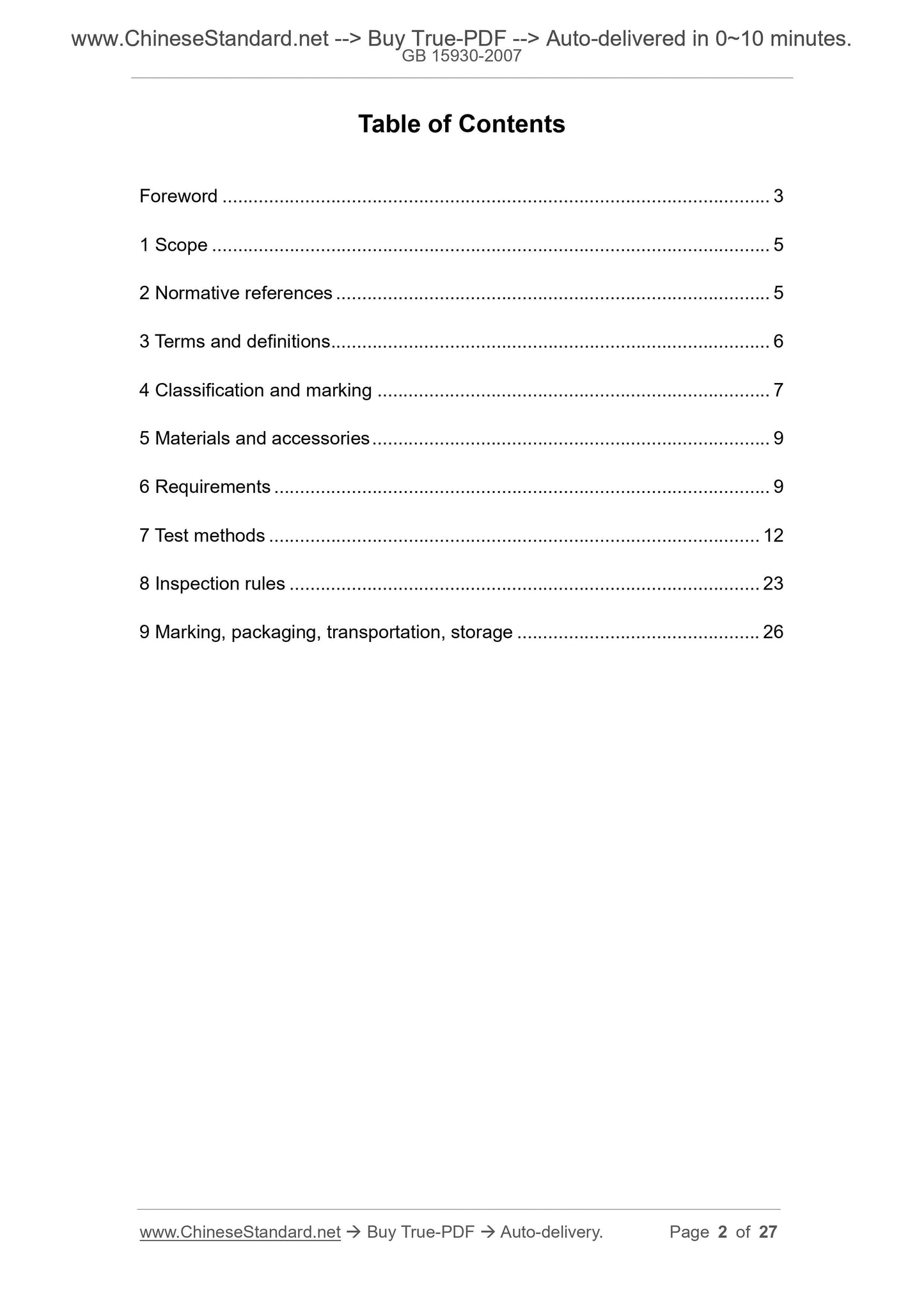
Table of Contents
Foreword ... 3
1 Scope ... 5
2 Normative references ... 5
3 Terms and definitions ... 6
4 Classification and marking ... 7
5 Materials and accessories ... 9
6 Requirements ... 9
7 Test methods ... 12
8 Inspection rules ... 23
9 Marking, packaging, transportation, storage ... 26
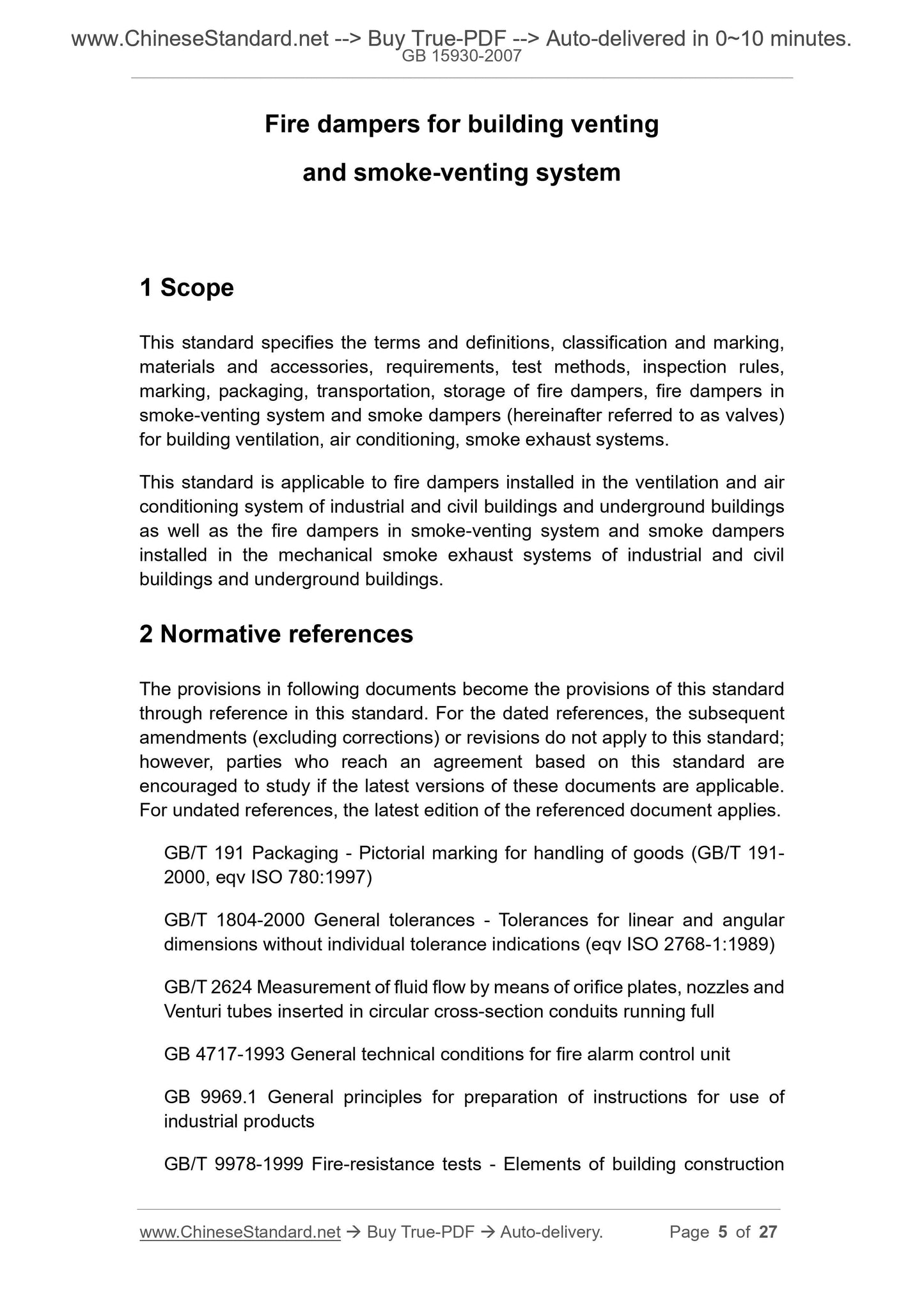
Fire dampers for building venting
and smoke-venting system
1 Scope
This standard specifies the terms and definitions, classification and marking,
materials and accessories, requirements, test methods, inspection rules,
marking, packaging, transportation, storage of fire dampers, fire dampers in
smoke-venting system and smoke dampers (hereinafter referred to as valves)
for building ventilation, air conditioning, smoke exhaust systems.
This standard is applicable to fire dampers installed in the ventilation and air
conditioning system of industrial and civil buildings and underground buildings
as well as the fire dampers in smoke-venting system and smoke dampers
installed in the mechanical smoke exhaust systems of industrial and civil
buildings and underground buildings.
2 Normative references
The provisions in following documents become the provisions of this standard
through reference in this standard. For the dated references, the subsequent
amendments (excluding corrections) or revisions do not apply to this standard;
however, parties who reach an agreement based on this standard are
encouraged to study if the latest versions of these documents are applicable.
For undated references, the latest edition of the referenced document applies.
GB/T 191 Packaging - Pictorial marking for handling of goods (GB/T 191-
2000, eqv ISO 780:1997)
GB/T 1804-2000 General tolerances - Tolerances for linear and angular
dimensions without individual tolerance indications (eqv ISO 2768-1:1989)
GB/T 2624 Measurement of fluid flow by means of orifice plates, nozzles and
Venturi tubes inserted in circular cross-section conduits running full
GB 4717-1993 General technical conditions for fire alarm control unit
GB 9969.1 General principles for preparation of instructions for use of
industrial products
GB/T 9978-1999 Fire-resistance tests - Elements of building construction
(neq ISO/FDIS 834-1:1997)
GB/T 13306 Plates
GB/T 13384 General specification for packaging of mechanical and electrical
products
GB/T 14436 General principles of industrial product guarantee documents
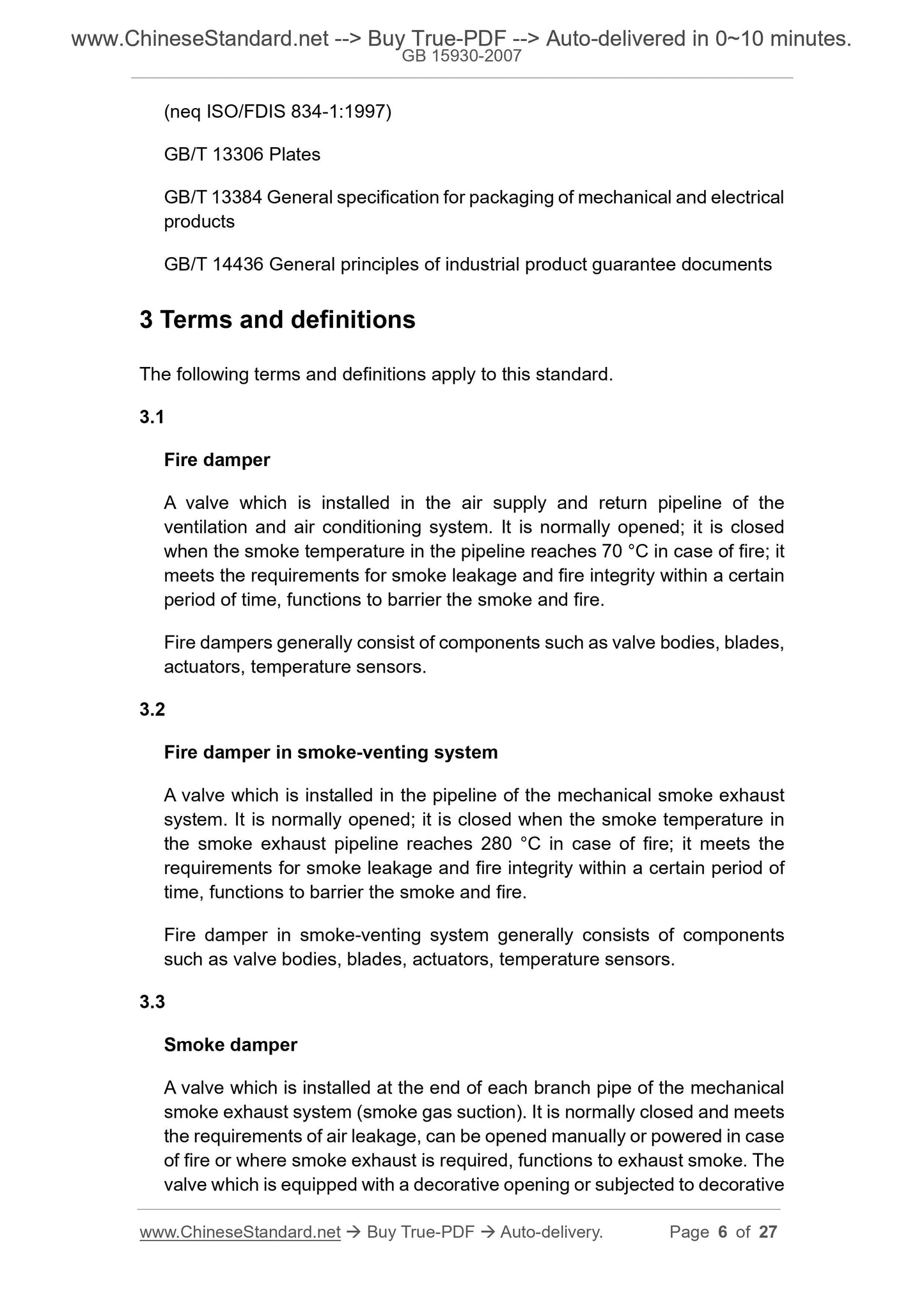
3 Terms and definitions
The following terms and definitions apply to this standard.
3.1
Fire damper
A valve which is installed in the air supply and return pipeline of the
ventilation and air conditioning system. It is normally opened; it is closed
when the smoke temperature in the pipeline reaches 70 °C in case of fire; it
meets the requirements for smoke leakage and fire integrity within a certain
period of time, functions to barrier the smoke and fire.
Fire dampers generally consist of components such as valve bodies, blades,
actuators, temperature sensors.
3.2
Fire damper in smoke-venting system
A valve which is installed in the pipeline of the mechanical smoke exhaust
system. It is normally opened; it is closed when the smoke temperature in
the smoke exhaust pipeline reaches 280 °C in case of fire; it meets the
requirements for smoke leakage and fire integrity within a certain period of
time, functions to barrier the smoke and fire.
Fire damper in smoke-venting system generally consists of components
such as valve bodies, blades, actuators, temperature sensors.
3.3
Smoke damper
A valve which is installed at the end of each branch pipe of the mechanical
smoke exhaust system (smoke gas suction). It is normally closed and meets
the requirements of air leakage, can be opened manually or powered in case
of fire or where smoke exhaust is required, functions to exhaust smoke. The
valve which is equipped with a decorative opening or subjected to decorative
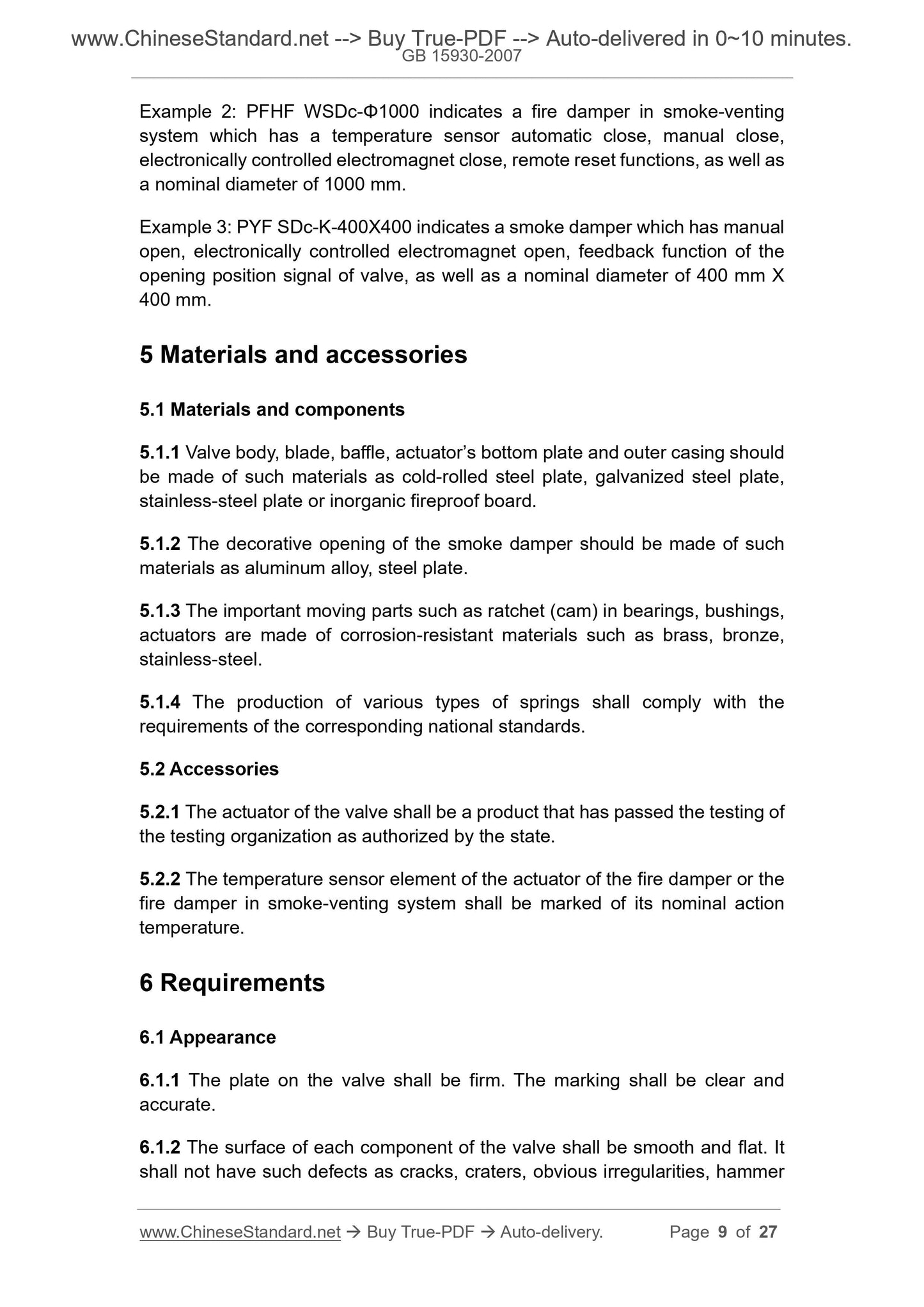
Example 2: PFHF WSDc-Φ1000 indicates a fire damper in smoke-venting
system which has a temperature sensor automatic close, manual close,
electronically controlled electromagnet close, remote reset functions, as well as
a nominal diameter of 1000 mm.
Example 3: PYF SDc-K-400X400 indicates a smoke damper which has manual
open, electronically controlled electromagnet open, feedback function of the
opening position signal of valve, as well as a nominal diameter of 400 mm X
400 mm.
5 Materials and accessories
5.1 Materials and components
5.1.1 Valve body, blade, baffle, actuator’s bottom plate and outer casing should
be made of such materials as cold-rolled steel plate, galvanized steel plate,
stainless-steel plate or inorganic fireproof board.
5.1.2 The decorative opening of the smoke damper should be made of such
materials as aluminum alloy, steel plate.
5.1.3 The important moving parts such as ratchet (cam) in bearings, bushings,
actuators are made of corrosion-resistant materials such as brass, bronze,
stainless-steel.
5.1.4 The production of various types of springs shall comply with the
requirements of the corresponding national standards.
5.2 Accessories
5.2.1 The actuator of the valve shall be a product that has passed the testing of
the testing organization as authorized by the state.
5.2.2 The temperature sensor element of the actuator of the fire damper or the
fire damper in smoke-venting system shall be marked of its nominal action
temperature.
6 Requirements
6.1 Appearance
6.1.1 The plate on the valve shall be firm. The marking shall be clear and
accurate.
6.1.2 The surface of each component of the valve shall be smooth and flat. It
shall not have such defects as cracks, craters, obvious irregularities, hammer
6.6 Manual control
6.6.1 Fire damper or fire damper in smoke-venting system should have manual
closing mode. the smoke damper shall have manual opening mode. Manual
operation shall be convenient, flexible, reliable.
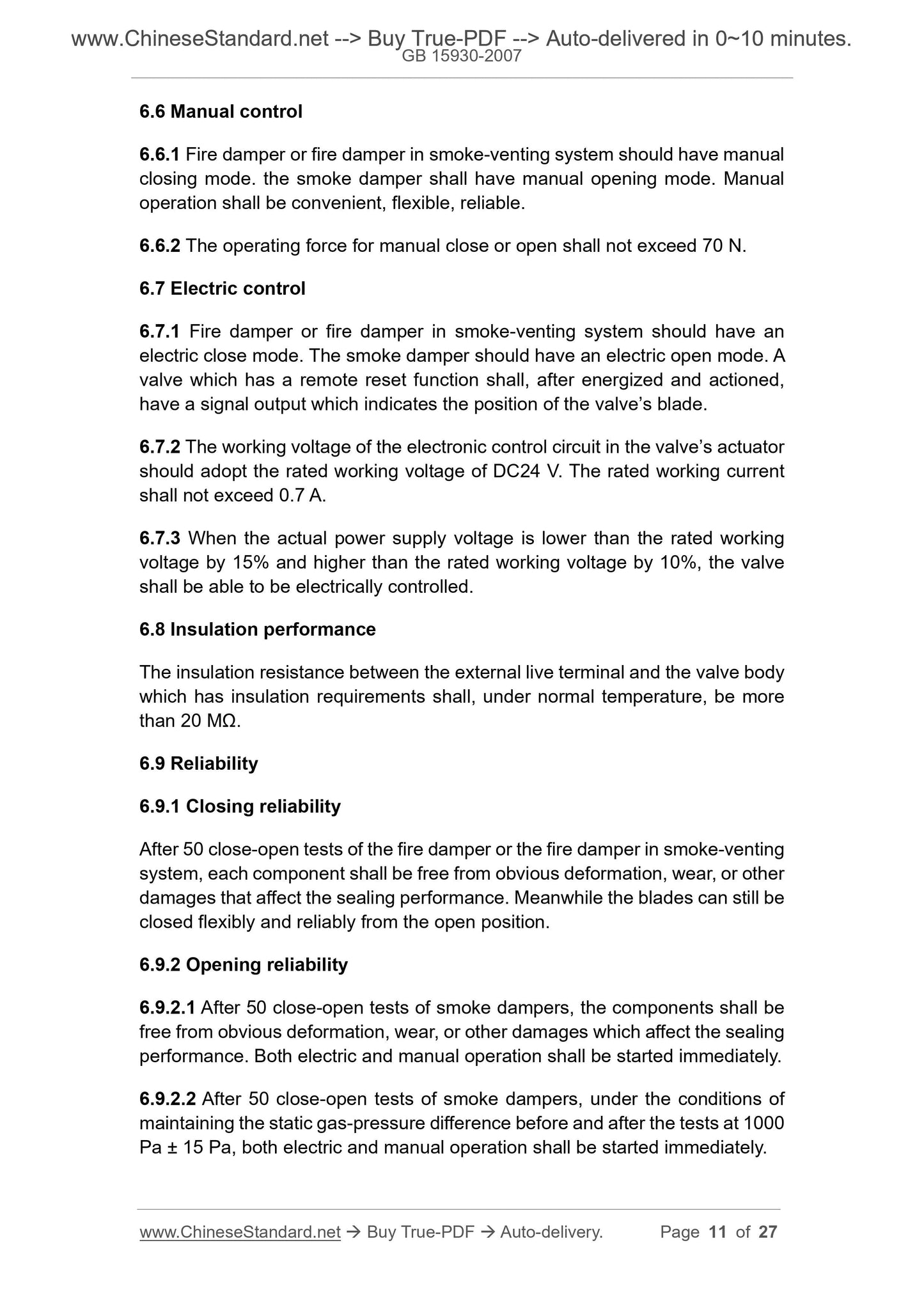
6.6.2 The operating force for manual close or open shall not exceed 70 N.
6.7 Electric control
6.7.1 Fire damper or fire damper in smoke-venting system should have an
electric close mode. The smoke damper should have an electric open mode. A
valve which has a remote reset function shall, after energized and actioned,
have a signal output which indicates the position of the valve’s blade.
6.7.2 The working voltage of the electronic control circuit in the valve’s actuator
should adopt the rated working voltage of DC24 V. The rated working current
shall not exceed 0.7 A.
6.7.3 When the actual power supply voltage is lower than the rated working
voltage by 15% and higher than the rated working voltage by 10%, the valve
shall be able to be electrically controlled.
6.8 Insulation performance
The insulation resistance between the external live terminal and the valve body
which has insulation requirements shall, under normal temperature, be more
than 20 MΩ.
6.9 Reliability
6.9.1 Closing reliability
After 50 close-open tests of the fire damper or the fire damper in smoke-venting
sys...
Share
