1
/
of
6
www.ChineseStandard.us -- Field Test Asia Pte. Ltd.
GB/T 10095.1-2022 English PDF (GB/T10095.1-2022)
GB/T 10095.1-2022 English PDF (GB/T10095.1-2022)
Regular price
$605.00
Regular price
Sale price
$605.00
Unit price
/
per
Shipping calculated at checkout.
Couldn't load pickup availability
GB/T 10095.1-2022: Cylindrical gears - ISO system of flank tolerance classification - Part 1: Definitions and allowable values of deviations relevant to flanks of gear teeth
Delivery: 9 seconds. Download (& Email) true-PDF + Invoice.
Get Quotation: Click GB/T 10095.1-2022 (Self-service in 1-minute)
Historical versions (Master-website): GB/T 10095.1-2022
Preview True-PDF (Reload/Scroll-down if blank)
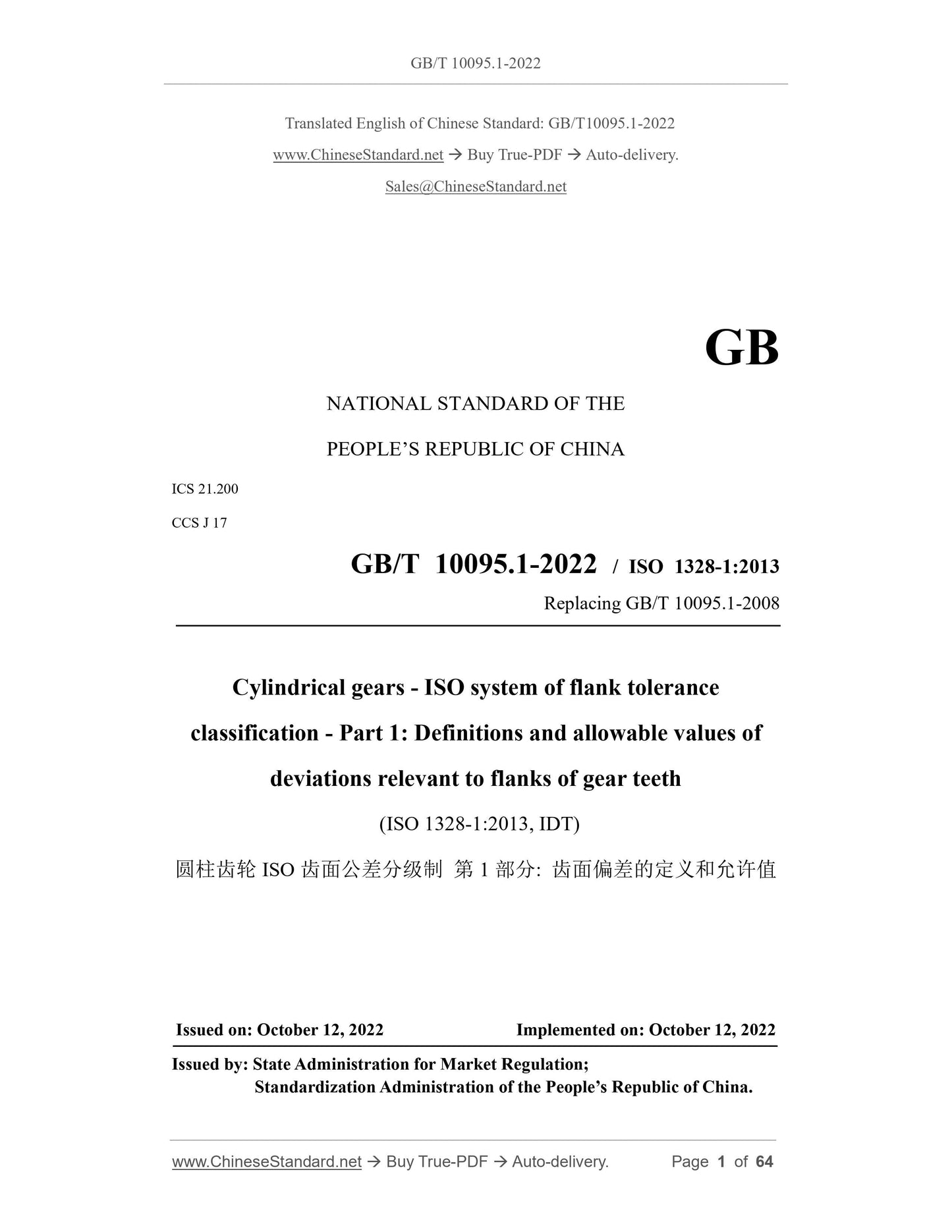
GB/T 10095.1-2022
GB
NATIONAL STANDARD OF THE
PEOPLE’S REPUBLIC OF CHINA
ICS 21.200
CCS J 17
GB/T 10095.1-2022 / ISO 1328-1:2013
Replacing GB/T 10095.1-2008
Cylindrical gears - ISO system of flank tolerance
classification - Part 1: Definitions and allowable values of
deviations relevant to flanks of gear teeth
(ISO 1328-1:2013, IDT)
ISSUED ON: OCTOBER 12, 2022
IMPLEMENTED ON: OCTOBER 12, 2022
Issued by: State Administration for Market Regulation;
Standardization Administration of the People’s Republic of China.
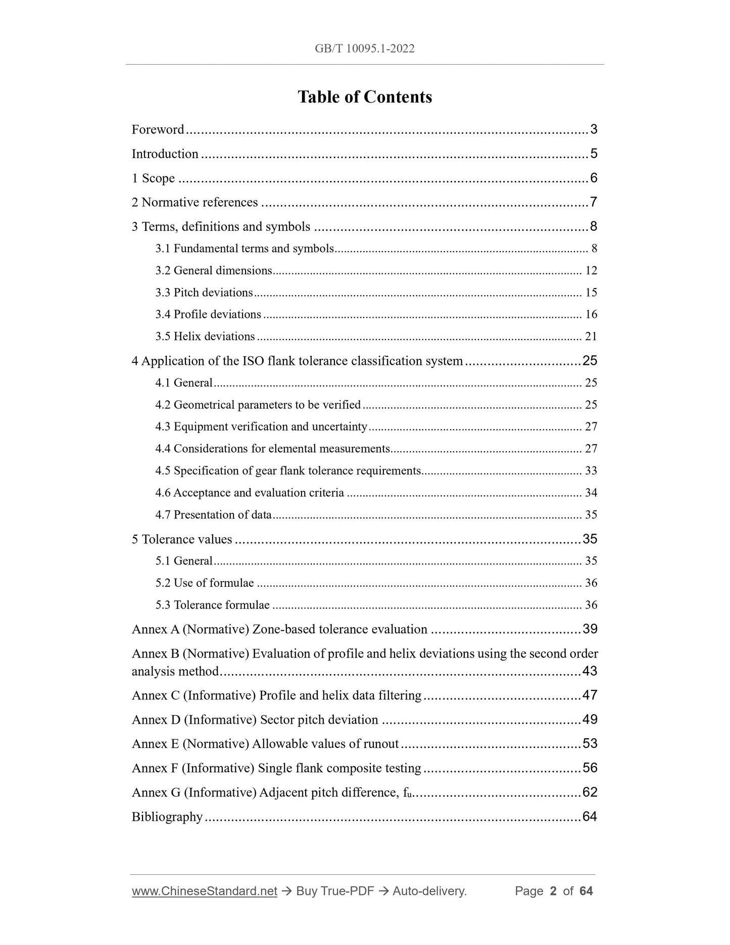
Table of Contents
Foreword ... 3
Introduction ... 5
1 Scope ... 6
2 Normative references ... 7
3 Terms, definitions and symbols ... 8
3.1 Fundamental terms and symbols ... 8
3.2 General dimensions ... 12
3.3 Pitch deviations ... 15
3.4 Profile deviations ... 16
3.5 Helix deviations ... 21
4 Application of the ISO flank tolerance classification system ... 25
4.1 General ... 25
4.2 Geometrical parameters to be verified ... 25
4.3 Equipment verification and uncertainty ... 27
4.4 Considerations for elemental measurements ... 27
4.5 Specification of gear flank tolerance requirements ... 33
4.6 Acceptance and evaluation criteria ... 34
4.7 Presentation of data ... 35
5 Tolerance values ... 35
5.1 General ... 35
5.2 Use of formulae ... 36
5.3 Tolerance formulae ... 36
Annex A (Normative) Zone-based tolerance evaluation ... 39
Annex B (Normative) Evaluation of profile and helix deviations using the second order
analysis method ... 43
Annex C (Informative) Profile and helix data filtering ... 47
Annex D (Informative) Sector pitch deviation ... 49
Annex E (Normative) Allowable values of runout ... 53
Annex F (Informative) Single flank composite testing ... 56
Annex G (Informative) Adjacent pitch difference, fu ... 62
Bibliography ... 64
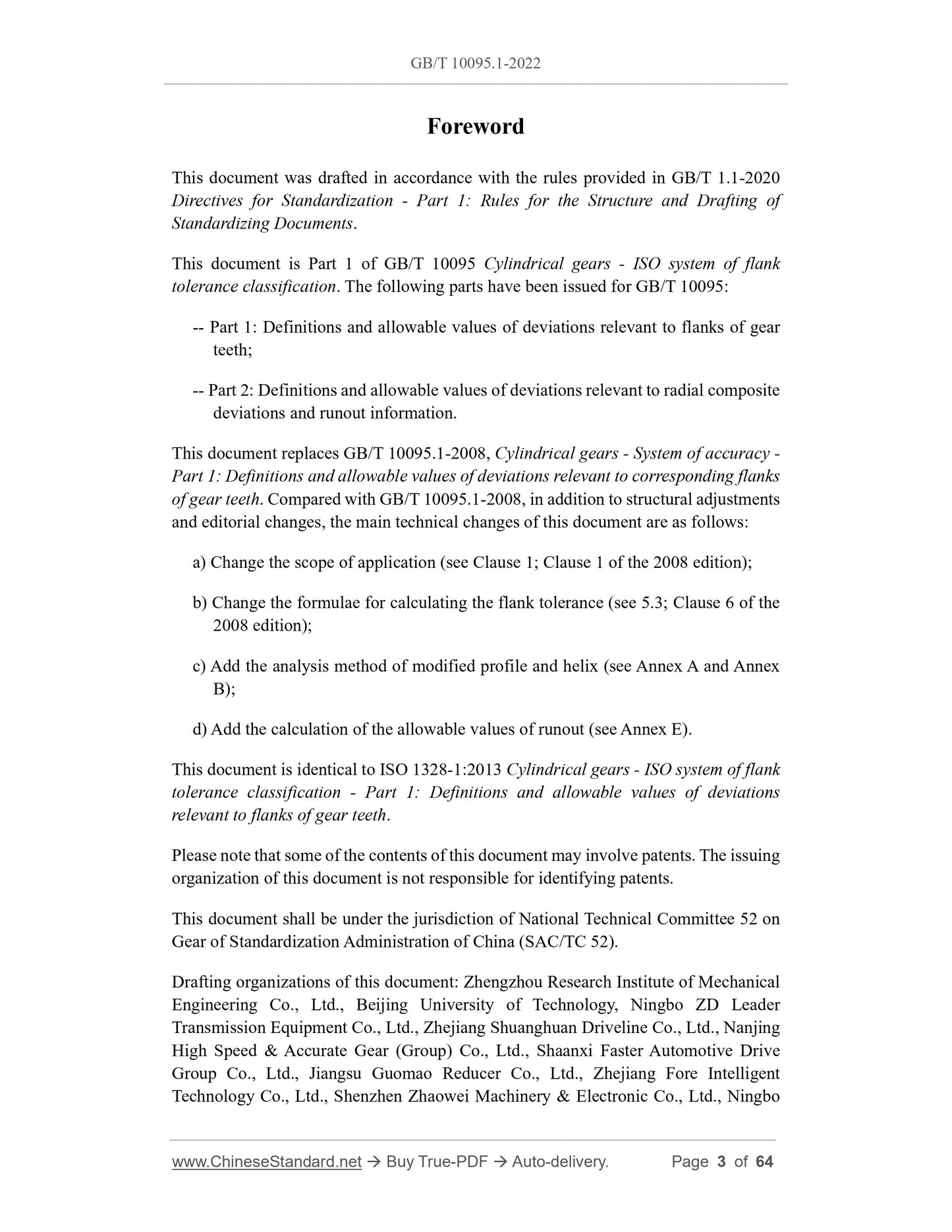
Foreword
This document was drafted in accordance with the rules provided in GB/T 1.1-2020
Directives for Standardization - Part 1: Rules for the Structure and Drafting of
Standardizing Documents.
This document is Part 1 of GB/T 10095 Cylindrical gears - ISO system of flank
tolerance classification. The following parts have been issued for GB/T 10095:
-- Part 1: Definitions and allowable values of deviations relevant to flanks of gear
teeth;
-- Part 2: Definitions and allowable values of deviations relevant to radial composite
deviations and runout information.
This document replaces GB/T 10095.1-2008, Cylindrical gears - System of accuracy -
Part 1: Definitions and allowable values of deviations relevant to corresponding flanks
of gear teeth. Compared with GB/T 10095.1-2008, in addition to structural adjustments
and editorial changes, the main technical changes of this document are as follows:
a) Change the scope of application (see Clause 1; Clause 1 of the 2008 edition);
b) Change the formulae for calculating the flank tolerance (see 5.3; Clause 6 of the
2008 edition);
c) Add the analysis method of modified profile and helix (see Annex A and Annex
B);
d) Add the calculation of the allowable values of runout (see Annex E).
This document is identical to ISO 1328-1:2013 Cylindrical gears - ISO system of flank
tolerance classification - Part 1: Definitions and allowable values of deviations
relevant to flanks of gear teeth.
Please note that some of the contents of this document may involve patents. The issuing
organization of this document is not responsible for identifying patents.
This document shall be under the jurisdiction of National Technical Committee 52 on
Gear of Standardization Administration of China (SAC/TC 52).
Drafting organizations of this document: Zhengzhou Research Institute of Mechanical
Engineering Co., Ltd., Beijing University of Technology, Ningbo ZD Leader
Transmission Equipment Co., Ltd., Zhejiang Shuanghuan Driveline Co., Ltd., Nanjing
High Speed and Accurate Gear (Group) Co., Ltd., Shaanxi Faster Automotive Drive
Group Co., Ltd., Jiangsu Guomao Reducer Co., Ltd., Zhejiang Fore Intelligent
Technology Co., Ltd., Shenzhen Zhaowei Machinery and Electronic Co., Ltd., Ningbo
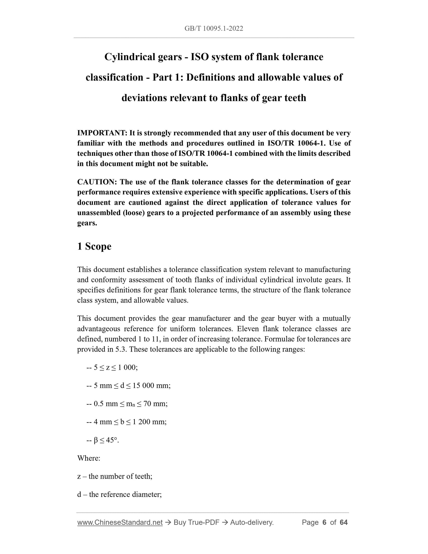
Cylindrical gears - ISO system of flank tolerance
classification - Part 1: Definitions and allowable values of
deviations relevant to flanks of gear teeth
IMPORTANT: It is strongly recommended that any user of this document be very
familiar with the methods and procedures outlined in ISO/TR 10064-1. Use of
techniques other than those of ISO/TR 10064-1 combined with the limits described
in this document might not be suitable.
CAUTION: The use of the flank tolerance classes for the determination of gear
performance requires extensive experience with specific applications. Users of this
document are cautioned against the direct application of tolerance values for
unassembled (loose) gears to a projected performance of an assembly using these
gears.
1 Scope
This document establishes a tolerance classification system relevant to manufacturing
and conformity assessment of tooth flanks of individual cylindrical involute gears. It
specifies definitions for gear flank tolerance terms, the structure of the flank tolerance
class system, and allowable values.
This document provides the gear manufacturer and the gear buyer with a mutually
advantageous reference for uniform tolerances. Eleven flank tolerance classes are
defined, numbered 1 to 11, in order of increasing tolerance. Formulae for tolerances are
provided in 5.3. These tolerances are applicable to the following ranges:
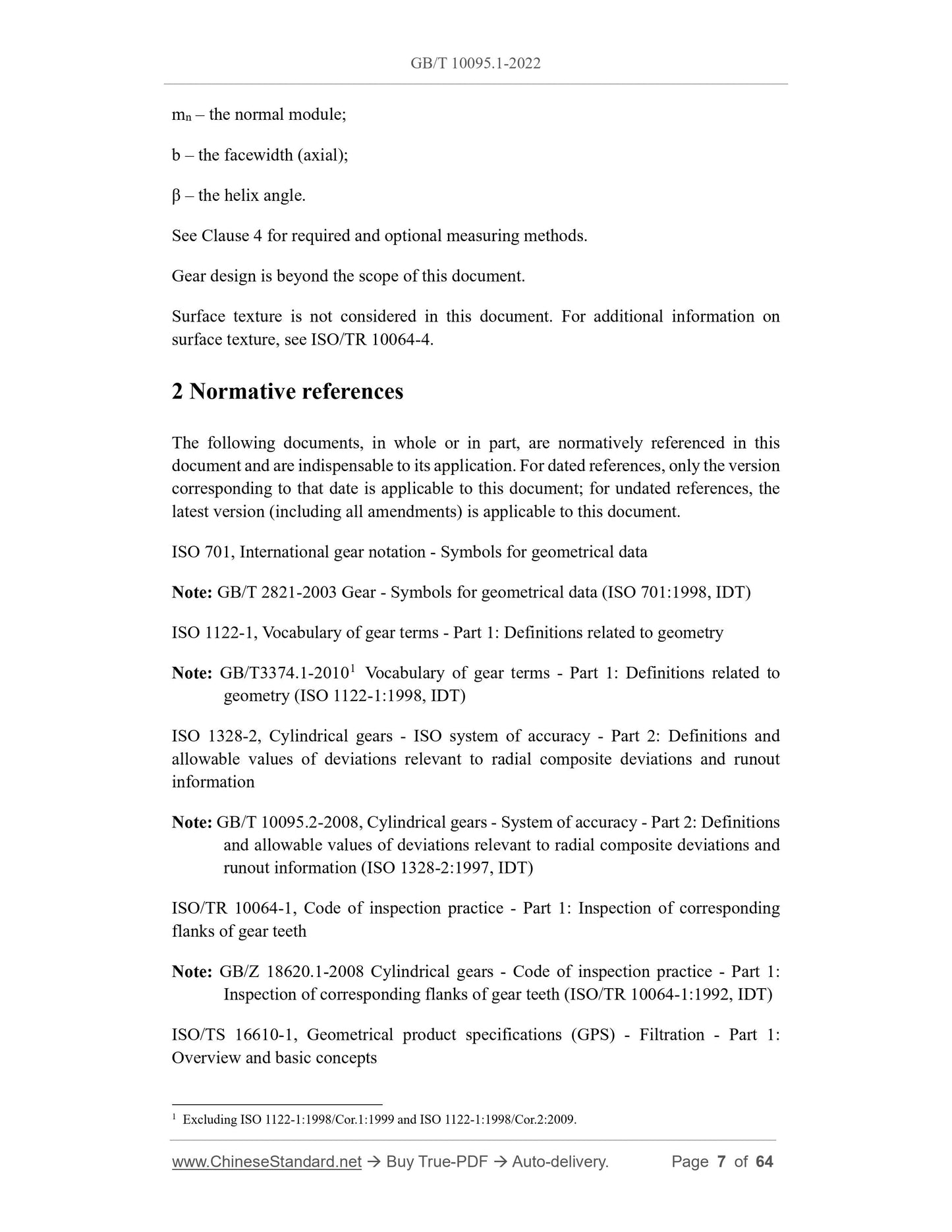
-- 5 ≤ z ≤ 1 000;
-- 5 mm ≤ d ≤ 15 000 mm;
-- 0.5 mm ≤ mn ≤ 70 mm;
-- 4 mm ≤ b ≤ 1 200 mm;
-- β ≤ 45°.
Where:
z – the number of teeth;
d – the reference diameter;
mn – the normal module;
b – the facewidth (axial);
β – the helix angle.
See Clause 4 for required and optional measuring methods.
Gear design is beyond the scope of this document.
Surface texture is not considered in this document. For additional information on
surface texture, see ISO/TR 10064-4.
2 Normative references
The following documents, in whole or in part, are normatively referenced in this
document and are indispensable to its application. For dated references, only the version
corresponding to that date is applicable to this document; for undated references, the
latest version (including all amendments) is applicable to this document.
ISO 701, International gear notation - Symbols for geometrical data
Note: GB/T 2821-2003 Gear - Symbols for geometrical data (ISO 701:1998, IDT)
ISO 1122-1, Vocabulary of gear terms - Part 1: Definitions related to geometry
Note: GB/T3374.1-20101 Vocabulary of gear terms - Part 1: Definitions related to
geometry (ISO 1122-1:1998, IDT)
ISO 1328-2, Cylindrical gears - ISO system of accuracy - Part 2: Definitions and
allowable values of deviations relevant to radial composite deviations and runout
information
Note: GB/T 10095.2-2008, Cylindrical gears - System of accuracy - Part 2: Definitions
and allowable values of deviations relevant to radial composite deviations and
runout information (ISO 1328-2:1997, IDT)
ISO/TR 10064-1, Code of inspection practice - Part 1: Inspection of corresponding
flanks of gear teeth
Note: GB/Z 18620.1-2008 Cylindrical gears - Code of inspection practice - Part 1:
Inspection of corresponding flanks of gear teeth (ISO/TR 10064-1:1992, IDT)
ISO/TS 16610-1, Geometrical product specifications (GPS) - Filtration - Part 1:
Overview and basic concepts
1 Excluding ISO 1122-1:1998/Cor.1:1999 and ISO 1122-1:1998/Cor.2:2009.
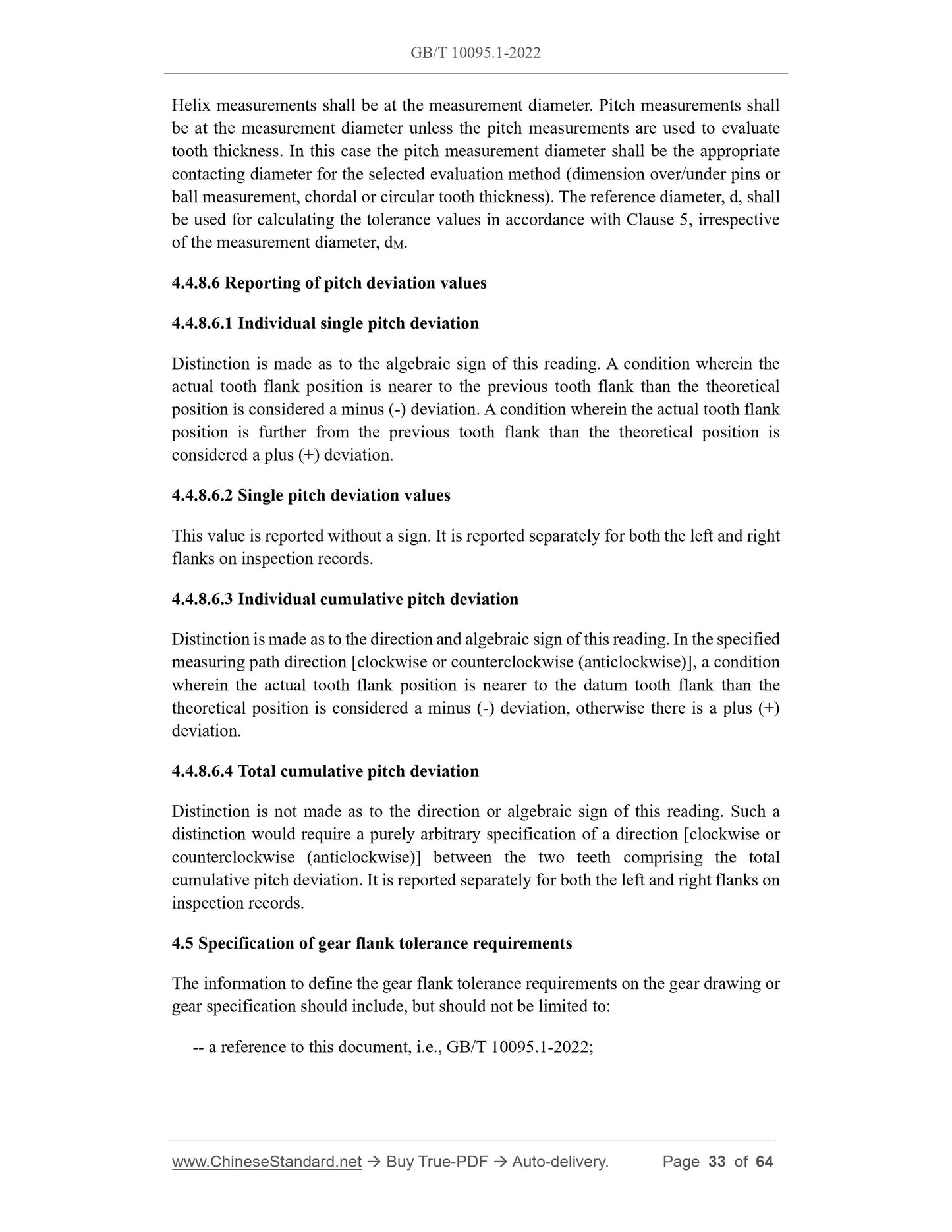
Helix measurements shall be at the measurement diameter. Pitch measurements shall
be at the measurement diameter unless the pitch measurements are used to evaluate
tooth thickness. In this case the pitch measurement diameter shall be the appropriate
contacting diameter for the selected evaluation method (dimension over/under pins or
ball measurement, chordal or circular tooth thickness). The reference diameter, d, shall
be used for calculating the tolerance values in accordance with Clause 5, irrespective
of the measurement diameter, dM.
4.4.8.6 Reporting of pitch deviation values
4.4.8.6.1 Individual single pitch deviation
Distinction is made as to the algebraic sign of this reading. A condition wherein the
actual tooth flank position is nearer to the previous tooth flank than the theoretical
position is considered a minus (-) deviation. A condition wherein the actual tooth flank
position is further from the previous tooth flank than the theoretical position is
considered a plus (+) deviation.
4.4.8.6.2 Single pitch deviation values
This value is reported without a sign. It is reported separately for both the left and right
flanks on inspection records.
4.4.8.6.3 Individual cumulative pitch deviation
Distinction is made as to the direction and algebraic sign of this reading. In the specified
measuring path direction [clockwise or counterclockwise (anticlockwise)], a condition
wherein the actual tooth flank position is nearer to the datum tooth flank than the
theoretical position is considered a minus (-) deviation, otherwise there is a plus (+)
deviation.
4.4.8.6.4 Total cumulative pitch deviation
Distinction is not made as to the direction or algebraic sign of this reading. Such a
distinction would require a purely arbitrary specification of a direction [clockwise or
counterclockwise (anticlockwise)] between the two teeth comprising the total
cumulative pitch deviation. It is reported separately for both the left and right flanks on
inspection records.
4.5 Specification of gear flank tolerance requirements
The information to define the gear flank tolerance requirements on the gear drawing or
gear specification should include, but should not be limited to:
-- a reference to this document, i.e., GB/T 10095.1-2022;
GB/T 10095.1-2022
GB
NATIONAL STANDARD OF THE
PEOPLE’S REPUBLIC OF CHINA
ICS 21.200
CCS J 17
GB/T 10095.1-2022 / ISO 1328-1:2013
Replacing GB/T 10095.1-2008
Cylindrical gears - ISO system of flank tolerance
classification - Part 1: Definitions and allowable values of
deviations relevant to flanks of gear teeth
(ISO 1328-1:2013, IDT)
ISSUED ON: OCTOBER 12, 2022
IMPLEMENTED ON: OCTOBER 12, 2022
Issued by: State Administration for Market Regulation;
Standardization Administration of the People’s Republic of China.
Table of Contents
Foreword ... 3
Introduction ... 5
1 Scope ... 6
2 Normative references ... 7
3 Terms, definitions and symbols ... 8
3.1 Fundamental terms and symbols ... 8
3.2 General dimensions ... 12
3.3 Pitch deviations ... 15
3.4 Profile deviations ... 16
3.5 Helix deviations ... 21
4 Application of the ISO flank tolerance classification system ... 25
4.1 General ... 25
4.2 Geometrical parameters to be verified ... 25
4.3 Equipment verification and uncertainty ... 27
4.4 Considerations for elemental measurements ... 27
4.5 Specification of gear flank tolerance requirements ... 33
4.6 Acceptance and evaluation criteria ... 34
4.7 Presentation of data ... 35
5 Tolerance values ... 35
5.1 General ... 35
5.2 Use of formulae ... 36
5.3 Tolerance formulae ... 36
Annex A (Normative) Zone-based tolerance evaluation ... 39
Annex B (Normative) Evaluation of profile and helix deviations using the second order
analysis method ... 43
Annex C (Informative) Profile and helix data filtering ... 47
Annex D (Informative) Sector pitch deviation ... 49
Annex E (Normative) Allowable values of runout ... 53
Annex F (Informative) Single flank composite testing ... 56
Annex G (Informative) Adjacent pitch difference, fu ... 62
Bibliography ... 64
Foreword
This document was drafted in accordance with the rules provided in GB/T 1.1-2020
Directives for Standardization - Part 1: Rules for the Structure and Drafting of
Standardizing Documents.
This document is Part 1 of GB/T 10095 Cylindrical gears - ISO system of flank
tolerance classification. The following parts have been issued for GB/T 10095:
-- Part 1: Definitions and allowable values of deviations relevant to flanks of gear
teeth;
-- Part 2: Definitions and allowable values of deviations relevant to radial composite
deviations and runout information.
This document replaces GB/T 10095.1-2008, Cylindrical gears - System of accuracy -
Part 1: Definitions and allowable values of deviations relevant to corresponding flanks
of gear teeth. Compared with GB/T 10095.1-2008, in addition to structural adjustments
and editorial changes, the main technical changes of this document are as follows:
a) Change the scope of application (see Clause 1; Clause 1 of the 2008 edition);
b) Change the formulae for calculating the flank tolerance (see 5.3; Clause 6 of the
2008 edition);
c) Add the analysis method of modified profile and helix (see Annex A and Annex
B);
d) Add the calculation of the allowable values of runout (see Annex E).
This document is identical to ISO 1328-1:2013 Cylindrical gears - ISO system of flank
tolerance classification - Part 1: Definitions and allowable values of deviations
relevant to flanks of gear teeth.
Please note that some of the contents of this document may involve patents. The issuing
organization of this document is not responsible for identifying patents.
This document shall be under the jurisdiction of National Technical Committee 52 on
Gear of Standardization Administration of China (SAC/TC 52).
Drafting organizations of this document: Zhengzhou Research Institute of Mechanical
Engineering Co., Ltd., Beijing University of Technology, Ningbo ZD Leader
Transmission Equipment Co., Ltd., Zhejiang Shuanghuan Driveline Co., Ltd., Nanjing
High Speed and Accurate Gear (Group) Co., Ltd., Shaanxi Faster Automotive Drive
Group Co., Ltd., Jiangsu Guomao Reducer Co., Ltd., Zhejiang Fore Intelligent
Technology Co., Ltd., Shenzhen Zhaowei Machinery and Electronic Co., Ltd., Ningbo
Cylindrical gears - ISO system of flank tolerance
classification - Part 1: Definitions and allowable values of
de...
Share
