NaN
/
of
-Infinity
www.ChineseStandard.us -- Field Test Asia Pte. Ltd.
GB/T 1032-2023 English PDF (GB/T1032-2023)
GB/T 1032-2023 English PDF (GB/T1032-2023)
Regular price
$1,175.00
Regular price
Sale price
$1,175.00
Unit price
/
per
Shipping calculated at checkout.
Couldn't load pickup availability
GB/T 1032-2023: Test methods for three-phase asynchronous motors
Delivery: 9 seconds. Download (& Email) true-PDF + Invoice.
Get Quotation: Click GB/T 1032-2023 (Self-service in 1-minute)
Historical versions (Master-website): GB/T 1032-2023
Preview True-PDF (Reload/Scroll-down if blank)
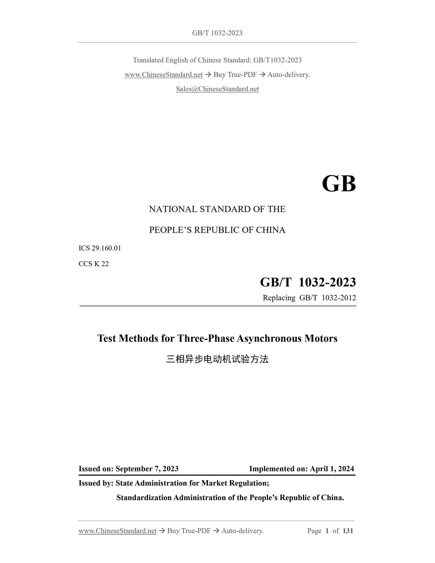
GB/T 1032-2023
GB
NATIONAL STANDARD OF THE
PEOPLE’S REPUBLIC OF CHINA
ICS 29.160.01
CCS K 22
Replacing GB/T 1032-2012
Test Methods for Three-Phase Asynchronous Motors
ISSUED ON: SEPTEMBER 7, 2023
IMPLEMENTED ON: APRIL 1, 2024
Issued by: State Administration for Market Regulation;
Standardization Administration of the People’s Republic of China.
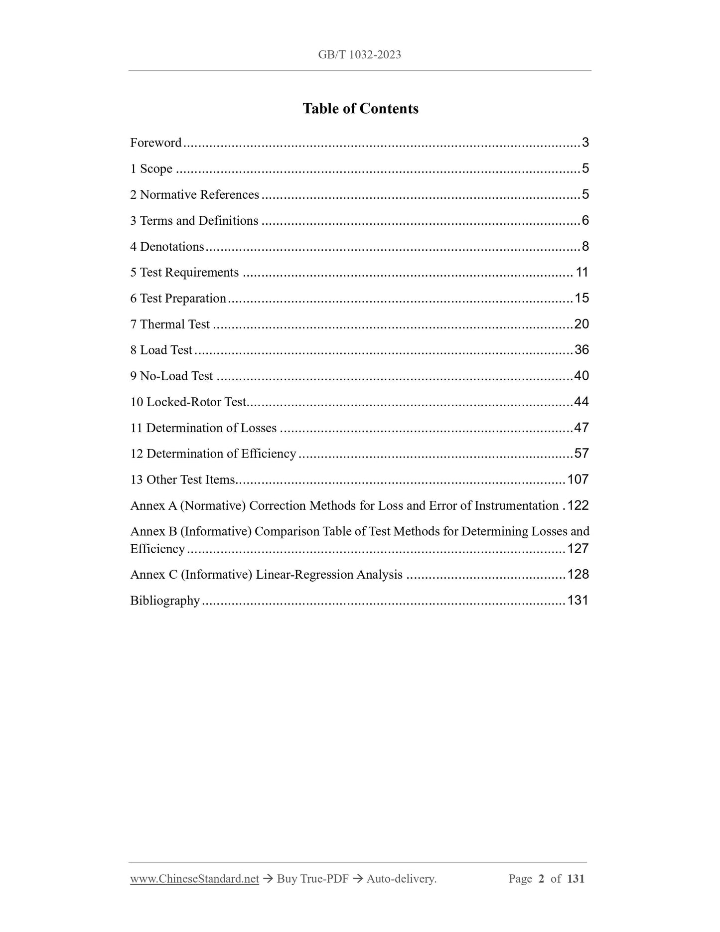
Table of Contents
Foreword ... 3
1 Scope ... 5
2 Normative References ... 5
3 Terms and Definitions ... 6
4 Denotations ... 8
5 Test Requirements ... 11
6 Test Preparation ... 15
7 Thermal Test ... 20
8 Load Test ... 36
9 No-Load Test ... 40
10 Locked-Rotor Test... 44
11 Determination of Losses ... 47
12 Determination of Efficiency ... 57
13 Other Test Items ... 107
Annex A (Normative) Correction Methods for Loss and Error of Instrumentation . 122
Annex B (Informative) Comparison Table of Test Methods for Determining Losses and
Efficiency ... 127
Annex C (Informative) Linear-Regression Analysis ... 128
Bibliography ... 131
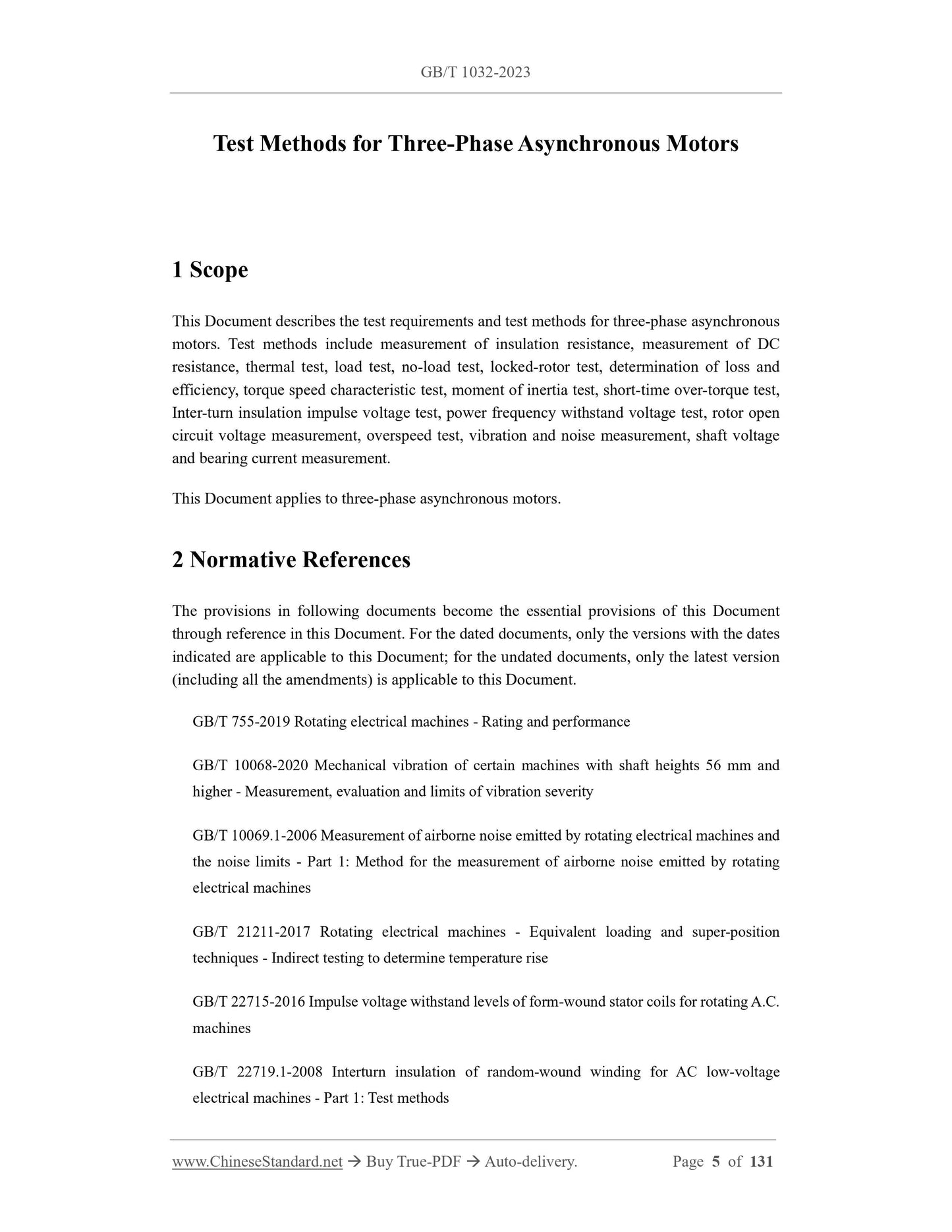
Test Methods for Three-Phase Asynchronous Motors
1 Scope
This Document describes the test requirements and test methods for three-phase asynchronous
motors. Test methods include measurement of insulation resistance, measurement of DC
resistance, thermal test, load test, no-load test, locked-rotor test, determination of loss and
efficiency, torque speed characteristic test, moment of inertia test, short-time over-torque test,
Inter-turn insulation impulse voltage test, power frequency withstand voltage test, rotor open
circuit voltage measurement, overspeed test, vibration and noise measurement, shaft voltage
and bearing current measurement.
This Document applies to three-phase asynchronous motors.
2 Normative References
The provisions in following documents become the essential provisions of this Document
through reference in this Document. For the dated documents, only the versions with the dates
indicated are applicable to this Document; for the undated documents, only the latest version
(including all the amendments) is applicable to this Document.
GB/T 755-2019 Rotating electrical machines - Rating and performance
GB/T 10068-2020 Mechanical vibration of certain machines with shaft heights 56 mm and
higher - Measurement, evaluation and limits of vibration severity
GB/T 10069.1-2006 Measurement of airborne noise emitted by rotating electrical machines and
the noise limits - Part 1: Method for the measurement of airborne noise emitted by rotating
electrical machines
GB/T 21211-2017 Rotating electrical machines - Equivalent loading and super-position
techniques - Indirect testing to determine temperature rise
GB/T 22715-2016 Impulse voltage withstand levels of form-wound stator coils for rotating A.C.
machines
GB/T 22719.1-2008 Interturn insulation of random-wound winding for AC low-voltage
electrical machines - Part 1: Test methods
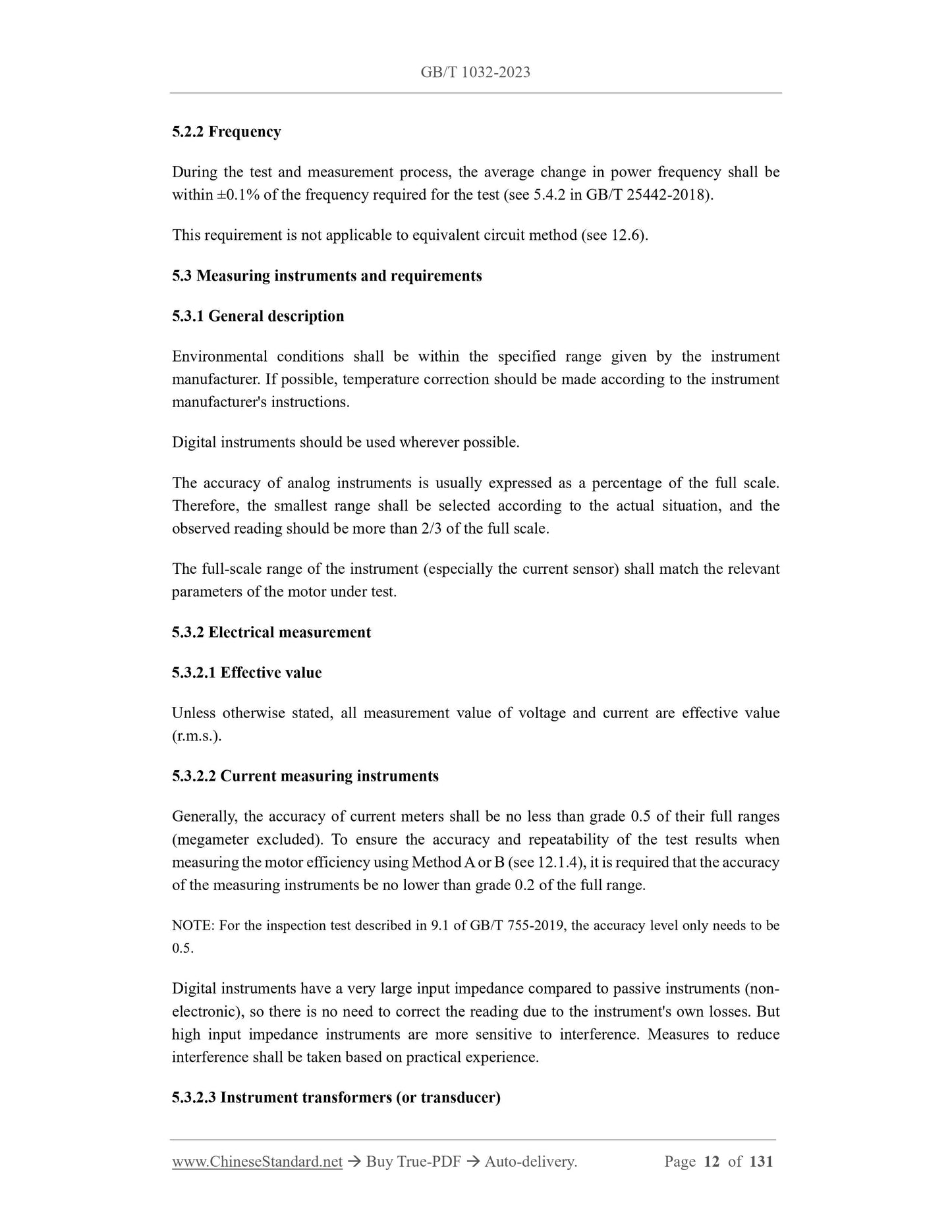
5.2.2 Frequency
During the test and measurement process, the average change in power frequency shall be
within ±0.1% of the frequency required for the test (see 5.4.2 in GB/T 25442-2018).
This requirement is not applicable to equivalent circuit method (see 12.6).
5.3 Measuring instruments and requirements
5.3.1 General description
Environmental conditions shall be within the specified range given by the instrument
manufacturer. If possible, temperature correction should be made according to the instrument
manufacturer's instructions.
Digital instruments should be used wherever possible.
The accuracy of analog instruments is usually expressed as a percentage of the full scale.
Therefore, the smallest range shall be selected according to the actual situation, and the
observed reading should be more than 2/3 of the full scale.
The full-scale range of the instrument (especially the current sensor) shall match the relevant
parameters of the motor under test.
5.3.2 Electrical measurement
5.3.2.1 Effective value
Unless otherwise stated, all measurement value of voltage and current are effective value
(r.m.s.).
5.3.2.2 Current measuring instruments
Generally, the accuracy of current meters shall be no less than grade 0.5 of their full ranges
(megameter excluded). To ensure the accuracy and repeatability of the test results when
measuring the motor efficiency using Method A or B (see 12.1.4), it is required that the accuracy
of the measuring instruments be no lower than grade 0.2 of the full range.
NOTE: For the inspection test described in 9.1 of GB/T 755-2019, the accuracy level only needs to be
0.5.
Digital instruments have a very large input impedance compared to passive instruments (non-
electronic), so there is no need to correct the reading due to the instrument's own losses. But
high input impedance instruments are more sensitive to interference. Measures to reduce
interference shall be taken based on practical experience.
5.3.2.3 Instrument transformers (or transducer)
The accuracy level of the instrument transformer (or transducer) used for measurement shall be
no lower than 0.2. When using method B to determine motor efficiency, if the transformer or
transducer and the instrument measuring voltage, current or power are calibrated as a system,
the error of the system shall not exceed ±0.2% of the full scale.
5.3.2.4 Voltage measurement
The signal wire used to measure the terminal voltage shall be connected with the motor terminal.
If this is not allowed on the site, it is required to calculate the corresponding error and correct
the readings. Arithmetic mean of the three phase voltages (Uuv, Uvw, Uwu) shall be used to obtain
the motor performance.
5.3.2.5 Current measurement
Each of the three line-currents of electric motors shall be measured concurrently. Arithmetic
mean of the three phase currents shall be used to obtain the motor performance.
When using current transformer (or transducer), the total impedance of the instruments
connected with secondary circuit (including connecting wires) shall be no larger than the rated
values.
For electric motors with IN < 5 A, current transformer (or transducer) shall not be used except
for the locked rotor test and overload test.
5.3.2.6 Power measurement
Two-meter method (2 single-phase power meters) shall be used to measure the input power of
3-phase motors. Alternatively, 1 set of 3-phase power meter or 3 sets of single-phase power
meters could be used to measure the input power. The voltage signal line of the power meter
shall be connected to the winding lead terminal.
If the instrumental loss may affect the accuracy of test data, please correct the instrumental loss
and the error thereof in accordance with Annex A.
5.3.3 Resistance measurement
The winding D.C. resistance shall be measured using electric bridge or digital micro-ohmmeter,
of which the accuracy shall be no less than grade 0.2.
5.3.4 Frequency measurement
Accuracy of frequency meter shall be no less than grade 0.1.
5.3.5 Measurement of rotating speed or slip
5.3.5.1 Rotation speed measurement
temperature (measured with a thermal meter or embedded temperature detector) and the
temperature of cooling agent shall not exceed 2K. For large- and medium-scale motors, the
keeping time of thermal meters shall be no less than 15 min.
For motors practicing a short working system (S2 working shift), the difference between the
winding temperature and the temperature of cooling agent, at the beginning of testing, shall be
within 5K.
6.2.2 Measurement of Winding D.C. end resistance
6.2.2.1 General
D.C. resistance between winding terminals U and V, V and W, W and U is named as end-
resistance, which can be separately marked as RUV, RVW and RWU. Winding DC end-resistance
can be measured by bridge method, micro-ohmmeter method, DC voltmeter-ammeter method,
etc.
6.2.2.2 Bridge Method
Each resistance shall be measured for 3 times, each of which shall be measured and read for
number after rebalance of electric bridge when using electric bridge for measuring. Difference
between each reading and the arithmetic mean value of 3 times of reading shall be no larger
than ±0.5% of the mean value, and the mean value shall be taken as the actual value of the
resistance.
If end-resistance of winding is lower than 1 Ω, Kelvin [double-arm] bridge shall be adopted for
measuring.
6.2.2.3 Micro-ohmmeter Method
When the winding end-resistance is measured with instruments such as automatic monitoring
device or digital micro-ohmmeter, the test current of measured winding shall be no more than
10% of the current during its normal operation, and the conduction time shall be within 1 min.
In case that the resistance is less than 0.01 Ω, it is not suitable that the current of winding
measured is too low.
6.2.2.4 DC Voltmeter-Ammeter Method
The principle wiring diagram of the voltmeter-ammeter method is shown in Figure 2. Among
them, Rb is the adjusting current limiting resistance, R is the measured winding end resistance,
V is the voltmeter, and A is the ammeter. Figure 2a) is applicable to the situation where the ratio
of the internal resistance of the voltmeter to the resistance being measured is greater than 200;
Figure 2b) is applicable to the situation where the ratio of the internal resistance of the ammeter
to the resistance being measured is less than 1/200.
During measurement, the applied current shall be no more than 10% of the rated winding
At the beginning of the thermal test, all temperature measuring devices shall be checked to
ensure that they do not increase the temperature measurement error due to the influence of stray
magnetic fields.
The temperature of the fully enclosed motor rotor and other parts can be quickly measured with
a temperature measuring device after the power is shut down.
7.3 Measurement method of temperature
7.3.1 General
There are three methods of temperature measurement:
--- Resistance method;
--- Embedded thermometer method;
---Thermometer method.
Different methods shall not be used for cross-checking.
The indirect measurement method is in accordance with the provisions of GB/T 21211-2017.
7.3.2 Resistance method
The temperature of the winding is determined based on the increase in winding resistance.
The measurement methods are as follows:
--- Use a bridge or micro-ohmmeter of appropriate range and measure directly at the
beginning and end of the test, see 6.2.2.2 and 6.2.2.3;
--- Measured with a D.C. ammeter-voltmeter, see 6.2.2.4;
--- Live measurement method, without interrupting the A.C. load current, superimposes a
weak D.C. measurement current on the load current, see 8.6.2.1 in GB/T 755-2019.
Small errors in the winding resistance will cause large errors when determining the temperature.
Therefore, special attention shall be paid to this measurement to ensure that the accurate
resistance value is measured.
7.3.3 Embedded thermometer method
Use a thermometer embedded inside the motor (such as a resistance thermometer, thermocouple
or semiconductor negative temperature coefficient thermometer) to measure the temperature.
The thermometer is embedded in an out-of-reach part of the motor during the manufacturing
process.
7.3.4 Thermometer method
Measure the temperature by attaching a thermometer to an accessible surface of the motor. The
term "thermometer" includes not only expansion thermometers, but also non-embedded
thermocouples and resistance thermometers. When the expansion thermometer is used to
measure the temperature of a location with a strong alternating or moving magnetic field, an
alcohol thermometer shall be used instead of a mercury thermometer.
7.4 Measurement of cooling agent temperature
7.4.1 Reference cooling medium
The determination of reference cooling medium of the motor shall be as specified in Table 5 of
GB/T 755-2019.
7.4.2 Air-cooled motor
For motors cooled by ambient air, multi-point measurements (2 to 3 points) shall be made on
the path where the cooling air enters the motor. The measuring point is placed about 1m~2m
away from the motor, at half the height of the motor, and shall be protected from the influence
of external heat radiation and air flow.
7.4.3 External cooler motor
For motors that use external coolers and pipe ventilation cooling, the temperature of the cooling
medium shall be measured at the entrance of the cooling medium into the motor.
7.4.4 Internal cooler motor
For motors cooled that use an internal cooler, the temperature of the cooling medium shall be
measured at the outlet of the cooler; for motors with a liquid (usually water) cooler, the
temperature of the coolant shall be measured at the inlet of the cooler.
7.4.5 Determination of the cooling medium temperature at the end of the test
7.4.5.1 Continuous working system (S1) and intermittent periodic working system (S3)
motors
For continuous working system (S1) and intermittent periodic working system (S3) motors, the
cooling medium temperature at the end of the test shall take the average value of the
thermometer reading measured at the same time interval during the last 1/4 of the entire test
process.
7.4.5.2 Short-time working system (S2) motor
For the cooling medium temperature at the end of the short-time working system (S2) motor
test, if the rating is 30min and below, take the average value of the thermometer readings at the
temperature readings shall be regarded as the ring temperature.
7.6 Thermal test methods
7.6.1 General
Thermal test methods consist of direct method and indirect method, and the former method is
generally preferred, indirect method for continuous rating motor only.
Indirect method includes reduced voltage load method, reduced current load method, and stator
frequency method as well as other indirect methods specified in GB/T 21211-2017.
7.6.2 Direct method
7.6.2.1 General
Thermal test by direct method shall be conducted at the rated frequency, rated voltage, and rated
load or nominal current.
7.6.2.2 Continuous rating motors (S1)
The thermal test of continuous operating (S...


