1
/
of
11
PayPal, credit cards. Download editable-PDF and invoice in 1 second!
GB/T 1038.2-2022 English PDF (GBT1038.2-2022)
GB/T 1038.2-2022 English PDF (GBT1038.2-2022)
Regular price
$260.00 USD
Regular price
Sale price
$260.00 USD
Unit price
/
per
Shipping calculated at checkout.
Couldn't load pickup availability
Delivery: 3 seconds. Download true-PDF + Invoice.
Get QUOTATION in 1-minute: Click GB/T 1038.2-2022
Historical versions: GB/T 1038.2-2022
Preview True-PDF (Reload/Scroll if blank)
GB/T 1038.2-2022: Plastics -- Film and sheeting -- Determination of gas-transmission rate -- Part 2: Equal-pressure methods
GB/T 1038.2-2022
GB
NATIONAL STANDARD OF THE
PEOPLE’S REPUBLIC OF CHINA
ICS 83.140.10
CCS G 31
Plastics - Film and Sheeting - Determination of Gas-
transmission Rate - Part 2: Equal-pressure Methods
(ISO 15105-2:2003, MOD)
ISSUED ON: OCTOBER 12, 2022
IMPLEMENTED ON: MAY 1, 2023
Issued by: State Administration for Market Regulation;
Standardization Administration of the People’s Republic of China.
Table of Contents
Foreword ... 3
Introduction ... 5
1 Scope ... 6
2 Normative References ... 6
3 Terms and Definitions ... 6
4 Principle ... 7
5 Specimen ... 7
6 Conditioning and Test Temperature ... 7
7 Instruments and Equipment ... 8
8 Diffusion Conditions ... 9
9 Test Procedures ... 10
10 Expression of Test Results ... 10
11 Precision ... 10
12 Test Report ... 10
Appendix A (normative) Coulomb Sensor Method ... 11
Appendix B (normative) Gas Chromatography ... 16
Plastics - Film and Sheeting - Determination of Gas-
transmission Rate - Part 2: Equal-pressure Methods
1 Scope
This document specifies two test methods for the gas transmission of plastic film and sheeting,
co-extrusion material, plastic coating material and laminated board under the condition of equal
pressure---coulomb sensor method and gas chromatography.
This document is applicable to the determination of gas transmission of plastic film and
sheeting. The determination of gas transmission of other materials may take this as a reference.
2 Normative References
The contents of the following documents constitute indispensable clauses of this document
through the normative references in this text. In terms of references with a specified date, only
versions with a specified date are applicable to this document. In terms of references without a
specified date, the latest version (including all the modifications) is applicable to this document.
GB/T 6672 Plastics Film and Sheeting - Determination of Thickness by Mechanical Scanning
(GB/T 6672-2001, ISO 4593:1993, IDT)
3 Terms and Definitions
The following terms and definitions are applicable to this document.
3.1 Gas Transmission Rate; GTR
Gas transmission rate refers to the amount of gas permeating through a unit area of the material
per unit time under the unit partial pressure difference on both sides of the plastic material.
NOTE 1: when the test gas is oxygen, the test result is oxygen transmission rate (O2GTR).
NOTE 2: when it is expressed by the amount of substance, the unit is [mol/(m2 s Pa)]; when it
is expressed by volume, the unit is [cm3/(m2 d Pa)].
3.2 Gas Permeability; Coefficient of Gas Permeability
Gas permeability / coefficient of gas permeability refers to the amount of gas permeated per
unit area and unit thickness of the material per unit time under the unit partial pressure
difference on both sides of the plastic material.
NOTE 1: when it is expressed by the amount of substance, the unit is [mol m/(m2 s Pa)]; when
it is expressed by volume, the unit is [cm3 cm/(cm2 s Pa)].
NOTE 2: although P is a physical property of the polymer, the film preparation method affects the
orientation and crystal structure of the polymer material, which in turn affects the
permeability of the material.
NOTE 3: P is only used to measure single-layer plastic film and sheeting made of a single material.
4 Principle
The specimen clamped in the permeation chamber (see Figure A.1 and Figure B.1) divides the
permeation chamber into two mutually independent parts (Chamber A and Chamber B). The
test gas is introduced into Chamber A, while the carrier gas is introduced into Chamber B for
slow purge. The total pressure in each chamber is equal (ambient atmospheric pressure). Due
to the relatively high partial pressure of the test gas in Chamber A, the test gas permeates
through the specimen into Chamber B, and is carried to the sensor by the carrier gas.
The type of sensor used depends on the specimen material and the test gas.
5 Specimen
5.1 The specimen shall be representative, free of defects like wrinkles, folds and pinholes, and
uniform in thickness. The area of the specimen shall be larger than the gas permeation area of
the permeation chamber, and shall be tightly clamped on the permeation chamber.
5.2 Unless it is otherwise specified or agreed upon by the relevant parties, three specimens shall
be tested.
5.3 Mark the surface of the specimen facing the test gas.
NOTE: in principle, it is recommended that the test shall be exactly the same as the actual use
conditions, for example, for packaging materials, the gas permeates from the inside to the
outside, or from the outside to the inside.
5.4 In accordance with GB/T 6672, measure the thickness of each specimen, expressed in (m).
On the entire test area, measure no less than 5 points; record the minimum, maximum and
average values, and the results are accurate to 1 m.
6 Conditioning and Test Temperature
6.1 Conditioning
The specimen shall:
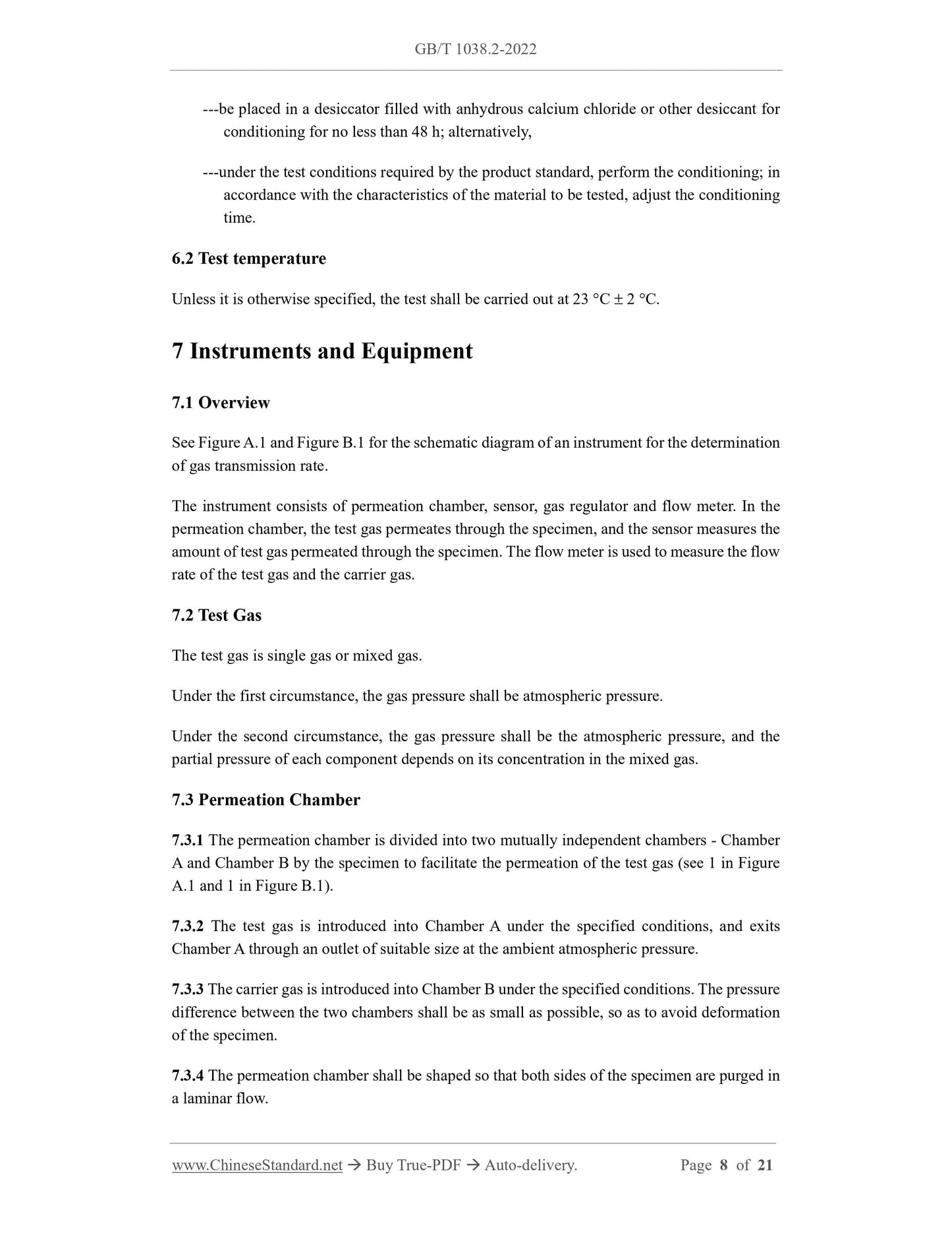
---be placed in a desiccator filled with anhydrous calcium chloride or other desiccant for
conditioning for no less than 48 h; alternatively,
---under the test conditions required by the product standard, perform the conditioning; in
accordance with the characteristics of the material to be tested, adjust the conditioning
time.
6.2 Test temperature
Unless it is otherwise specified, the test shall be carried out at 23 C 2 C.
7 Instruments and Equipment
7.1 Overview
See Figure A.1 and Figure B.1 for the schematic diagram of an instrument for the determination
of gas transmission rate.
The instrument consists of permeation chamber, sensor, gas regulator and flow meter. In the
permeation chamber, the test gas permeates through the specimen, and the sensor measures the
amount of test gas permeated through the specimen. The flow meter is used to measure the flow
rate of the test gas and the carrier gas.
7.2 Test Gas
The test gas is single gas or mixed gas.
Under the first circumstance, the gas pressure shall be atmospheric pressure.
Under the second circumstance, the gas pressure shall be the atmospheric pressure, and the
partial pressure of each component depends on its concentration in the mixed gas.
7.3 Permeation Chamber
7.3.1 The permeation chamber is divided into two mutually independent chambers - Chamber
A and Chamber B by the specimen to facilitate the permeation of the test gas (see 1 in Figure
A.1 and 1 in Figure B.1).
7.3.2 The test gas is introduced into Chamber A under the specified conditions, and exits
Chamber A through an outlet of suitable size at the ambient atmospheric pressure.
7.3.3 The carrier gas is introduced into Chamber B under the specified conditions. The pressure
difference between the two chambers shall be as small as possible, so as to avoid deformation
of the specimen.
7.3.4 The permeation chamber shall be shaped so that both sides of the specimen are purged in
a laminar flow.
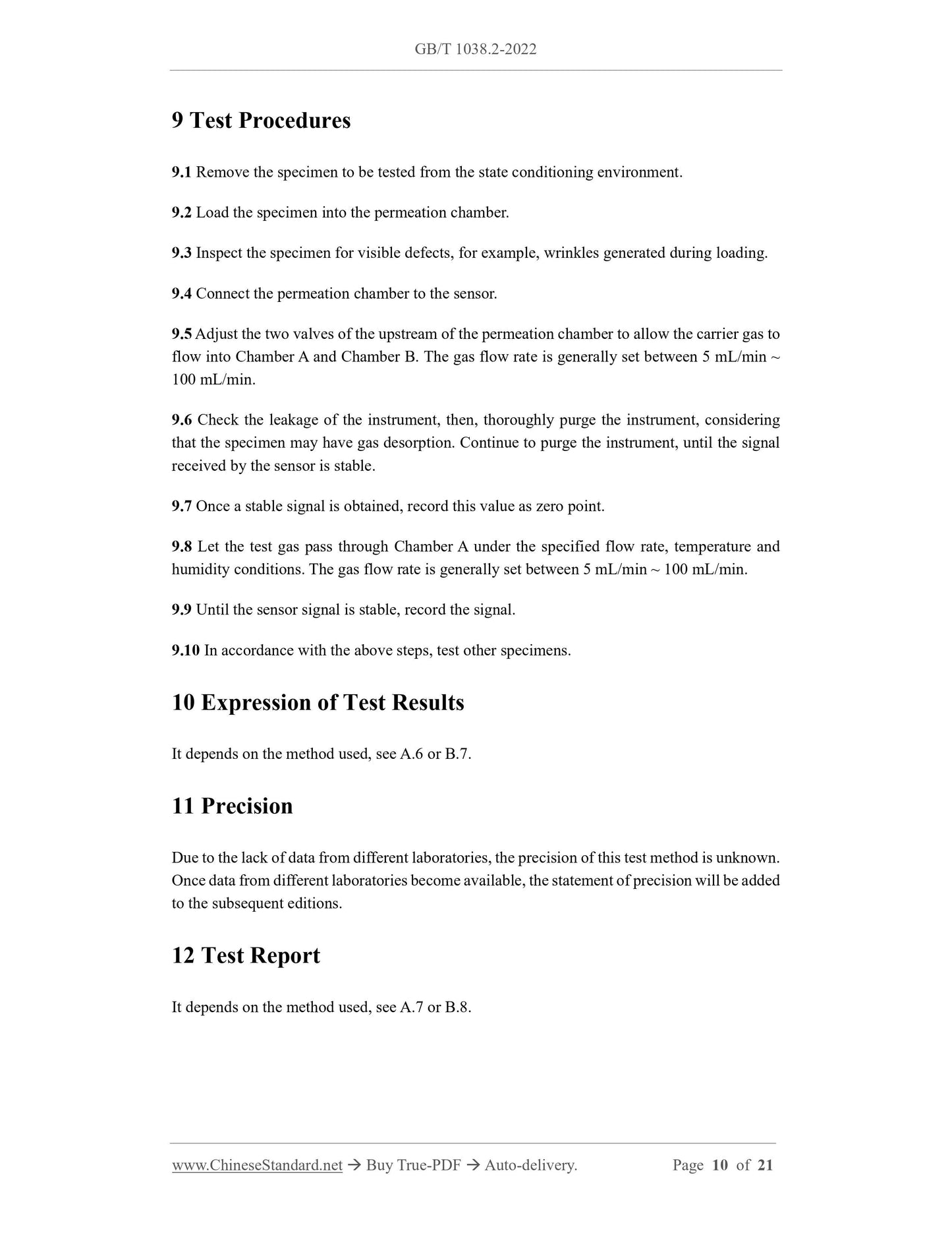
9 Test Procedures
9.1 Remove the specimen to be tested from the state conditioning environment.
9.2 Load the specimen into the permeation chamber.
9.3 Inspect the specimen for visible defects, for example, wrinkles generated during loading.
9.4 Connect the permeation chamber to the sensor.
9.5 Adjust the two valves of the upstream of the permeation chamber to allow the carrier gas to
flow into Chamber A and Chamber B. The gas flow rate is generally set between 5 mL/min ~
100 mL/min.
9.6 Check the leakage of the instrument, ...
Get QUOTATION in 1-minute: Click GB/T 1038.2-2022
Historical versions: GB/T 1038.2-2022
Preview True-PDF (Reload/Scroll if blank)
GB/T 1038.2-2022: Plastics -- Film and sheeting -- Determination of gas-transmission rate -- Part 2: Equal-pressure methods
GB/T 1038.2-2022
GB
NATIONAL STANDARD OF THE
PEOPLE’S REPUBLIC OF CHINA
ICS 83.140.10
CCS G 31
Plastics - Film and Sheeting - Determination of Gas-
transmission Rate - Part 2: Equal-pressure Methods
(ISO 15105-2:2003, MOD)
ISSUED ON: OCTOBER 12, 2022
IMPLEMENTED ON: MAY 1, 2023
Issued by: State Administration for Market Regulation;
Standardization Administration of the People’s Republic of China.
Table of Contents
Foreword ... 3
Introduction ... 5
1 Scope ... 6
2 Normative References ... 6
3 Terms and Definitions ... 6
4 Principle ... 7
5 Specimen ... 7
6 Conditioning and Test Temperature ... 7
7 Instruments and Equipment ... 8
8 Diffusion Conditions ... 9
9 Test Procedures ... 10
10 Expression of Test Results ... 10
11 Precision ... 10
12 Test Report ... 10
Appendix A (normative) Coulomb Sensor Method ... 11
Appendix B (normative) Gas Chromatography ... 16
Plastics - Film and Sheeting - Determination of Gas-
transmission Rate - Part 2: Equal-pressure Methods
1 Scope
This document specifies two test methods for the gas transmission of plastic film and sheeting,
co-extrusion material, plastic coating material and laminated board under the condition of equal
pressure---coulomb sensor method and gas chromatography.
This document is applicable to the determination of gas transmission of plastic film and
sheeting. The determination of gas transmission of other materials may take this as a reference.
2 Normative References
The contents of the following documents constitute indispensable clauses of this document
through the normative references in this text. In terms of references with a specified date, only
versions with a specified date are applicable to this document. In terms of references without a
specified date, the latest version (including all the modifications) is applicable to this document.
GB/T 6672 Plastics Film and Sheeting - Determination of Thickness by Mechanical Scanning
(GB/T 6672-2001, ISO 4593:1993, IDT)
3 Terms and Definitions
The following terms and definitions are applicable to this document.
3.1 Gas Transmission Rate; GTR
Gas transmission rate refers to the amount of gas permeating through a unit area of the material
per unit time under the unit partial pressure difference on both sides of the plastic material.
NOTE 1: when the test gas is oxygen, the test result is oxygen transmission rate (O2GTR).
NOTE 2: when it is expressed by the amount of substance, the unit is [mol/(m2 s Pa)]; when it
is expressed by volume, the unit is [cm3/(m2 d Pa)].
3.2 Gas Permeability; Coefficient of Gas Permeability
Gas permeability / coefficient of gas permeability refers to the amount of gas permeated per
unit area and unit thickness of the material per unit time under the unit partial pressure
difference on both sides of the plastic material.
NOTE 1: when it is expressed by the amount of substance, the unit is [mol m/(m2 s Pa)]; when
it is expressed by volume, the unit is [cm3 cm/(cm2 s Pa)].
NOTE 2: although P is a physical property of the polymer, the film preparation method affects the
orientation and crystal structure of the polymer material, which in turn affects the
permeability of the material.
NOTE 3: P is only used to measure single-layer plastic film and sheeting made of a single material.
4 Principle
The specimen clamped in the permeation chamber (see Figure A.1 and Figure B.1) divides the
permeation chamber into two mutually independent parts (Chamber A and Chamber B). The
test gas is introduced into Chamber A, while the carrier gas is introduced into Chamber B for
slow purge. The total pressure in each chamber is equal (ambient atmospheric pressure). Due
to the relatively high partial pressure of the test gas in Chamber A, the test gas permeates
through the specimen into Chamber B, and is carried to the sensor by the carrier gas.
The type of sensor used depends on the specimen material and the test gas.
5 Specimen
5.1 The specimen shall be representative, free of defects like wrinkles, folds and pinholes, and
uniform in thickness. The area of the specimen shall be larger than the gas permeation area of
the permeation chamber, and shall be tightly clamped on the permeation chamber.
5.2 Unless it is otherwise specified or agreed upon by the relevant parties, three specimens shall
be tested.
5.3 Mark the surface of the specimen facing the test gas.
NOTE: in principle, it is recommended that the test shall be exactly the same as the actual use
conditions, for example, for packaging materials, the gas permeates from the inside to the
outside, or from the outside to the inside.
5.4 In accordance with GB/T 6672, measure the thickness of each specimen, expressed in (m).
On the entire test area, measure no less than 5 points; record the minimum, maximum and
average values, and the results are accurate to 1 m.
6 Conditioning and Test Temperature
6.1 Conditioning
The specimen shall:
---be placed in a desiccator filled with anhydrous calcium chloride or other desiccant for
conditioning for no less than 48 h; alternatively,
---under the test conditions required by the product standard, perform the conditioning; in
accordance with the characteristics of the material to be tested, adjust the conditioning
time.
6.2 Test temperature
Unless it is otherwise specified, the test shall be carried out at 23 C 2 C.
7 Instruments and Equipment
7.1 Overview
See Figure A.1 and Figure B.1 for the schematic diagram of an instrument for the determination
of gas transmission rate.
The instrument consists of permeation chamber, sensor, gas regulator and flow meter. In the
permeation chamber, the test gas permeates through the specimen, and the sensor measures the
amount of test gas permeated through the specimen. The flow meter is used to measure the flow
rate of the test gas and the carrier gas.
7.2 Test Gas
The test gas is single gas or mixed gas.
Under the first circumstance, the gas pressure shall be atmospheric pressure.
Under the second circumstance, the gas pressure shall be the atmospheric pressure, and the
partial pressure of each component depends on its concentration in the mixed gas.
7.3 Permeation Chamber
7.3.1 The permeation chamber is divided into two mutually independent chambers - Chamber
A and Chamber B by the specimen to facilitate the permeation of the test gas (see 1 in Figure
A.1 and 1 in Figure B.1).
7.3.2 The test gas is introduced into Chamber A under the specified conditions, and exits
Chamber A through an outlet of suitable size at the ambient atmospheric pressure.
7.3.3 The carrier gas is introduced into Chamber B under the specified conditions. The pressure
difference between the two chambers shall be as small as possible, so as to avoid deformation
of the specimen.
7.3.4 The permeation chamber shall be shaped so that both sides of the specimen are purged in
a laminar flow.
9 Test Procedures
9.1 Remove the specimen to be tested from the state conditioning environment.
9.2 Load the specimen into the permeation chamber.
9.3 Inspect the specimen for visible defects, for example, wrinkles generated during loading.
9.4 Connect the permeation chamber to the sensor.
9.5 Adjust the two valves of the upstream of the permeation chamber to allow the carrier gas to
flow into Chamber A and Chamber B. The gas flow rate is generally set between 5 mL/min ~
100 mL/min.
9.6 Check the leakage of the instrument, ...
Share