1
/
of
10
www.ChineseStandard.us -- Field Test Asia Pte. Ltd.
GB/T 11344-2021 English PDF (GB/T11344-2021)
GB/T 11344-2021 English PDF (GB/T11344-2021)
Regular price
$470.00
Regular price
Sale price
$470.00
Unit price
/
per
Shipping calculated at checkout.
Couldn't load pickup availability
GB/T 11344-2021: Non-destructive testing - Ultrasonic thickness measurement
Delivery: 9 seconds. Download (& Email) true-PDF + Invoice.
Get Quotation: Click GB/T 11344-2021 (Self-service in 1-minute)
Historical versions (Master-website): GB/T 11344-2021
Preview True-PDF (Reload/Scroll-down if blank)
GB/T 11344-2021
GB
NATIONAL STANDARD OF THE
PEOPLE’S REPUBLIC OF CHINA
ICS 19.100
CCS J 04
Replacing GB/T 11344-2008
Non-destructive Testing - Ultrasonic Thickness
Measurement
(ISO 16809:2017, NEQ)
ISSUED ON: MAY 21, 2021
IMPLEMENTED ON: DECEMBER 1, 2021
Issued by: State Administration for Market Regulation;
Standardization Administration of the People’s Republic of
China.
Table of Contents
Foreword ... 3
1 Scope ... 5
2 Normative References ... 5
3 Terms and Definitions... 5
4 Method Summary ... 5
5 General Requirements ... 8
6 Measurement Preparation ... 10
7 Instrument Settings ... 14
8 Testing Reports and Records ... 17
Appendix A (informative) Ultrasonic Sound Velocity of Common Engineering
Application Materials ... 19
Appendix B (informative) Ultrasonic Thickness Measurement of Corrosion of
Vessels and Pipelines ... 22
Appendix C (informative) Selection of Measurement Method ... 29
Appendix D (informative) Factors Affecting Measurement Accuracy ... 33
Appendix E (informative) Instrument Settings under Special Testing Conditions
... 44
Bibliography ... 46
Non-destructive Testing - Ultrasonic Thickness
Measurement
1 Scope
This Standard specifies the ultrasonic thickness measurement through the ultrasonic
pulse-echo contact method.
This Standard is applicable to the ultrasonic thickness measurement of metal and non-
metal materials.
2 Normative References
The contents of the following documents constitute the indispensable clauses of this
document through the normative references. In terms of references with a specified
date, only versions with a specified date are applicable to this document. In terms of
references without a specified date, the latest version (including all the modifications)
is applicable to this document.
GB/T 9445 Non-destructive Testing - Qualification and Certification of NDT Personnel
(GB/T 9445-2015, ISO 9712:2012, IDT)
GB/T 12604.1 Non-destructive Testing - Terminology - Ultrasonic Testing (GB/T
12604.1-2020, ISO 5577:2017, MOD)
GB/T 20737 Non-destructive Testing - General Terms and Definitions (GB/T 20737-
2006, ISO/TS 18173:2005, IDT)
GB/T 36439 Non-destructive Testing - Certification and Qualification of Aerospace
Non-destructive Testing Personnel
3 Terms and Definitions
The terms and definitions defined in GB/T 12604.1 and GB/T 20737 are applicable to
this document.
4 Method Summary
4.1 By measuring the time for the ultrasonic signals transmitted by the probe to pass
through the measured material for one, two or multiple times, the thickness of the
measured material is determined. The thickness is calculated by dividing the product
of the already-known sound velocity and the pulse echo time by the number of pass-
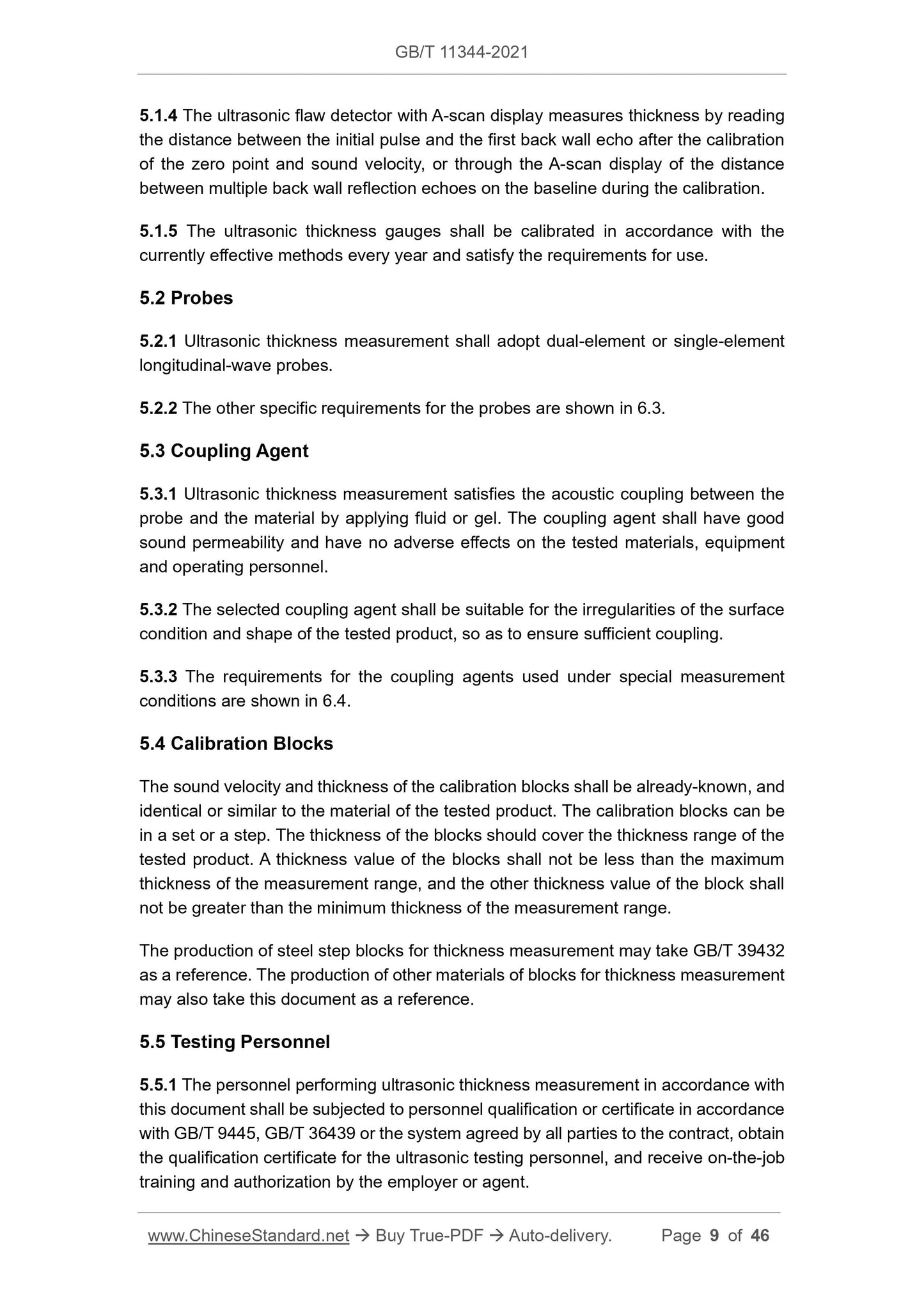
5.1.4 The ultrasonic flaw detector with A-scan display measures thickness by reading
the distance between the initial pulse and the first back wall echo after the calibration
of the zero point and sound velocity, or through the A-scan display of the distance
between multiple back wall reflection echoes on the baseline during the calibration.
5.1.5 The ultrasonic thickness gauges shall be calibrated in accordance with the
currently effective methods every year and satisfy the requirements for use.
5.2 Probes
5.2.1 Ultrasonic thickness measurement shall adopt dual-element or single-element
longitudinal-wave probes.
5.2.2 The other specific requirements for the probes are shown in 6.3.
5.3 Coupling Agent
5.3.1 Ultrasonic thickness measurement satisfies the acoustic coupling between the
probe and the material by applying fluid or gel. The coupling agent shall have good
sound permeability and have no adverse effects on the tested materials, equipment
and operating personnel.
5.3.2 The selected coupling agent shall be suitable for the irregularities of the surface
condition and shape of the tested product, so as to ensure sufficient coupling.
5.3.3 The requirements for the coupling agents used under special measurement
conditions are shown in 6.4.
5.4 Calibration Blocks
The sound velocity and thickness of the calibration blocks shall be already-known, and
identical or similar to the material of the tested product. The calibration blocks can be
in a set or a step. The thickness of the blocks should cover the thickness range of the
tested product. A thickness value of the blocks shall not be less than the maximum
thickness of the measurement range, and the other thickness value of the block shall
not be greater than the minimum thickness of the measurement range.
The production of steel step blocks for thickness measurement may take GB/T 39432
as a reference. The production of other materials of blocks for thickness measurement
may also take this document as a reference.
5.5 Testing Personnel
5.5.1 The personnel performing ultrasonic thickness measurement in accordance with
this document shall be subjected to personnel qualification or certificate in accordance
with GB/T 9445, GB/T 36439 or the system agreed by all parties to the contract, obtain
the qualification certificate for the ultrasonic testing personnel, and receive on-the-job
training and authorization by the employer or agent.
5.5.2 The testing personnel shall understand the characteristics of the tested product
and material.
6 Measurement Preparation
6.1 Surface Condition
6.1.1 The surface of the tested product shall be clean and flat, and free of loose surface
or non-sticky coatings. The measurement contact area shall be not less than 2 times
the diameter of the probe. Poor contact may cause the loss of acoustic energy and
changes in signal and sound beam propagation paths.
6.1.2 If there is a coating on the measurement surface, then, the coating shall be well-
combined with the material. The existence of close-fitting coatings (such as: paint and
enamel, etc.) is allowed. Only a few thickness gauges can measure the thickness of
the coating. When measuring the thickness of a coated product, the thickness of the
coating and the sound velocity shall be already-known, otherwise, Method 3 (multiple-
echo method) shall be adopted for the measurement.
6.1.3 Generally, the surface of corroded and abrasive products is relatively rough and
a little corroded, or there may be other defects (see Appendix B). The corroded surface
shall be polished to remove rust spots. During polishing, the thickness shall not be
reduced to below the acceptable minimum value.
6.2 Selection of Methods
6.2.1 General requirements
6.2.1.1 Ultrasonic thickness measurement is usually applied to the following two fields:
---measurement during manufacture;
---in-service measurement of residual wall thickness.
6.2.1.2 In accordance with the material, geometrical shape and thickness of the tested
product, as well as the requirements for measurement accuracy, appropriate
instruments and measurement methods shall be selected. See Appendix C and
Appendix D.
6.2.1.3 The accuracy of thickness measurement depends on the accuracy of acoustic
time measurement. Adopt different modes for the time measurement (zero-crossing
measurement, leading-edge measurement and peak-value measurement). The
accuracy of Method 3 (multiple-echo method) is higher than that of Method 1 and
Method 2. When the measurement is conducted on the basis of different frequencies,
the measurement accuracy of high-frequency probe is higher than that of low-
frequency probe.
narrow sound beam width, so as to accurately measure the restricted area, and
penetrate the entire thickness range.
6.3.3 For thin materials, high-damping and high-frequency probes are generally used.
High-frequency (10 MHz or higher) delay block probe can be used for the
measurement of steel materials with a thickness of about 0.6 mm; dual-element probes
with a small focal length may also be adopted for the measurement of thin materials.
For the dual-element probes, the focal length range shall cover the thickness range of
the tested product.
6.3.4 When measuring products with a relatively small thickness, the delay block probe
and Method 2 or Method 3 may be used for the measurement. When the acoustic
impedance of the delay block material is relatively low, for example, plastic delay block
being placed on the metal for measurement, the interface echo may generate a phase
shift, which shall be corrected to obtain accurate measurement results. Some
thickness gauges have the function of automatic correction.
6.3.5 When the surface temperature of the material is relatively high, and the delay
block is used as a thermal barrier, the delay block shall be able to withstand the
temperature of the tested product. Before measurement, the influence of temperature
on the acoustic characteristics of the delay block (acoustic attenuation and sound
velocity drift) shall be grasped. The probe manufacturer shall provide the temperature
range, in which, the probe can be used, and the service time under the measurement
temperature.
6.3.6 In accordance with different thicknesses and materials, the frequency range of
the probes may be between 100 kHz for the measurement of high-attenuation
materials and 50 MHz for the measurement of thin metals sheets.
6.3.7 If the dual-element probe is used, the error of the V-shaped path of acoustic wave
transmission shall be compensated. Generally, when measuring thin materials, the
propagation time of the dual-element probe no longer has a linear relationship with the
thickness. The smaller the measured thickness is, the more serious the non-linearity
becomes. The schematic diagram of the variation is shown in Figure 2 a); the typical
error value is shown in Figure 2 b).
required for measurement recommended by the manufacturer.
6.4.4 Measurement in hazardous environment
6.4.4.1 When measuring in hazardous environment, the current laws and regulations
on safety shall be strictly abided by.
6.4.4.2 In a corrosive environment, the coupling agent shall not adversely react with
the environment and shall maintain the acoustic characteristics.
7 Instrument Settings
7.1 Settings of Ultrasonic Flaw Detector with A-scan display
7.1.1 Combination of ultrasonic flaw detector with A-scan display and direct-
contact single-element probe
7.1.1.1 The starting point of display is synchronized with the initial pulse, and the time
baseline shall be linear. The entire thickness range is displayed on the A-scan.
7.1.1.2 Fine-tune the delay control and subtract the propagation time in the protective
film. The calibration blocks shall provide at least two thicknesses covering the
measured thickness range, so as to calibrate the accuracy of the entire measurement
range.
7.1.1.3 Place the probe on a block with already-known thickness; adjust the instrument
control (sound velocity calibration, range, scanning or sound velocity), until the echo
displays an appropriate thickness reading.
7.1.1.4 On the block whose reading value is less than the thickness value, examine
and adjust to improve the accuracy of the system. If necessary, re-verify on the
intermediate thickness of the step block.
7.1.2 Combination of ultrasonic flaw detector with A-scan display and delay
block single-element probe
7.1.2.1 When using the delay block single-element probe, the instrument shall be able
to correct the time of passing the delay block, so that it can correspond to zero
thickness at the end of the delay. The instrument shall have “delay” control or electronic
automatic zero adjustment function.
7.1.2.2 If the sound velocity can be adjusted in advance to the sound velocity of a given
material, then, it can be calibrated through the method of adjusting the delay control,
until the instrument displays the correct thickness value. If the sound velocity cannot
be set, the following methods may also be used to set the instrument.
a) Use at least two blocks. The thickness of one test block is not smaller than
7.1.4.2 After the basic setting is completed, adjust the scan delay. For example, the
nominal thickness of the tested product is 50 mm ~ 60 mm, the calibration block is 10
mm, and the thickness range is also 50 mm ~ 60 mm. Adjust the delay control, so that
the 5th back side reflection of the calibration block is equal to 50 mm, which coincides
with the reference zero point on the A-scan display; the 6th back side echo shall be on
the right side of the calibration scanning line.
7.1.4.3 After setting is completed, verify on a block with an already-known approximate
total thickness.
7.1.4.4 The reading obtained on the unknown block shall be added with the value
delayed outside the fluorescent screen. For example, if the reading is 4 mm, then, the
total thickness is 54 mm.
7.1.5 Instrument settings for thickness measurement of high-attenuation
materials
For high-attenuation materials, Method 4 (through-transmission method) may be
adopted for thickness measurement. The transmitted pulse indication may be used to
indicate a zero time pulse; set it to zero scale and set the location of the received pulse
signal to align with the already-known thickness on the scale.
7.2 Settings of Digital Direct-reading Ultrasonic Thickness Gauge
7.2.1 The instrument shall have the functions of “sound velocity setting” (or “material
selection” or “sound velocity correction”) and “zero correction”.
7.2.2 Usually, the blocks with the same material as the tested product are used. One
with a thickness not smaller than the maximum value of the measured thickness, and
the other with a thickness not greater than the minimum value of the measured
thickness.
7.2.3 The probe is placed on the thicker block; adjust the “sound velocity setting” of the
instrument, so that the reading displayed by the thickness gauge is close to the known
value.
7.2.4 The probe is placed on the thinner block; adjust the “zero correction” of the
instrument, so that the reading displayed by the thickness gauge is close to the known
value.
7.2.5 Repeat 7.2.3 and 7.2.4, until correct readings can be obt...
Delivery: 9 seconds. Download (& Email) true-PDF + Invoice.
Get Quotation: Click GB/T 11344-2021 (Self-service in 1-minute)
Historical versions (Master-website): GB/T 11344-2021
Preview True-PDF (Reload/Scroll-down if blank)
GB/T 11344-2021
GB
NATIONAL STANDARD OF THE
PEOPLE’S REPUBLIC OF CHINA
ICS 19.100
CCS J 04
Replacing GB/T 11344-2008
Non-destructive Testing - Ultrasonic Thickness
Measurement
(ISO 16809:2017, NEQ)
ISSUED ON: MAY 21, 2021
IMPLEMENTED ON: DECEMBER 1, 2021
Issued by: State Administration for Market Regulation;
Standardization Administration of the People’s Republic of
China.
Table of Contents
Foreword ... 3
1 Scope ... 5
2 Normative References ... 5
3 Terms and Definitions... 5
4 Method Summary ... 5
5 General Requirements ... 8
6 Measurement Preparation ... 10
7 Instrument Settings ... 14
8 Testing Reports and Records ... 17
Appendix A (informative) Ultrasonic Sound Velocity of Common Engineering
Application Materials ... 19
Appendix B (informative) Ultrasonic Thickness Measurement of Corrosion of
Vessels and Pipelines ... 22
Appendix C (informative) Selection of Measurement Method ... 29
Appendix D (informative) Factors Affecting Measurement Accuracy ... 33
Appendix E (informative) Instrument Settings under Special Testing Conditions
... 44
Bibliography ... 46
Non-destructive Testing - Ultrasonic Thickness
Measurement
1 Scope
This Standard specifies the ultrasonic thickness measurement through the ultrasonic
pulse-echo contact method.
This Standard is applicable to the ultrasonic thickness measurement of metal and non-
metal materials.
2 Normative References
The contents of the following documents constitute the indispensable clauses of this
document through the normative references. In terms of references with a specified
date, only versions with a specified date are applicable to this document. In terms of
references without a specified date, the latest version (including all the modifications)
is applicable to this document.
GB/T 9445 Non-destructive Testing - Qualification and Certification of NDT Personnel
(GB/T 9445-2015, ISO 9712:2012, IDT)
GB/T 12604.1 Non-destructive Testing - Terminology - Ultrasonic Testing (GB/T
12604.1-2020, ISO 5577:2017, MOD)
GB/T 20737 Non-destructive Testing - General Terms and Definitions (GB/T 20737-
2006, ISO/TS 18173:2005, IDT)
GB/T 36439 Non-destructive Testing - Certification and Qualification of Aerospace
Non-destructive Testing Personnel
3 Terms and Definitions
The terms and definitions defined in GB/T 12604.1 and GB/T 20737 are applicable to
this document.
4 Method Summary
4.1 By measuring the time for the ultrasonic signals transmitted by the probe to pass
through the measured material for one, two or multiple times, the thickness of the
measured material is determined. The thickness is calculated by dividing the product
of the already-known sound velocity and the pulse echo time by the number of pass-
5.1.4 The ultrasonic flaw detector with A-scan display measures thickness by reading
the distance between the initial pulse and the first back wall echo after the calibration
of the zero point and sound velocity, or through the A-scan display of the distance
between multiple back wall reflection echoes on the baseline during the calibration.
5.1.5 The ultrasonic thickness gauges shall be calibrated in accordance with the
currently effective methods every year and satisfy the requirements for use.
5.2 Probes
5.2.1 Ultrasonic thickness measurement shall adopt dual-element or single-element
longitudinal-wave probes.
5.2.2 The other specific requirements for the probes are shown in 6.3.
5.3 Coupling Agent
5.3.1 Ultrasonic thickness measurement satisfies the acoustic coupling between the
probe and the material by applying fluid or gel. The coupling agent shall have good
sound permeability and have no adverse effects on the tested materials, equipment
and operating personnel.
5.3.2 The selected coupling agent shall be suitable for the irregularities of the surface
condition and shape of the tested product, so as to ensure sufficient coupling.
5.3.3 The requirements for the coupling agents used under special measurement
conditions are shown in 6.4.
5.4 Calibration Blocks
The sound velocity and thickness of the calibration blocks shall be already-known, and
identical or similar to the material of the tested product. The calibration blocks can be
in a set or a step. The thickness of the blocks should cover the thickness range of the
tested product. A thickness value of the blocks shall not be less than the maximum
thickness of the measurement range, and the other thickness value of the block shall
not be greater than the minimum thickness of the measurement range.
The production of steel step blocks for thickness measurement may take GB/T 39432
as a reference. The production of other materials of blocks for thickness measurement
may also take this document as a reference.
5.5 Testing Personnel
5.5.1 The personnel performing ultrasonic thickness measurement in accordance with
this document shall be subjected to personnel qualification or certificate in accordance
with GB/T 9445, GB/T 36439 or the system agreed by all parties to the contract, obtain
the qualification certificate for the ultrasonic testing personnel, and receive on-the-job
training and authorization by the employer or agent.
5.5.2 The testing personnel shall understand the characteristics of the tested product
and material.
6 Measurement Preparation
6.1 Surface Condition
6.1.1 The surface of the tested product shall be clean and flat, and free of loose surface
or non-sticky coatings. The measurement contact area shall be not less than 2 times
the diameter of the probe. Poor contact may cause the loss of acoustic energy and
changes in signal and sound beam propagation paths.
6.1.2 If there is a coating on the measurement surface, then, the coating shall be well-
combined with the material. The existence of close-fitting coatings (such as: paint and
enamel, etc.) is allowed. Only a few thickness gauges can measure the thickness of
the coating. When measuring the thickness of a coated product, the thickness of the
coating and the sound velocity shall be already-known, otherwise, Method 3 (multiple-
echo method) shall be adopted for the measurement.
6.1.3 Generally, the surface of corroded and abrasive products is relatively rough and
a little corroded, or there may be other defects (see Appendix B). The corroded surface
shall be polished to remove rust spots. During polishing, the thickness shall not be
reduced to below the acceptable minimum value.
6.2 Selection of Methods
6.2.1 General requirements
6.2.1.1 Ultrasonic thickness measurement is usually applied to the following two fields:
---measurement during manufacture;
---in-service measurement of residual wall thickness.
6.2.1.2 In accordance with the material, geometrical shape and thickness of the tested
product, as well as the requirements for measurement accuracy, appropriate
instruments and measurement methods shall be selected. See Appendix C and
Appendix D.
6.2.1.3 The accuracy of thickness measurement depends on the accuracy of acoustic
time measurement. Adopt different modes for the time measurement (zero-crossing
measurement, leading-edge measurement and peak-value measurement). The
accuracy of Method 3 (multiple-echo method) is higher than that of Method 1 and
Method 2. When the measurement is conducted on the basis of different frequencies,
the measurement accuracy of high-frequency probe is higher than that of low-
frequency probe.
narrow sound beam width, so as to accurately measure the restricted area, and
penetrate the entire thickness range.
6.3.3 For thin materials, high-damping and high-frequency probes are generally used.
High-frequency (10 MHz or higher) delay block probe can be used for the
measurement of steel materials with a thickness of about 0.6 mm; dual-element probes
with a small focal length may also be adopted for the measurement of thin materials.
For the dual-element probes, the focal length range shall cover the thickness range of
the tested product.
6.3.4 When measuring products with a relatively small thickness, the delay block probe
and Method 2 or Method 3 may be used for the measurement. When the acoustic
impedance of the delay block material is relatively low, for example, plastic delay block
being placed on the metal for measurement, the interface echo may generate a phase
shift, which shall be corrected to obtain accurate measurement results. Some
thickness gauges have the function of automatic correction.
6.3.5 When the surface temperature of the material is relatively high, and the delay
block is used as a thermal barrier, the delay block shall be able to withstand the
temperature of the tested product. Before measurement, the influence of temperature
on the acoustic characteristics of the delay block (acoustic attenuation and sound
velocity drift) shall be grasped. The probe manufacturer shall provide the temperature
range, in which, the probe can be used, and the service time under the measurement
temperature.
6.3.6 In accordance with different thicknesses and materials, the frequency range of
the probes may be between 100 kHz for the measurement of high-attenuation
materials and 50 MHz for the measurement of thin metals sheets.
6.3.7 If the dual-element probe is used, the error of the V-shaped path of acoustic wave
transmission shall be compensated. Generally, when measuring thin materials, the
propagation time of the dual-element probe no longer has a linear relationship with the
thickness. The smaller the measured thickness is, the more serious the non-linearity
becomes. The schematic diagram of the variation is shown in Figure 2 a); the typical
error value is shown in Figure 2 b).
required for measurement recommended by the manufacturer.
6.4.4 Measurement in hazardous environment
6.4.4.1 When measuring in hazardous environment, the current laws and regulations
on safety shall be strictly abided by.
6.4.4.2 In a corrosive environment, the coupling agent shall not adversely react with
the environment and shall maintain the acoustic characteristics.
7 Instrument Settings
7.1 Settings of Ultrasonic Flaw Detector with A-scan display
7.1.1 Combination of ultrasonic flaw detector with A-scan display and direct-
contact single-element probe
7.1.1.1 The starting point of display is synchronized with the initial pulse, and the time
baseline shall be linear. The entire thickness range is displayed on the A-scan.
7.1.1.2 Fine-tune the delay control and subtract the propagation time in the protective
film. The calibration blocks shall provide at least two thicknesses covering the
measured thickness range, so as to calibrate the accuracy of the entire measurement
range.
7.1.1.3 Place the probe on a block with already-known thickness; adjust the instrument
control (sound velocity calibration, range, scanning or sound velocity), until the echo
displays an appropriate thickness reading.
7.1.1.4 On the block whose reading value is less than the thickness value, examine
and adjust to improve the accuracy of the system. If necessary, re-verify on the
intermediate thickness of the step block.
7.1.2 Combination of ultrasonic flaw detector with A-scan display and delay
block single-element probe
7.1.2.1 When using the delay block single-element probe, the instrument shall be able
to correct the time of passing the delay block, so that it can correspond to zero
thickness at the end of the delay. The instrument shall have “delay” control or electronic
automatic zero adjustment function.
7.1.2.2 If the sound velocity can be adjusted in advance to the sound velocity of a given
material, then, it can be calibrated through the method of adjusting the delay control,
until the instrument displays the correct thickness value. If the sound velocity cannot
be set, the following methods may also be used to set the instrument.
a) Use at least two blocks. The thickness of one test block is not smaller than
7.1.4.2 After the basic setting is completed, adjust the scan delay. For example, the
nominal thickness of the tested product is 50 mm ~ 60 mm, the calibration block is 10
mm, and the thickness range is also 50 mm ~ 60 mm. Adjust the delay control, so that
the 5th back side reflection of the calibration block is equal to 50 mm, which coincides
with the reference zero point on the A-scan display; the 6th back side echo shall be on
the right side of the calibration scanning line.
7.1.4.3 After setting is completed, verify on a block with an already-known approximate
total thickness.
7.1.4.4 The reading obtained on the unknown block shall be added with the value
delayed outside the fluorescent screen. For example, if the reading is 4 mm, then, the
total thickness is 54 mm.
7.1.5 Instrument settings for thickness measurement of high-attenuation
materials
For high-attenuation materials, Method 4 (through-transmission method) may be
adopted for thickness measurement. The transmitted pulse indication may be used to
indicate a zero time pulse; set it to zero scale and set the location of the received pulse
signal to align with the already-known thickness on the scale.
7.2 Settings of Digital Direct-reading Ultrasonic Thickness Gauge
7.2.1 The instrument shall have the functions of “sound velocity setting” (or “material
selection” or “sound velocity correction”) and “zero correction”.
7.2.2 Usually, the blocks with the same material as the tested product are used. One
with a thickness not smaller than the maximum value of the measured thickness, and
the other with a thickness not greater than the minimum value of the measured
thickness.
7.2.3 The probe is placed on the thicker block; adjust the “sound velocity setting” of the
instrument, so that the reading displayed by the thickness gauge is close to the known
value.
7.2.4 The probe is placed on the thinner block; adjust the “zero correction” of the
instrument, so that the reading displayed by the thickness gauge is close to the known
value.
7.2.5 Repeat 7.2.3 and 7.2.4, until correct readings can be obt...
Share