1
/
of
8
www.ChineseStandard.us -- Field Test Asia Pte. Ltd.
GB/T 1216-2018 English PDF (GB/T1216-2018)
GB/T 1216-2018 English PDF (GB/T1216-2018)
Regular price
$150.00
Regular price
Sale price
$150.00
Unit price
/
per
Shipping calculated at checkout.
Couldn't load pickup availability
GB/T 1216-2018: External micrometer
Delivery: 9 seconds. Download (& Email) true-PDF + Invoice.
Get Quotation: Click GB/T 1216-2018 (Self-service in 1-minute)
Historical versions (Master-website): GB/T 1216-2018
Preview True-PDF (Reload/Scroll-down if blank)
GB/T 1216-2018
External micrometer
ICS 17.040.30
J42
National Standards of People's Republic of China
Replace GB/T 1216-2004
Outside diameter micrometer
Published on.2018-05-14
2018-12-01 implementation
State market supervision and administration
China National Standardization Administration issued
Foreword
This standard was drafted in accordance with the rules given in GB/T 1.1-2009.
This standard replaces GB/T 1216-2004 "outer diameter micrometer". This standard is compared with GB/T 1216-2004, except for editorial modifications.
In addition, the main technical changes are as follows.
--- Scope of application removed the outer diameter micrometer with a graduation value of 0.005mm (see Chapter 1, Chapter 1 of the.2004 edition);
--- Modified the definition of the outer diameter micrometer (see 3.1, 3.1 of the.2004 edition);
--- Increased the type of outer diameter micrometer (see 4.1.1);
--- Increased the type and description of the outer diameter micrometer reading device (see 4.1.2);
--- Modified the basic parameters of the outer diameter micrometer (see 4.2,.2004 version 4.2);
--- Modified the deformation requirements of the ruler (see 5.3.1, 5.3.1 of the.2004 edition);
---Modified the technical requirements for micrometer screw and anvil (see 5.4,.2004 edition 5.4);
--- Revised the technical requirements for interaction (see 5.5, 5.5 and Appendix A of the.2004 edition);
---Modify the "force measuring device" as "locking device" (see 5.6, 5.6 of the.2004 edition);
---Modify "ratchet" as "force measuring device" (see 5.7, 5.7 of.2004 edition);
---Modified the technical requirements of the measuring surface, deleted the appendix "measuring surface deviation value", the corresponding content is placed in the text (see 5.8,.2004 edition)
5.8 and Appendix B);
---Modified the ruler spacing technical requirements (see 5.9.1,.2004 version 5.9.1);
--- Increased the outer diameter micrometer score line coincidence requirement of the graduation value of 0.001mm (see 5.9.5);
---Modified "digital display device" as "counter digital reading device" and modified the corresponding requirements (see 5.10,.2004 edition)
5.10);
--- Revised the technical requirements for the maximum allowable error (see 5.11, 5.11 of the.2004 edition);
--- Revised the technical requirements for proofreading gauges (see 5.12, 5.12 of the.2004 edition);
--- Modified the inspection requirements of the interaction, deleted the appendix "axial yaw and radial oscillating", the corresponding content is placed in the text (see 6.4,
Version 6.4 and Appendix A of the.2004 edition;
---Modified the measurement error of the measurement surface error (see 6.6, 6.6 of.2004 edition);
--- Revised the inspection requirements for the indication error of the outer diameter micrometer (see 6.7, 6.7 of the.2004 edition).
This standard was proposed by the China Machinery Industry Federation.
This standard is under the jurisdiction of the National Standardization Technical Committee for Measuring Instruments (SAC/TC132).
This standard is drafted by. Chengdu Tool Research Institute Co., Ltd.
Participated in the drafting of this standard. Suzhou McLong Measuring Technology Co., Ltd., Guilin Measuring Tool Limited Liability Company, Chengdu Massing Tool
Group Co., Ltd., Harbin Measuring and Cutting Tool Group Co., Ltd., Guilin Guanglu Digital Measurement and Control Co., Ltd., Guangxi Zhuang Autonomous Region
Testing Institute, Liaoning Institute of Metrology.
The main drafters of this standard. Xu Gang, Jiang Zhigang, Huang Xiaobin, Wei Gaihong, Luo Weibing, Zhang Wei, Dong Zhongxin, Chen Ping, Ding Wen.
The previous versions of the standards replaced by this standard are.
---GB/T 1216-1975, GB/T 1216-1985, GB/T 1216-2004.
Outside diameter micrometer
1 Scope
This standard specifies the terms and definitions, types and basic parameters, requirements, and external diameter micrometers (excluding electronic digital display outer diameter micrometers).
Inspection methods and signs and packaging.
This standard applies to outer diameter micrometers with graduation values of 0.01mm, 0.001mm, 0.002mm and upper limit of measurement range up to 1000mm.
(Does not include electronic digital display outer diameter micrometer).
2 Normative references
The following documents are indispensable for the application of this document. For dated references, only dated versions apply to this article.
Pieces. For undated references, the latest edition (including all amendments) applies to this document.
GB/T 1800.2-2009 Geometrical Product Specifications (GPS) Limits and fits. Part 2. Standard tolerance classes and
Limit deviation table
GB/T 17163-2008 Geometric quantity measuring instrument terminology basic terminology
GB/T 17164-2008 Geometric quantity measuring instrument terminology product terminology
3 Terms and definitions
The following terms and definitions as defined in GB/T 17163-2008 and GB/T 17164-2008 apply to this document.
3.1
Using the screw pair to convert the rotation angle of the micrometer screw into the axial displacement of the micrometer screw, and the distance between the two measuring surfaces on the scale frame
An external measuring device that performs readings.
Note. Rewrite GB/T 17164-2008, definition 2.3.2.
3.2
Micrometer maximum allowable error maximumpermissibleerrorofmeasuringhead
The influence of the anvil and the ruler is neglected, and only the maximum allowable error of the indication of the micrometer is specified.
4 type and basic parameters
4.1 type
4.1.1 Outer diameter micrometer main type
The type of the outer diameter micrometer is shown in Figure 1, and the illustration is for illustration purposes only.
The anvil of the outer diameter micrometer can be made fixed, replaceable or adjustable (or movable).
The outer diameter micrometer readings have analog scale readings and counter digital readings.
The outer diameter micrometer should be equipped with a zero adjustment tool. The outer diameter micrometer of the lower limit of the measurement range greater than or equal to 25mm should be accompanied by proofreading.
Measuring rod.
a) Fixed anvil fixed micrometer
b) Anvil can be replaced with an outer diameter micrometer
Figure 1 Schematic diagram of the outer diameter micrometer
c) Anvil can adjust the position (or movable) outer diameter micrometer
Description.
1---measurement surface;
2---anvil;
3---micrometer screw;
4---foot frame;
5---insulation device;
6---locking device;
7---fixed casing;
8 --- baseline;
9 --- ruler analog reading device;
10---microtube;
11---force measuring device;
12---counter digital reading device;
13---replaceable anvil;
14---Adjustable position (or movable) anvil.
Figure 1 (continued)
4.1.2 Outside diameter micrometer reading device
4.1.2.1 Analog scale reading device
The analog scale reading device is shown in Figures 2 and 3.
Description.
1---main ruler;
2---sub-scale.
Note. The reading in the figure is 35.04mm.
Figure 2 Analog scale reading device (the pitch of the micro screw is 0.5mm, the graduation value is 0.01mm)
Description.
1---main ruler;
2---sub-scale;
3--- vernier ruler.
Note. The reading in the figure is 5.005mm.
Figure 3 Analog scale reading device (the pitch of the micro screw is 0.5mm, the graduation value is 0.001mm)
4.1.2.2 Counter digital reading device
The counter digital reading device is shown in Figure 4.
Description.
1---Counter digital reading device.
Figure 4 counter digital reading device
4.2 Basic parameters
The basic dimensions of the outer diameter micrometer are shown in Figure 5 and Table 1.
The lower limit of the measurement range of the outer diameter micrometer is preferably 0, or an integral multiple of the range.
Figure 5 Basic dimensions of the outer diameter micrometer
Table 1 Basic dimensions are in millimeters
Basic size nominal value
The nominal diameter of the portion of the micrometer screw and the anvil that protrudes from the frame, D1a 5, 6.35, 6.5, 7.5, 8.0
The length of the anvil is extended by the frame, L1 ≥ 3
Measuring the length of the micro screw protruding from the frame at the upper limit of the measuring range, L2 ≥ 3
Upper limit of measuring range of outer diameter micrometer, L3 ≤1000
The range of the outer diameter micrometer, L4a 13,15,25,50
Ruler depth, L5 ≥ 0.5 × L3
The outer diameter micrometer micrometer screw pitch a 0.5,1
a Manufacturer may choose other parameters.
5 requirements
5.1 Appearance
The outer diameter micrometer should not have defects such as rust, bumps, scratches, cracks, etc. that affect the performance.
5.2 Materials
5.2.1 The ruler should be made of steel, malleable cast iron or other similar properties.
5.2.2 The micrometer screw and the anvil should be made of alloy tool steel, stainless steel or other similar properties; the measuring surface should be made of hard alloy.
Or other wear resistant materials.
5.3 ruler
5.3.1 The ruler should have sufficient rigidity. When the ruler acts 10N along the axis of the micrometer screw, the deformation should not be greater than
The provisions of Table 2.
5.3.2 Thermal insulation shall be installed on the ruler.
Table 2 shows the maximum allowable error, parallelism tolerance and deformation of the frame when subjected to 10N force
Measuring range
Mm
The maximum allowable error parallelism tolerance is the amount of deformation when the frame is subjected to 10N force
Mm
0~15,0~25
25~50
50~75,75~100
100~125, 125~150
150~175,175~200
200~225, 225~250
250~275, 275~300
4(2)a
5(3)a
2(1)a
2(1.5)a
3(2)a
Table 2 (continued)
Measuring range
Mm
The maximum allowable error parallelism tolerance is the amount of deformation when the frame is subjected to 10N force
Mm
300~325,325~350 10 5 8
350~375, 375~400 11 6 9
400~425,425~450 12 6 10
450~475, 475~500 13 7 11
500~600 14 9 12
600~700 16 11 14
700~800 18 13 16
800~900 20 15 18
900~1000 22 17 20
a The value in parentheses ( ) is the corresponding requirement for the outer diameter micrometer with a graduation value of 0.001 mm.
5.4 Micrometer screw and anvil
5.4.1 The nominal diameter D1 of the smooth cylindrical part of the micrometer screw and the anvil that protrudes out of the frame is shown in Table 1.
5.4.2 Replaceable anvils The length of the extension of the ruler should be equal to the integral of the range or range of the outer diameter micrometer.
5.4.3 The adjustable position (or movable) of the anvil shall be extended to the range of the outer diameter micrometer after the position adjustment is adjusted to be equal to the range or amount of the outer diameter micrometer.
An integer multiple of the process.
5.5 Interaction
5.5.1 The micrometer screw and nut should be fully meshed within the full range, and the fit should be good. There should be no jamming and obvious axial turbulence.
The axial turbulence value should preferably be no more than 0.01 mm.
5.5.2 The fit between the smooth cylindrical part of the micrometer screw and the sleeve of the micrometer screw should be good, and there should be no obvious radial oscillation. Radial
The swing value should preferably be no more than 0.01 mm.
5.6 locking device
The outer diameter micrometer locking device should effectively lock the micrometer screw. Before and after locking, the distance between the two measuring surfaces should not change more than 2μm.
And the parallelism between the two measuring surfaces shall comply with the provisions of 5.8.2.
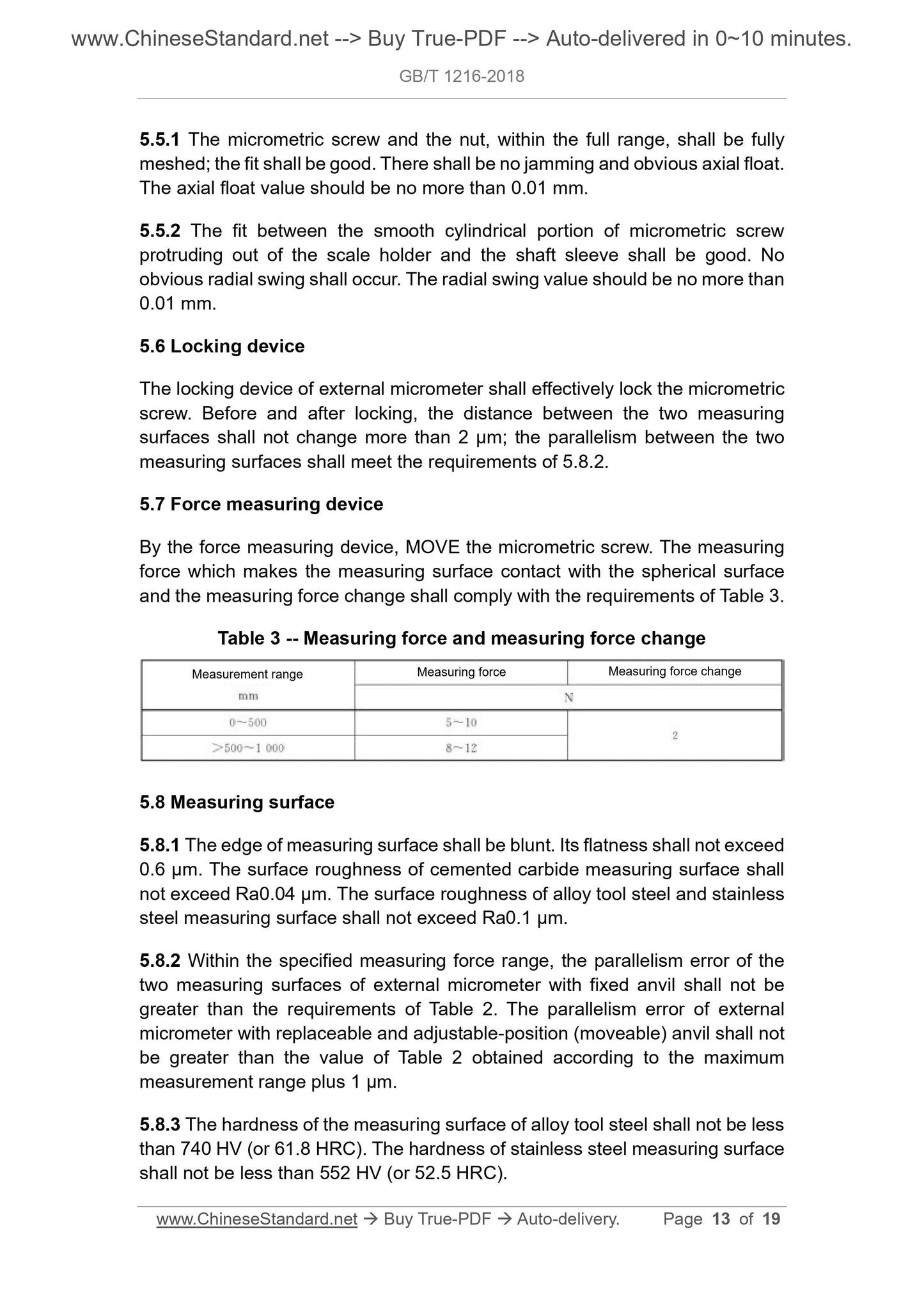
5.7 Force measuring device
The measuring force and the measuring force of the measuring surface in contact with the spherical surface shall be changed by the force measuring device to move the micrometer screw to meet the requirements of Table 3.
Table 3 Measurement force, measurement force change
Measuring range
Mm
Measuring force measurement force change
0~500 5~10
>500~1000 8~12
5.8 Measuring surface
5.8.1 The edge of the measuring surface shall be blunt and its flatness shall not exceed 0.6 μm. The surface roughness of the cemented carbide measuring surface should not be greater than
Ra 0.04 μm; the surface roughness of the alloy tool steel and stainless steel measuring surface should not be greater than Ra 0.1 μm.
5.8.2 Within the specified measuring force range, the parallelism error of the two measuring surfaces of the fixed outer diameter fixed micrometer shall not exceed the requirements of Table 2;
The anvil can be replaced and the anvil can be adjusted (or movable). The parallelism error of the outer diameter micrometer should not be greater than the maximum measurement range.
The value of Table 2 was increased by 1 μm.
5.8.3 The hardness of the measuring surface of the alloy tool steel shall not be less than 740HV (or 61.8HRC); the hardness of the stainless steel measuring surface shall not be less than
552HV (or 52.5HRC).
5.8.4 There should be no obvious deviation between the two measuring surfaces of the outer diameter micrometer, and the deviation error should not be greater than that specified in Table 4.
Table 4 Deviation error unit is mm
Measuring range upper limit error
25 0.05
50 0.10
75 0.15
100 0.20
125 0.25
150 0.30
175 0.35
Measuring range upper limit error
200 0.40
>200~250 0.50
>250~300 0.60
>300~400 0.80
>400~600 1.20
>600~800 1.60
>800~1000 2.00
5.9 ruler
5.9.1 There should be 50 or 100 equally spaced scales on the differential cylinder. The spacing between the scales should not be less than 0.8mm. The width of the scale marking should be
Between 0.08mm and 0.20mm.
5.9.2 The angle of the conical surface of the differential cylinder should be between 7 ° and 20 °, and the distance from the edge of the conical surface of the differential cylinder to the surface of the fixed sleeve should not be large.
At 0.4mm.
5.9.3 The scale marking on the fixed sleeve and the scale marking on the differential cylinder should be clear, and the difference in width should not exceed 0.03 mm.
5.9.4 When the outer diameter micrometer ...
Delivery: 9 seconds. Download (& Email) true-PDF + Invoice.
Get Quotation: Click GB/T 1216-2018 (Self-service in 1-minute)
Historical versions (Master-website): GB/T 1216-2018
Preview True-PDF (Reload/Scroll-down if blank)
GB/T 1216-2018
External micrometer
ICS 17.040.30
J42
National Standards of People's Republic of China
Replace GB/T 1216-2004
Outside diameter micrometer
Published on.2018-05-14
2018-12-01 implementation
State market supervision and administration
China National Standardization Administration issued
Foreword
This standard was drafted in accordance with the rules given in GB/T 1.1-2009.
This standard replaces GB/T 1216-2004 "outer diameter micrometer". This standard is compared with GB/T 1216-2004, except for editorial modifications.
In addition, the main technical changes are as follows.
--- Scope of application removed the outer diameter micrometer with a graduation value of 0.005mm (see Chapter 1, Chapter 1 of the.2004 edition);
--- Modified the definition of the outer diameter micrometer (see 3.1, 3.1 of the.2004 edition);
--- Increased the type of outer diameter micrometer (see 4.1.1);
--- Increased the type and description of the outer diameter micrometer reading device (see 4.1.2);
--- Modified the basic parameters of the outer diameter micrometer (see 4.2,.2004 version 4.2);
--- Modified the deformation requirements of the ruler (see 5.3.1, 5.3.1 of the.2004 edition);
---Modified the technical requirements for micrometer screw and anvil (see 5.4,.2004 edition 5.4);
--- Revised the technical requirements for interaction (see 5.5, 5.5 and Appendix A of the.2004 edition);
---Modify the "force measuring device" as "locking device" (see 5.6, 5.6 of the.2004 edition);
---Modify "ratchet" as "force measuring device" (see 5.7, 5.7 of.2004 edition);
---Modified the technical requirements of the measuring surface, deleted the appendix "measuring surface deviation value", the corresponding content is placed in the text (see 5.8,.2004 edition)
5.8 and Appendix B);
---Modified the ruler spacing technical requirements (see 5.9.1,.2004 version 5.9.1);
--- Increased the outer diameter micrometer score line coincidence requirement of the graduation value of 0.001mm (see 5.9.5);
---Modified "digital display device" as "counter digital reading device" and modified the corresponding requirements (see 5.10,.2004 edition)
5.10);
--- Revised the technical requirements for the maximum allowable error (see 5.11, 5.11 of the.2004 edition);
--- Revised the technical requirements for proofreading gauges (see 5.12, 5.12 of the.2004 edition);
--- Modified the inspection requirements of the interaction, deleted the appendix "axial yaw and radial oscillating", the corresponding content is placed in the text (see 6.4,
Version 6.4 and Appendix A of the.2004 edition;
---Modified the measurement error of the measurement surface error (see 6.6, 6.6 of.2004 edition);
--- Revised the inspection requirements for the indication error of the outer diameter micrometer (see 6.7, 6.7 of the.2004 edition).
This standard was proposed by the China Machinery Industry Federation.
This standard is under the jurisdiction of the National Standardization Technical Committee for Measuring Instruments (SAC/TC132).
This standard is drafted by. Chengdu Tool Research Institute Co., Ltd.
Participated in the drafting of this standard. Suzhou McLong Measuring Technology Co., Ltd., Guilin Measuring Tool Limited Liability Company, Chengdu Massing Tool
Group Co., Ltd., Harbin Measuring and Cutting Tool Group Co., Ltd., Guilin Guanglu Digital Measurement and Control Co., Ltd., Guangxi Zhuang Autonomous Region
Testing Institute, Liaoning Institute of Metrology.
The main drafters of this standard. Xu Gang, Jiang Zhigang, Huang Xiaobin, Wei Gaihong, Luo Weibing, Zhang Wei, Dong Zhongxin, Chen Ping, Ding Wen.
The previous versions of the standards replaced by this standard are.
---GB/T 1216-1975, GB/T 1216-1985, GB/T 1216-2004.
Outside diameter micrometer
1 Scope
This standard specifies the terms and definitions, types and basic parameters, requirements, and external diameter micrometers (excluding electronic digital display outer diameter micrometers).
Inspection methods and signs and packaging.
This standard applies to outer diameter micrometers with graduation values of 0.01mm, 0.001mm, 0.002mm and upper limit of measurement range up to 1000mm.
(Does not include electronic digital display outer diameter micrometer).
2 Normative references
The following documents are indispensable for the application of this document. For dated references, only dated versions apply to this article.
Pieces. For undated references, the latest edition (including all amendments) applies to this document.
GB/T 1800.2-2009 Geometrical Product Specifications (GPS) Limits and fits. Part 2. Standard tolerance classes and
Limit deviation table
GB/T 17163-2008 Geometric quantity measuring instrument terminology basic terminology
GB/T 17164-2008 Geometric quantity measuring instrument terminology product terminology
3 Terms and definitions
The following terms and definitions as defined in GB/T 17163-2008 and GB/T 17164-2008 apply to this document.
3.1
Using the screw pair to convert the rotation angle of the micrometer screw into the axial displacement of the micrometer screw, and the distance between the two measuring surfaces on the scale frame
An external measuring device that performs readings.
Note. Rewrite GB/T 17164-2008, definition 2.3.2.
3.2
Micrometer maximum allowable error maximumpermissibleerrorofmeasuringhead
The influence of the anvil and the ruler is neglected, and only the maximum allowable error of the indication of the micrometer is specified.
4 type and basic parameters
4.1 type
4.1.1 Outer diameter micrometer main type
The type of the outer diameter micrometer is shown in Figure 1, and the illustration is for illustration purposes only.
The anvil of the outer diameter micrometer can be made fixed, replaceable or adjustable (or movable).
The outer diameter micrometer readings have analog scale readings and counter digital readings.
The outer diameter micrometer should be equipped with a zero adjustment tool. The outer diameter micrometer of the lower limit of the measurement range greater than or equal to 25mm should be accompanied by proofreading.
Measuring rod.
a) Fixed anvil fixed micrometer
b) Anvil can be replaced with an outer diameter micrometer
Figure 1 Schematic diagram of the outer diameter micrometer
c) Anvil can adjust the position (or movable) outer diameter micrometer
Description.
1---measurement surface;
2---anvil;
3---micrometer screw;
4---foot frame;
5---insulation device;
6---locking device;
7---fixed casing;
8 --- baseline;
9 --- ruler analog reading device;
10---microtube;
11---force measuring device;
12---counter digital reading device;
13---replaceable anvil;
14---Adjustable position (or movable) anvil.
Figure 1 (continued)
4.1.2 Outside diameter micrometer reading device
4.1.2.1 Analog scale reading device
The analog scale reading device is shown in Figures 2 and 3.
Description.
1---main ruler;
2---sub-scale.
Note. The reading in the figure is 35.04mm.
Figure 2 Analog scale reading device (the pitch of the micro screw is 0.5mm, the graduation value is 0.01mm)
Description.
1---main ruler;
2---sub-scale;
3--- vernier ruler.
Note. The reading in the figure is 5.005mm.
Figure 3 Analog scale reading device (the pitch of the micro screw is 0.5mm, the graduation value is 0.001mm)
4.1.2.2 Counter digital reading device
The counter digital reading device is shown in Figure 4.
Description.
1---Counter digital reading device.
Figure 4 counter digital reading device
4.2 Basic parameters
The basic dimensions of the outer diameter micrometer are shown in Figure 5 and Table 1.
The lower limit of the measurement range of the outer diameter micrometer is preferably 0, or an integral multiple of the range.
Figure 5 Basic dimensions of the outer diameter micrometer
Table 1 Basic dimensions are in millimeters
Basic size nominal value
The nominal diameter of the portion of the micrometer screw and the anvil that protrudes from the frame, D1a 5, 6.35, 6.5, 7.5, 8.0
The length of the anvil is extended by the frame, L1 ≥ 3
Measuring the length of the micro screw protruding from the frame at the upper limit of the measuring range, L2 ≥ 3
Upper limit of measuring range of outer diameter micrometer, L3 ≤1000
The range of the outer diameter micrometer, L4a 13,15,25,50
Ruler depth, L5 ≥ 0.5 × L3
The outer diameter micrometer micrometer screw pitch a 0.5,1
a Manufacturer may choose other parameters.
5 requirements
5.1 Appearance
The outer diameter micrometer should not have defects such as rust, bumps, scratches, cracks, etc. that affect the performance.
5.2 Materials
5.2.1 The ruler should be made of steel, malleable cast iron or other similar properties.
5.2.2 The micrometer screw and the anvil should be made of alloy tool steel, stainless steel or other similar properties; the measuring surface should be made of hard alloy.
Or other wear resistant materials.
5.3 ruler
5.3.1 The ruler should have sufficient rigidity. When the ruler acts 10N along the axis of the micrometer screw, the deformation should not be greater than
The provisions of Table 2.
5.3.2 Thermal insulation shall be installed on the ruler.
Table 2 shows the maximum allowable error, parallelism tolerance and deformation of the frame when subjected to 10N force
Measuring range
Mm
The maximum allowable error parallelism tolerance is the amount of deformation when the frame is subjected to 10N force
Mm
0~15,0~25
25~50
50~75,75~100
100~125, 125~150
150~175,175~200
200~225, 225~250
250~275, 275~300
4(2)a
5(3)a
2(1)a
2(1.5)a
3(2)a
Table 2 (continued)
Measuring range
Mm
The maximum allowable error parallelism tolerance is the amount of deformation when the frame is subjected to 10N force
Mm
300~325,325~350 10 5 8
350~375, 375~400 11 6 9
400~425,425~450 12 6 10
450~475, 475~500 13 7 11
500~600 14 9 12
600~700 16 11 14
700~800 18 13 16
800~900 20 15 18
900~1000 22 17 20
a The value in parentheses ( ) is the corresponding requirement for the outer diameter micrometer with a graduation value of 0.001 mm.
5.4 Micrometer screw and anvil
5.4.1 The nominal diameter D1 of the smooth cylindrical part of the micrometer screw and the anvil that protrudes out of the frame is shown in Table 1.
5.4.2 Replaceable anvils The length of the extension of the ruler should be equal to the integral of the range or range of the outer diameter micrometer.
5.4.3 The adjustable position (or movable) of the anvil shall be extended to the range of the outer diameter micrometer after the position adjustment is adjusted to be equal to the range or amount of the outer diameter micrometer.
An integer multiple of the process.
5.5 Interaction
5.5.1 The micrometer screw and nut should be fully meshed within the full range, and the fit should be good. There should be no jamming and obvious axial turbulence.
The axial turbulence value should preferably be no more than 0.01 mm.
5.5.2 The fit between the smooth cylindrical part of the micrometer screw and the sleeve of the micrometer screw should be good, and there should be no obvious radial oscillation. Radial
The swing value should preferably be no more than 0.01 mm.
5.6 locking device
The outer diameter micrometer locking device should effectively lock the micrometer screw. Before and after locking, the distance between the two measuring surfaces should not change more than 2μm.
And the parallelism between the two measuring surfaces shall comply with the provisions of 5.8.2.
5.7 Force measuring device
The measuring force and the measuring force of the measuring surface in contact with the spherical surface shall be changed by the force measuring device to move the micrometer screw to meet the requirements of Table 3.
Table 3 Measurement force, measurement force change
Measuring range
Mm
Measuring force measurement force change
0~500 5~10
>500~1000 8~12
5.8 Measuring surface
5.8.1 The edge of the measuring surface shall be blunt and its flatness shall not exceed 0.6 μm. The surface roughness of the cemented carbide measuring surface should not be greater than
Ra 0.04 μm; the surface roughness of the alloy tool steel and stainless steel measuring surface should not be greater than Ra 0.1 μm.
5.8.2 Within the specified measuring force range, the parallelism error of the two measuring surfaces of the fixed outer diameter fixed micrometer shall not exceed the requirements of Table 2;
The anvil can be replaced and the anvil can be adjusted (or movable). The parallelism error of the outer diameter micrometer should not be greater than the maximum measurement range.
The value of Table 2 was increased by 1 μm.
5.8.3 The hardness of the measuring surface of the alloy tool steel shall not be less than 740HV (or 61.8HRC); the hardness of the stainless steel measuring surface shall not be less than
552HV (or 52.5HRC).
5.8.4 There should be no obvious deviation between the two measuring surfaces of the outer diameter micrometer, and the deviation error should not be greater than that specified in Table 4.
Table 4 Deviation error unit is mm
Measuring range upper limit error
25 0.05
50 0.10
75 0.15
100 0.20
125 0.25
150 0.30
175 0.35
Measuring range upper limit error
200 0.40
>200~250 0.50
>250~300 0.60
>300~400 0.80
>400~600 1.20
>600~800 1.60
>800~1000 2.00
5.9 ruler
5.9.1 There should be 50 or 100 equally spaced scales on the differential cylinder. The spacing between the scales should not be less than 0.8mm. The width of the scale marking should be
Between 0.08mm and 0.20mm.
5.9.2 The angle of the conical surface of the differential cylinder should be between 7 ° and 20 °, and the distance from the edge of the conical surface of the differential cylinder to the surface of the fixed sleeve should not be large.
At 0.4mm.
5.9.3 The scale marking on the fixed sleeve and the scale marking on the differential cylinder should be clear, and the difference in width should not exceed 0.03 mm.
5.9.4 When the outer diameter micrometer ...
Share