1
/
of
10
PayPal, credit cards. Download editable-PDF and invoice in 1 second!
GB/T 12243-2021 English PDF (GBT12243-2021)
GB/T 12243-2021 English PDF (GBT12243-2021)
Regular price
$365.00 USD
Regular price
Sale price
$365.00 USD
Unit price
/
per
Shipping calculated at checkout.
Couldn't load pickup availability
Delivery: 3 seconds. Download true-PDF + Invoice.
Get QUOTATION in 1-minute: Click GB/T 12243-2021
Historical versions: GB/T 12243-2021
Preview True-PDF (Reload/Scroll if blank)
GB/T 12243-2021: Spring loaded safety valves
GB/T 12243-2021
GB
NATIONAL STANDARD OF THE
PEOPLE’S REPUBLIC OF CHINA
ICS 13.240
CCS J 16
Replacing GB/T 12243-2005
Spring loaded safety valve
ISSUED ON: APRIL 30, 2021
IMPLEMENTED ON: NOVEMBER 01, 2021
Issued by: State Administration for Market Regulation;
Standardization Administration of the People's Republic of China.
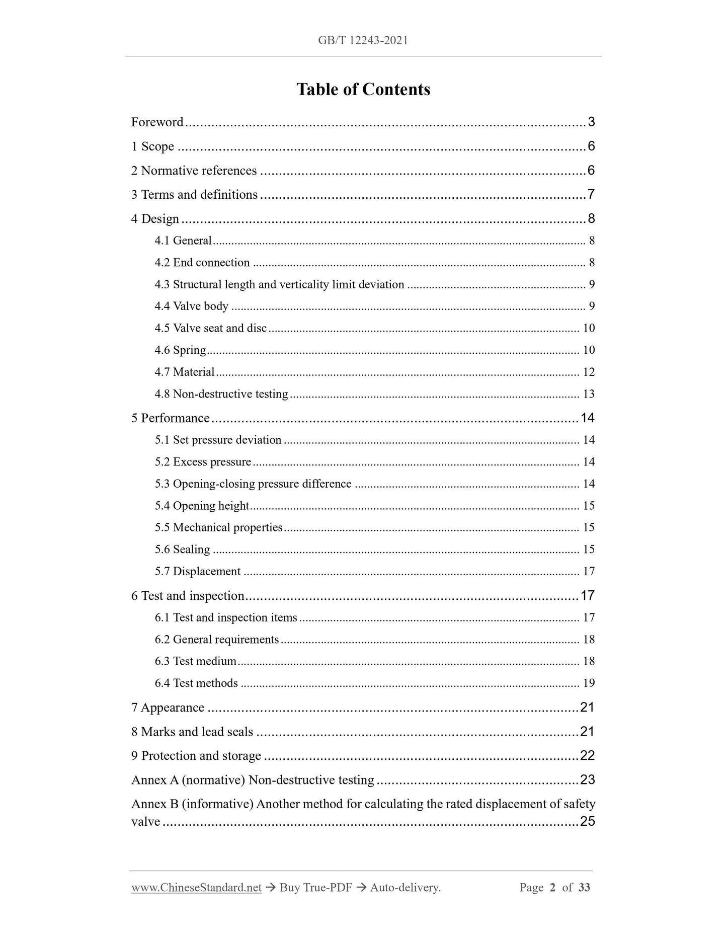
Table of Contents
Foreword ... 3
1 Scope ... 6
2 Normative references ... 6
3 Terms and definitions ... 7
4 Design ... 8
4.1 General ... 8
4.2 End connection ... 8
4.3 Structural length and verticality limit deviation ... 9
4.4 Valve body ... 9
4.5 Valve seat and disc ... 10
4.6 Spring ... 10
4.7 Material ... 12
4.8 Non-destructive testing ... 13
5 Performance ... 14
5.1 Set pressure deviation ... 14
5.2 Excess pressure ... 14
5.3 Opening-closing pressure difference ... 14
5.4 Opening height ... 15
5.5 Mechanical properties ... 15
5.6 Sealing ... 15
5.7 Displacement ... 17
6 Test and inspection ... 17
6.1 Test and inspection items ... 17
6.2 General requirements ... 18
6.3 Test medium ... 18
6.4 Test methods ... 19
7 Appearance ... 21
8 Marks and lead seals ... 21
9 Protection and storage ... 22
Annex A (normative) Non-destructive testing ... 23
Annex B (informative) Another method for calculating the rated displacement of safety
valve ... 25
Spring loaded safety valve
1 Scope
This document specifies the design, performance, test and inspection, appearance, mark
and lead seal, protection, storage and transportation for spring loaded safety valves
(hereinafter referred to as safety valves).
This document is applicable to safety valves for steam with a set pressure of
0.1MPa~42.0MPa, and flow passage diameters greater than or equal to 15mm, as well
as safety valves for gas and liquids with a diameter greater than or equal to 7mm.
This document is applicable to safety valves whose discharge medium temperature is
not lower than -29°C.
2 Normative references
The following referenced documents are indispensable for the application of this
document. For dated references, only the edition cited applies. For undated references,
the latest edition of the referenced document (including any amendments) applies.
GB/T 9440, Malleable iron castings
GB/T 12224, General requirements for industrial steel valves
GB/T 12225, General purpose industrial valves - Specification of copper alloy
castings
GB/T 12227, General purpose industrial valve - Specification of spheroidal graphite
iron castings
GB/T 12228, General purpose industrial valves - Specification of carbon steel
forgings
GB/T 12229, General purpose industrial valves - Specification of spheroidal
graphite iron castings
GB/T 12230, General purpose industrial valves - Specification of stainless-steel
castings
GB/T 12241, Safety valves - General requirements
GB/T 12242, Pressure relief devices - Performance test code
GB/T 23935, Design of cylindrical helical springs
JB/T 2203, Center-to-face dimensions of spring loaded safety valve
JB/T 5263, Specification for steel casting for power station valves
JB/T 6439, Methods of magnetic examination for valves
JB/T 6440-2008, Methods of radiographic examination for steel castings valves
JB/T 6902, Methods for liquid penetrant examination of valves
JB/T 7367, Magnetic particle inspection for helical compression springs
NB/T 47013.2-2015, Nondestructive testing of pressure equipment - Part 2:
Radiographic testing
NB/T 47013.3-2015, Nondestructive testing of pressure equipment - Part 3:
Ultrasonic testing
NB/T 47013.5-2015, Nondestructive testing of pressure equipment - Part 5:
Penetrant testing
3 Terms and definitions
For the purposes of this document, the terms and definitions defined in GB/T 12241 as
well as the followings apply.
3.1 full-lift safety valve
A safety valve that the actual discharge area is the flow channel area.
3.2 low-lift safety valve
A safety valve that the actual discharge area is the curtain area.
3.3 discharge area
The smallest cross-sectional area in the fluid passage when the valve is vented.
NOTE: The minimum cross-sectional area determines the flow through the valve.
3.4 flow-rating pressure
The static pressure at the inlet of the valve when measuring the displacement of the
safety valve.
NOTE: Static pressure is the absolute pressure of the sum of the set pressure of the safety valve and
the excess pressure.
4 Design
4.1 General
4.1.1 The design of the safety valve shall comply with the provisions of GB/T 12241.
4.1.2 The applicable temperature range of the safety valve shall be determined
according to its structure (such as spring heat insulation and cold insulation), material,
medium working characteristics, and temperature change limit value during discharge.
The safety valve shall work normally within the marked temperature range.
4.1.3 When the safety valve used for compressible gas medium is in the discharge state,
due to the phenomenon of condensation and frost due to temperature drop, the
suitability of its structure and materials shall be fully considered. Prevent jamming and
other phenomena during the action of the disc.
4.1.4 It shall be designed and manufactured to prevent the discharged medium from
directly eroding the spring. For safety valves with a working medium temperature
greater than 235°C, consideration shall be given to reducing the influence of the
medium temperature on the spring.
4.1.5 The mechanism for adjusting spring compression shall be provided with an anti-
loosening locking device.
4.1.6 Safety valves for steam and high-temperature hot water boilers shall be equipped
with lifting mechanisms. When the medium pressure reaches more than 75% of the set
pressure, the lifting mechanism can be used to lift the disc. When the temperature of
hot water is higher than 93°C, it is not allowed to directly use the lifting mechanism to
lift the disc. The lifting mechanism shall not have any hindrance to the action of the
safety valve.
4.1.7 Safety valves for toxic and flammable media shall be closed safety valves.
4.1.8 For safety valves with additional back pressure or higher discharge back pressure,
it shall be considered to set up a back pressure balancing mechanism according to the
change and size of the back pressure.
4.2 End connection
The end connection of the safety valve shall be in accordance with the provisions of
GB/T 12241. Safety valves with threaded end connections shall be provided with
wrench flats for easy installation.
is discharged. The flange size of the outlet end shall not be smaller than the flange size
of the inlet end.
4.4.4 The flange shall be integrally cast or forged with the valve body or welded or
threaded to connect the flange. Flanges for welded connections shall be butt welded.
The welding requirements are in accordance with the provisions of GB/T 12224.
4.4.5 To prevent liquid from accumulating, a discharge screw hole shall be provided at
a position lower than the sealing surface of the valve seat.
4.5 Valve seat and disc
4.5.1 The material of the valve seat and disc shall be shock-resistant and medium-
resistant. Cast iron materials shall not be used.
4.5.2 The sealing secondary material can be the material of the valve seat and the disc
body. It can also be welded with another alloy material, or inlaid with non-metallic
elastic sealing material. When the sealing surfa...
Share
