1
/
of
10
www.ChineseStandard.us -- Field Test Asia Pte. Ltd.
GB/T 12601-1990 English PDF (GB/T12601-1990)
GB/T 12601-1990 English PDF (GB/T12601-1990)
Regular price
$160.00
Regular price
Sale price
$160.00
Unit price
/
per
Shipping calculated at checkout.
Couldn't load pickup availability
GB/T 12601-1990: Basic terminology of harmonic gear drive
Delivery: 9 seconds. Download (& Email) true-PDF + Invoice.
Get Quotation: Click GB/T 12601-1990 (Self-service in 1-minute)
Historical versions (Master-website): GB/T 12601-1990
Preview True-PDF (Reload/Scroll-down if blank)
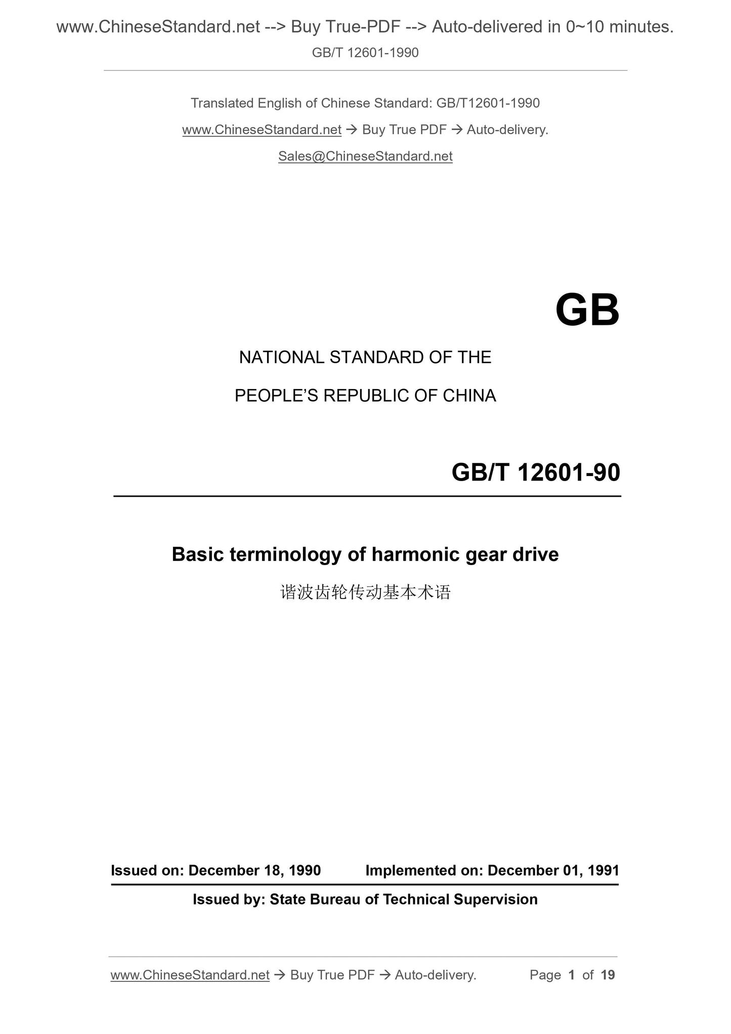
GB/T 12601-1990
GB
NATIONAL STANDARD OF THE
PEOPLE’S REPUBLIC OF CHINA
GB/T 12601-90
Basic terminology of harmonic gear drive
ISSUED ON: DECEMBER 18, 1990
IMPLEMENTED ON: DECEMBER 01, 1991
Issued by: State Bureau of Technical Supervision
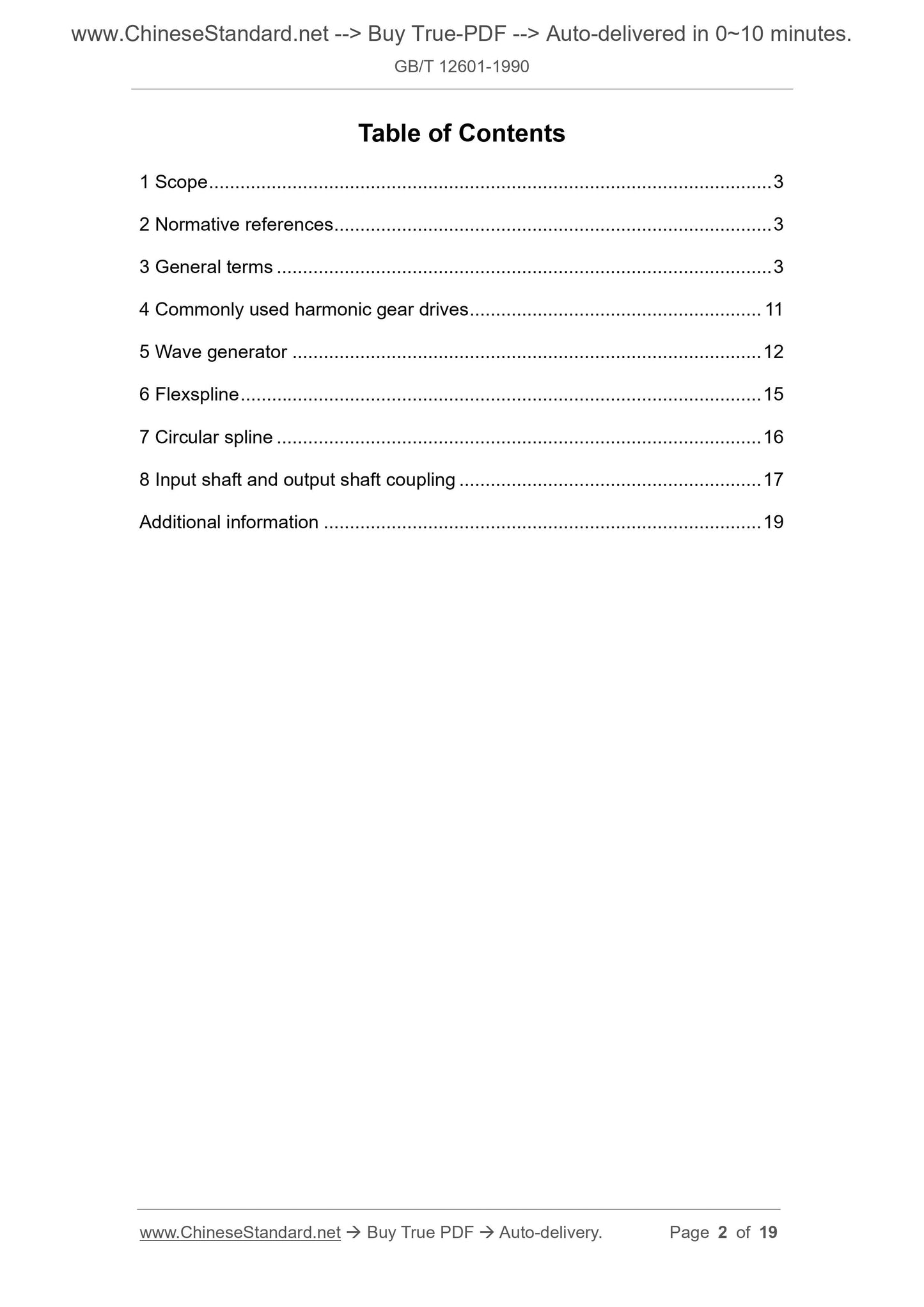
Table of Contents
1 Scope ... 3
2 Normative references ... 3
3 General terms ... 3
4 Commonly used harmonic gear drives ... 11
5 Wave generator ... 12
6 Flexspline ... 15
7 Circular spline ... 16
8 Input shaft and output shaft coupling ... 17
Additional information ... 19
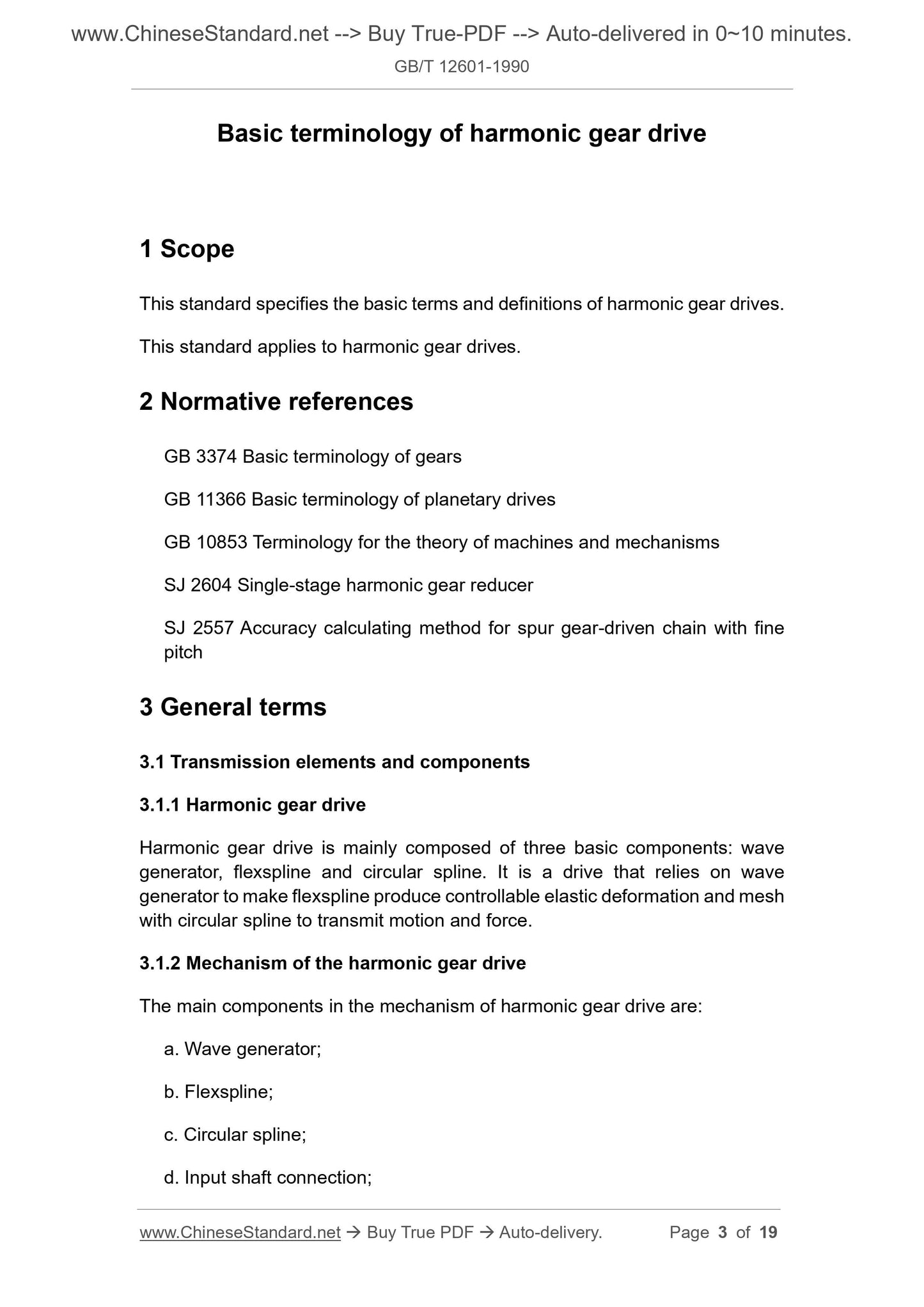
Basic terminology of harmonic gear drive
1 Scope
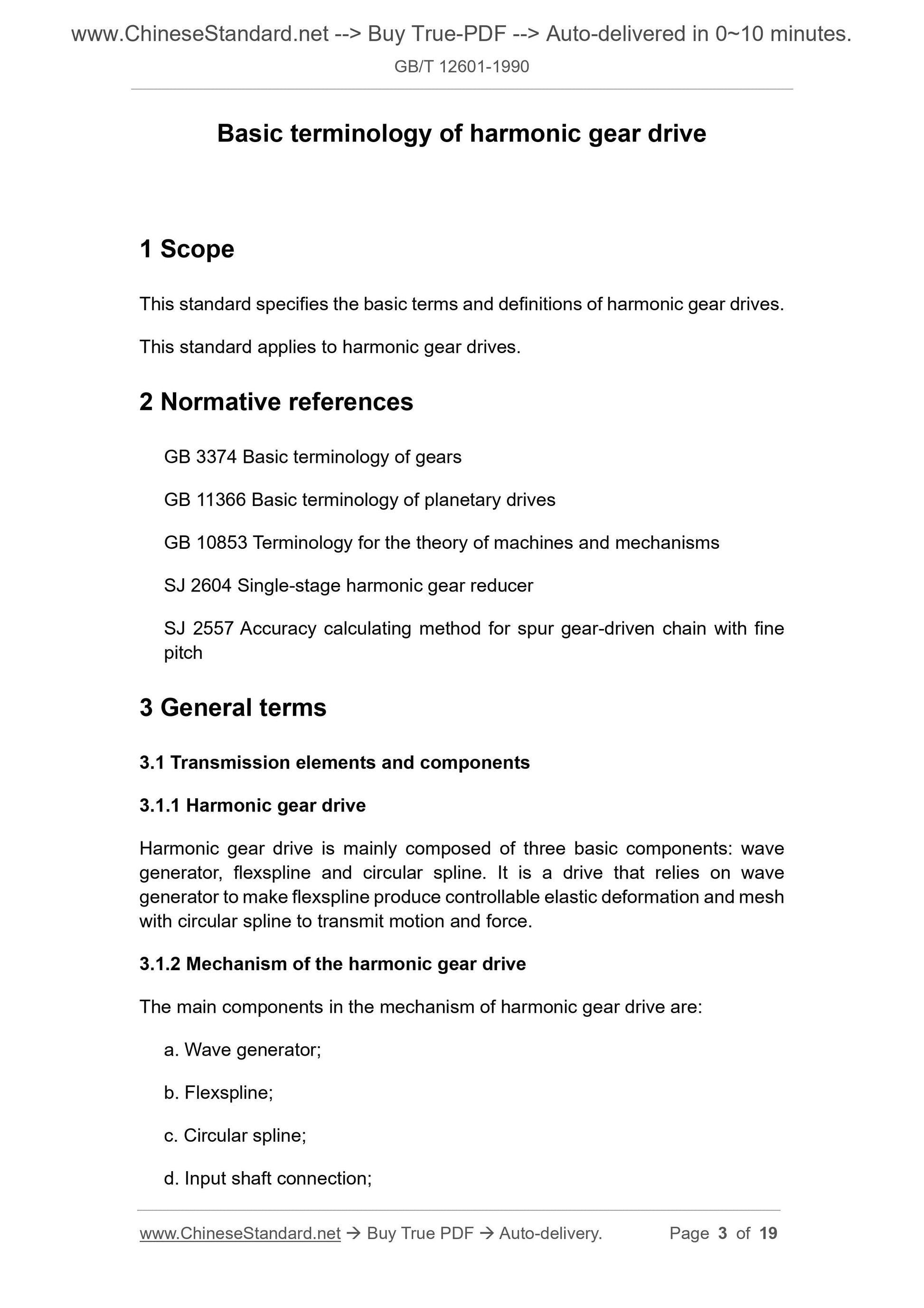
This standard specifies the basic terms and definitions of harmonic gear drives.
This standard applies to harmonic gear drives.
2 Normative references
GB 3374 Basic terminology of gears
GB 11366 Basic terminology of planetary drives
GB 10853 Terminology for the theory of machines and mechanisms
SJ 2604 Single-stage harmonic gear reducer
SJ 2557 Accuracy calculating method for spur gear-driven chain with fine
pitch
3 General terms
3.1 Transmission elements and components
3.1.1 Harmonic gear drive
Harmonic gear drive is mainly composed of three basic components: wave
generator, flexspline and circular spline. It is a drive that relies on wave
generator to make flexspline produce controllable elastic deformation and mesh
with circular spline to transmit motion and force.
3.1.2 Mechanism of the harmonic gear drive
The main components in the mechanism of harmonic gear drive are:
a. Wave generator;
b. Flexspline;
c. Circular spline;
d. Input shaft connection;
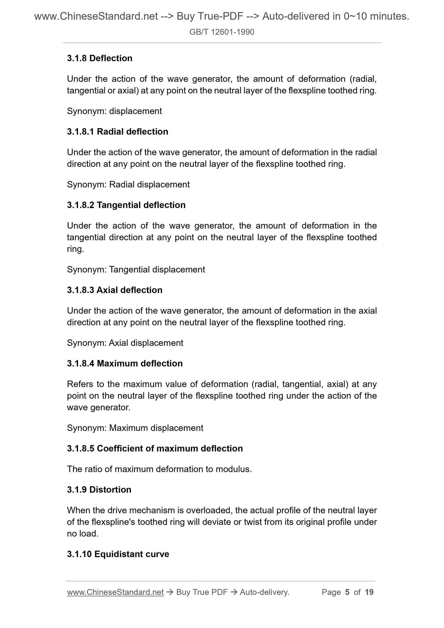
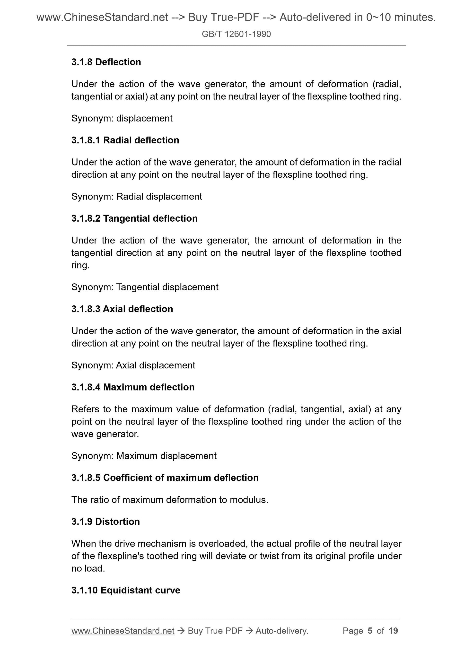
3.1.8 Deflection
Under the action of the wave generator, the amount of deformation (radial,
tangential or axial) at any point on the neutral layer of the flexspline toothed ring.
Synonym: displacement
3.1.8.1 Radial deflection
Under the action of the wave generator, the amount of deformation in the radial
direction at any point on the neutral layer of the flexspline toothed ring.
Synonym: Radial displacement
3.1.8.2 Tangential deflection
Under the action of the wave generator, the amount of deformation in the
tangential direction at any point on the neutral layer of the flexspline toothed
ring.
Synonym: Tangential displacement
3.1.8.3 Axial deflection
Under the action of the wave generator, the amount of deformation in the axial
direction at any point on the neutral layer of the flexspline toothed ring.
Synonym: Axial displacement
3.1.8.4 Maximum deflection
Refers to the maximum value of deformation (radial, tangential, axial) at any
point on the neutral layer of the flexspline toothed ring under the action of the
wave generator.
Synonym: Maximum displacement
3.1.8.5 Coefficient of maximum deflection
The ratio of maximum deformation to modulus.
3.1.9 Distortion
When the drive mechanism is overloaded, the actual profile of the neutral layer
of the flexspline's toothed ring will deviate or twist from its original profile under
no load.
3.1.10 Equidistant curve
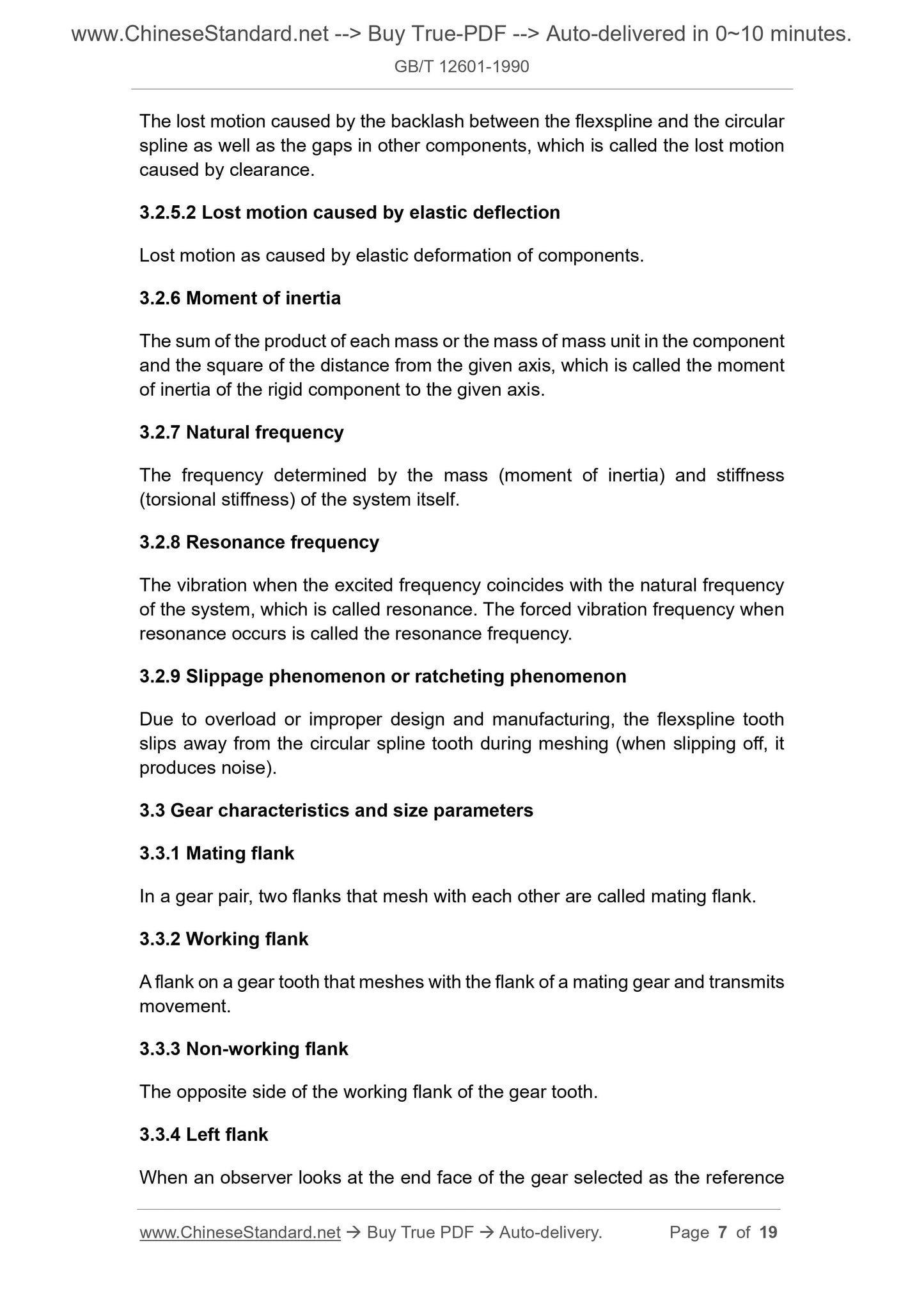
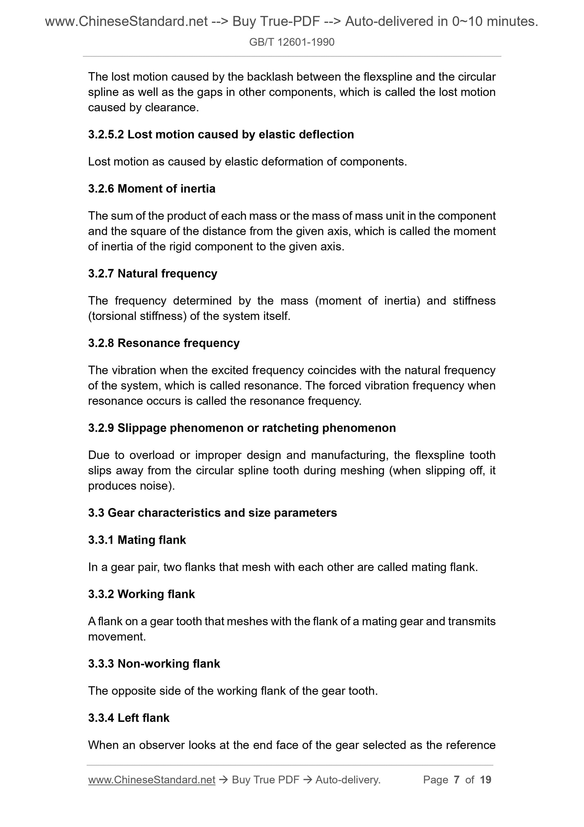
The lost motion caused by the backlash between the flexspline and the circular
spline as well as the gaps in other components, which is called the lost motion
caused by clearance.
3.2.5.2 Lost motion caused by elastic deflection
Lost motion as caused by elastic deformation of components.
3.2.6 Moment of inertia
The sum of the product of each mass or the mass of mass unit in the component
and the square of the distance from the given axis, which is called the moment
of inertia of the rigid component to the given axis.
3.2.7 Natural frequency
The frequency determined by the mass (moment of inertia) and stiffness
(torsional stiffness) of the system itself.
3.2.8 Resonance frequency
The vibration when the excited frequency coincides with the natural frequency
of the system, which is called resonance. The forced vibration frequency when
resonance occurs is called the resonance frequency.
3.2.9 Slippage phenomenon or ratcheting phenomenon
Due to overload or improper design and manufacturing, the flexspline tooth
slips away from the circular spline tooth during meshing (when slipping off, it
produces noise).
3.3 Gear characteristics and size parameters
3.3.1 Mating flank
In a gear pair, two flanks that mesh with each other are called mating flank.
3.3.2 Working flank
A flank on a gear tooth that meshes with the flank of a mating gear and transmits
movement.
3.3.3 Non-working flank
The opposite side of the working flank of the gear tooth.
3.3.4 Left flank
When an observer looks at the end face of the gear selected as the reference
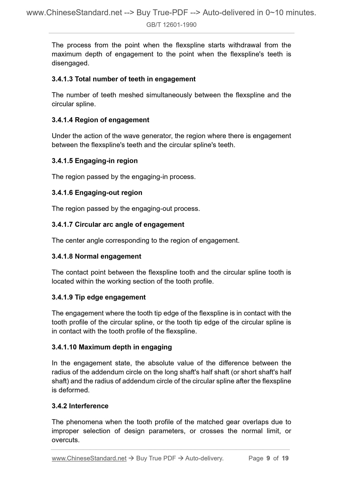
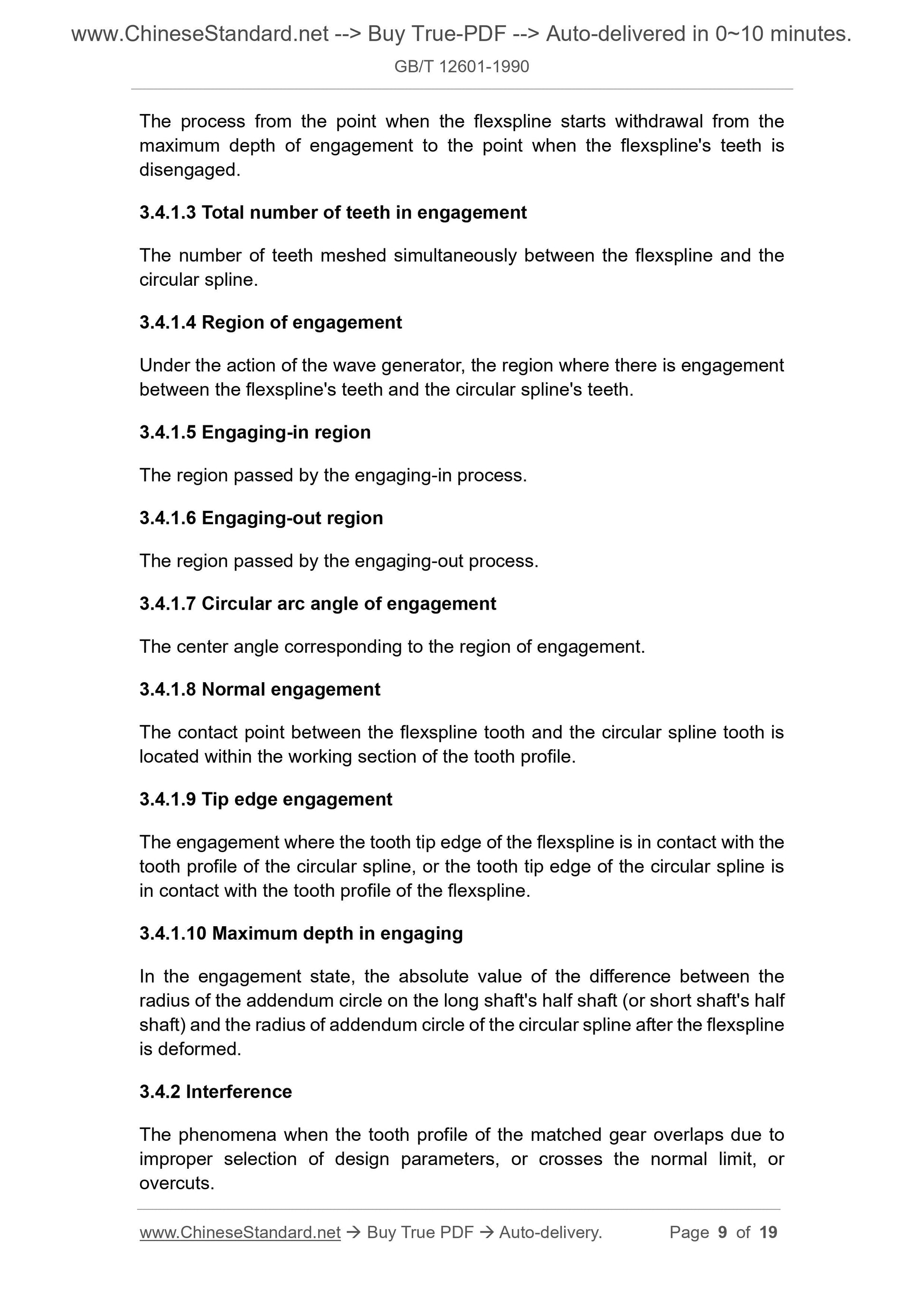
The process from the point when the flexspline starts withdrawal from the
maximum depth of engagement to the point when the flexspline's teeth is
disengaged.
3.4.1.3 Total number of teeth in engagement
The number of teeth meshed simultaneously between the flexspline and the
circular spline.
3.4.1.4 Region of engagement
Under the action of the wave generator, the region where there is engagement
between the flexspline's teeth and the circular spline's teeth.
3.4.1.5 Engaging-in region
The region passed by the engaging-in process.
3.4.1.6 Engaging-out region
The region passed by the engaging-out process.
3.4.1.7 Circular arc angle of engagement
The center angle corresponding to the region of engagement.
3.4.1.8 Normal engagement
The contact point between the flexspline tooth and the circular spline tooth is
located within the working section of the tooth profile.
3.4.1.9 Tip edge engagement
The engagement where the tooth tip edge of the flexspline is in contact with the
tooth profile of the circular spline, or the tooth tip edge of the circular spline is
in contact with the tooth profile of the flexspline.
3.4.1.10 Maximum depth in engaging
In the engagement state, the absolute value of the difference between the
radius of the addendum circle on the long shaft's half shaft (or short shaft's half
shaft) and the radius of addendum circle of the circular spline after the flexspline
is deformed.
3.4.2 Interference
The phenomena when the tooth profile of the matched gear overlaps due to
improper selection of design parameters, or crosses the normal limit, or
overcuts.
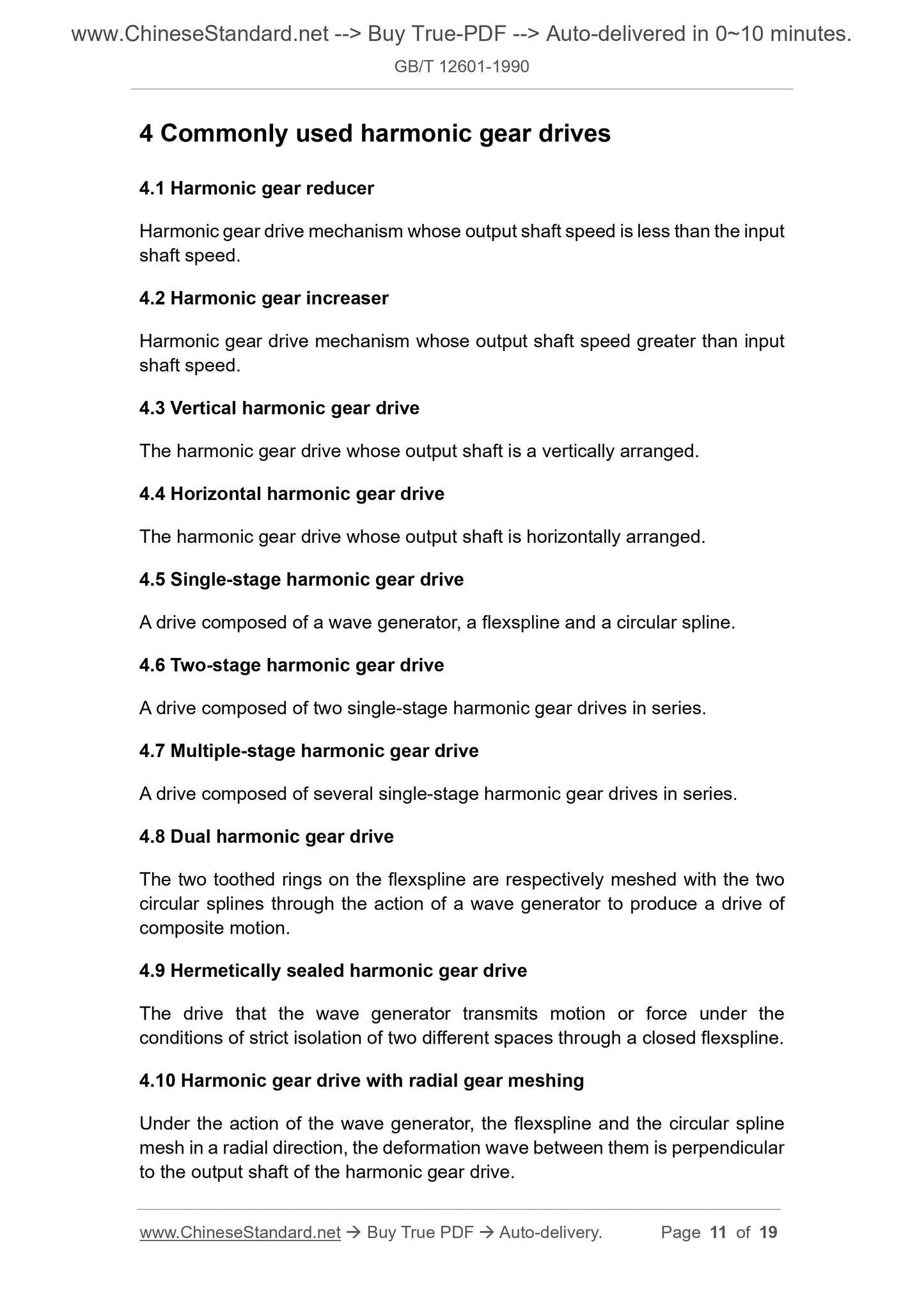
4 Commonly used harmonic gear drives
4.1 Harmonic gear reducer
Harmonic gear drive mechanism whose output shaft speed is less than the input
shaft speed.
4.2 Harmonic gear increaser
Harmonic gear drive mechanism whose output shaft speed greater than input
shaft speed.
4.3 Vertical harmonic gear drive
The harmonic gear drive whose output shaft is a vertically arranged.
4.4 Horizontal harmonic gear drive
The harmonic gear drive whose output shaft is horizontally arranged.
4.5 Single-stage harmonic gear drive
A drive composed of a wave generator, a flexspline and a circular spline.
4.6 Two-stage harmonic gear drive
A drive composed of two single-stage harmonic gear drives in series.
4.7 Multiple-stage harmonic gear drive
A drive composed of several single-stage harmonic gear drives in series.
4.8 Dual harmonic gear drive
The two toothed rings on the flexspline are respectively meshed with the two
circular splines through the action of a wave generator to produce a drive of
composite motion.
4.9 Hermetically sealed harmonic gear drive
The drive that the wave generator transmits motion or force under the
conditions of strict isolation of two different spaces through a closed flexspline.
4.10 Harmonic gear drive with radial gear meshing
Under the action of the wave generator, the flexspline and the circular spline
mesh in a radial direction, the deformation wave between them is perpendicular
to the output shaft of the harmonic gear drive.
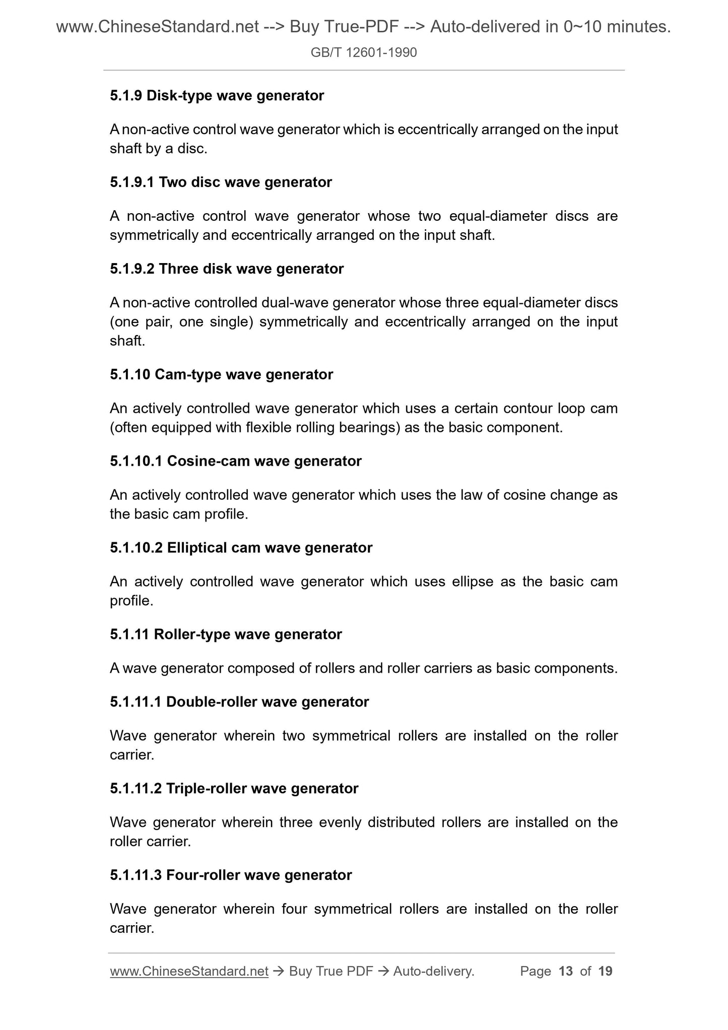
5.1.9 Disk-type wave generator
A non-active control wave generator which is eccentrically arranged on the input
shaft by a disc.
5.1.9.1 Two disc wave generator
A non-active control wave generator whose two equal-diameter discs are
symmetrically and eccentrically arranged on the input shaft.
5.1.9.2 Three disk wave generator
A non-active controlled dual-wave generator whose three equal-diameter discs
(one pair, one single) symmetrically and eccentrically arranged on the input
shaft.
5.1.10 Cam-type wave generator
An actively controlled wave generator which uses a certain contour loop cam
(often equipped with flexible rolling bearings) as the basic component.
5.1.10.1 Cosine-cam wave generator
An actively controlled wave generator which uses the law of cosine change as
the basic cam profile.
5.1.10.2 Elliptical cam wave generator
An actively controlled wave generator which uses ellipse as the basic cam
profile.
5.1.11 Roller-type wave generator
A wave generator composed of rollers and roller carriers as basic components.
5.1.11.1 Double-roller wave generator
Wave generator wherein two symmetrical rollers are installed on the roller
carrier.
5.1.11.2 Triple-roller wave generator
Wave generator wherein three evenly distributed rollers are installed on the
roller carrier.
5.1.11.3 Four-roller wave generator
Wave generator wherein four symmetrical rollers are installed on the roller
carrier.
5.2.5 Angle of contact
The angle at which the disc of the disc wave generator fits the inner surface of
the flexspline.
6 Flexspline
6.1 Types of flexsplines
6.1.1 Cylindrical tube-shape flexspline
The flexspline whose basic shape is cylindrical.
6.1.2 Ring-shape flexspline
The flexspline whose basic shape is ring.
6.1.3 Cup-shape flexspline
The flexspline whose basic shape is a cylindrical cup.
6.1.4 Bell-shape flexspline
The flexspline whose basic shape is an ancient bell.
6.1.5 Double bell-shape flexspline
The flexspline whose basic shape is approximately the shape of a single leaf
hyperboloid.
6.1.6 Flexspline’s toothed ring
The part on the flexspline with gear teeth.
6.1.7 Lining ring
A thin-walled ring arranged between the wave generator and the inner surface
of the flexspline's toothed ring.
6.2 Geometric elements
6.2.1 Neutral layer of flexspline’s toothed ring
The layer, which is set in the flexspline’s toothed ring, bisect the curved surface
where the distance from the tooth root to the inner wall of the flexspline is
located.
6.2.2 Original curve of neutral layer of flexspline's toothed ring
7.1.2 External circular spline
The external gear.
7.2 Geometric elements
7.2.1 Beginning circle of involute profile on external circular spline
A circle with an involute profile on the external circular spline tooth profile close
to the tooth root.
7.2.2 Terminal circle of involute profile on internal circular spline
The circle that terminates the involute tooth profile on the tooth profile of the
internal circular spline close to the tooth root.
8 Input shaft and output shaft coupling
8.1 Coupling of wave generator and input shaft
8.1.1 Elastic coupling
Coupling form which is flexible.
8.1.2 Rigid coupling
Coupling form which is rigid.
8.1.3 Oldham coupling
The input shaft and the wave generator are connected by a cross Oldham.
8.2 Coupling of flexspline and output shaft
8.2.1 Integrated coupling
The bottom of the flexspline is coupled to the output coupling plate by screw or
welding.
8.2.2 Dynamic coupling
The coupling method that the wall of the flexspline cylinder and the output
coupling disc form synchronous meshing motion by the inner and outer toothed
rings with the same number of teeth.
8.2.3 Splined coupling
The coupling form that the wall of the flexspline cylinder is coupled with the
GB/T 12601-1990
GB
NATIONAL STANDARD OF THE
PEOPLE’S REPUBLIC OF CHINA
GB/T 12601-90
Basic terminology of harmonic gear drive
ISSUED ON: DECEMBER 18, 1990
IMPLEMENTED ON: DECEMBER 01, 1991
Issued by: State Bureau of Technical Supervision
Table of Contents
1 Scope ... 3
2 Normative references ... 3
3 General terms ... 3
4 Commonly used harmonic gear drives ... 11
5 Wave generator ... 12
6 Flexspline ... 15
7 Circular spline ... 16
8 Input shaft and output shaft coupling ... 17
Additional information ... 19
Basic terminology of harmonic gear drive
1 Scope
This standard specifies the basic terms and definitions of harmonic gear drives.
This standard applies to harmonic gear drives.
2 Normative references
GB 3374 Basic terminology of gears
GB 11366 Basic terminology of planetary drives
GB 10853 Terminology for the theory of machines and mechanisms
SJ 2604 Single-stage harmonic gear reducer
SJ 2557 Accuracy calculating method for spur gear-driven chain with fine
pitch
3 General terms
3.1 Transmission elements and components
3.1.1 Harmonic gear drive
Harmonic gear drive is mainly composed of three basic components: wave
generator, flexspline and circular spline. It is a drive that relies on wave
generator to make flexspline produce controllable elastic deformation and mesh
with circular spline to transmit motion and force.
3.1.2 Mechanism of the harmonic gear drive
The main components in the mechanism of harmonic gear drive are:
a. Wave generator;
b. Flexspline;
c. Circular spline;
d. Input shaft connection;
3.1.8 Deflection
Under the action of the wave generator, the amount of deformation (radial,
tangential or axial) at any point on the neutral layer of the flexspline toothed ring.
Synonym: displacement
3.1.8.1 Radial deflection
Under the action of the wave generator, the amount of deformation in the radial
direction at any point on the neutral layer of the flexspline toothed ring.
Synonym: Radial displacement
3.1.8.2 Tangential deflection
Under the action of the wave generator, the amount of deformation in the
tangential direction at any point on the neutral layer of the flexspline toothed
ring.
Synonym: Tangential displacement
3.1.8.3 Axial deflection
Under the action of the wave generato...
Share
