1
/
of
9
www.ChineseStandard.us -- Field Test Asia Pte. Ltd.
GB/T 12673-2019 English PDF (GB/T12673-2019)
GB/T 12673-2019 English PDF (GB/T12673-2019)
Regular price
$455.00
Regular price
Sale price
$455.00
Unit price
/
per
Shipping calculated at checkout.
Couldn't load pickup availability
GB/T 12673-2019: Motor vehicle main dimensions measurement method
Delivery: 9 seconds. Download (& Email) true-PDF + Invoice.
Get Quotation: Click GB/T 12673-2019 (Self-service in 1-minute)
Historical versions (Master-website): GB/T 12673-2019
Preview True-PDF (Reload/Scroll-down if blank)
GB/T 12673-2019
NATIONAL STANDARD OF THE
PEOPLE’S REPUBLIC OF CHINA
ICS 43.020
T 04
Replacing GB/T 12673-1990
Motor vehicle main dimensions measurement method
ISSUED ON: OCTOBER 18, 2019
IMPLEMENTED ON: MAY 01, 2020
Issued by: State Administration for Market Regulation;
Standardization Administration of the People’s Republic of
China.
Table of Contents
Foreword ... 3
1 Scope ... 5
2 Normative references ... 5
3 Terms and definitions ... 5
4 Measurement preparation ... 17
5 Dimension codes ... 19
6 Determination of the zero plane and the base point ... 21
7 Dimension codes, name and measurement methods of internal dimensions
... 24
8 Dimension codes, name and measurement methods of external dimensions
... 47
9 Dimension codes, name and measurement methods of luggage
compartment/ cargo dimension ... 55
Appendix A (Informative) Driver and passenger head contour and positioning
... 66
Appendix B (Normative) H-point travel path ... 72
Appendix C (Normative) Structural diagram of seat type determination method
and L48, L51 measurement method ... 74
Appendix D (Informative) Figures ... 76
Motor vehicle main dimensions measurement method
1 Scope
This Standard specifies motor vehicle main dimensions measurement method.
The external dimensions and luggage/ cargo dimensions measurement
methods that are specified in this Standard are applicable to M and N vehicles;
other vehicles can implement by reference.
The internal dimensions measurement methods that are specified in this
Standard are applicable to M1 vehicles; other vehicles can implement by
reference.
2 Normative references
The following documents are indispensable for the application of this document.
For dated references, only the dated version applies to this document. For
undated references, the latest edition (including all amendments) applies to this
document.
GB 1589, Limits of dimensions, axle load and masses for motor vehicles,
trailers and combination vehicles
GB/T 3730.2, Road vehicle – Masses - Vocabulary and codes
GB/T 3730.3-1992, Motor vehicles and towed vehicles - Dimensions of
vehicles - Terms and definitions
GB/T 19514, Passenger cars - Luggage compartments - Method of
measuring reference volume
GB/T 29120-2012, Procedure for H-point and R-point determination
3 Terms and definitions
Terms and definitions determined by GB 1589, GB/T 3730.2, GB/T 3730.3-1992,
GB/T 29120-2012, and the following ones are applicable to this document. For
ease of use, some of the terms and definitions in GB/T 29120-2012 are
repeated below.
3.1 Vehicle coordinate system
In HPM, the seat is located at the ride base point that is specified by the
manufacturer. When HPM uses the appropriate leg length, measure the H-point
at the hinge center of its torso line and thigh bar centerline. In HPM-II, the seat
is located at the ride base point that is specified by the manufacturer. When
HPM-II adopts a proper posture, measure the H-point at the hinge center point
of its seat plate assembly and back plate assembly.
[GB/T 29120-2012, Definition 3.3.2]
3.2.3 R-point
The designed H-point position that is set by the manufacturer, which is
specifically designated as the R-point or SgRP and meets all the following
requirements:
a) the basic base point that is used to establish passenger adjustment tools
and dimensions;
b) simulate the hinge center position of the human torso and thigh;
c) have a coordinate that is established relative to the structure of the
designed vehicle;
d) establish the rear end of each designated seating position or the H-point
of the normal driving and seating positions that are designated by the
manufacturer, which takes into account all the adjustment states of the
seat, including horizontal, vertical and tilt, but does not include seat
movement that is used for abnormal driving or seating purposes.
3.2.4 H-point travel path
All possible positions of H-point under all adjustment states (including horizontal,
vertical and tilt) of the specified seating position.
[GB/T 29120-2012, Definition 3.9]
3.2.5 Three-dimensional H-point machine; HPM
The device that is used to measure the actual H-point and the actual torso angle
on a vehicle.
[GB/T 29120-2012, Definition 3.1]
3.2.6 Three-dimensional H-point machine-II; HPM-II
The new SAE (Society of Automotive Engineers) H-point machine that is used
to more accurately determine the actual H-point, actual torso angle and other
parameter values on a vehicle. The main change of HPM-II is the improved
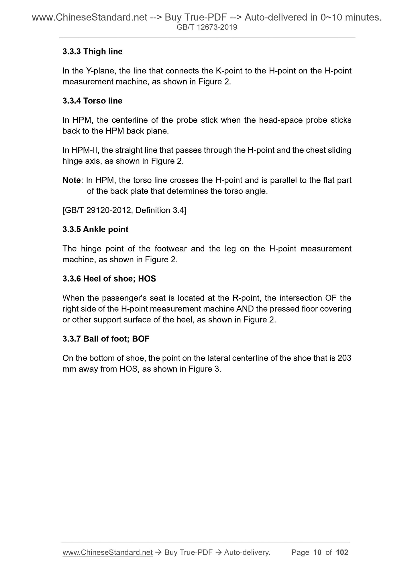
3.3.3 Thigh line
In the Y-plane, the line that connects the K-point to the H-point on the H-point
measurement machine, as shown in Figure 2.
3.3.4 Torso line
In HPM, the centerline of the probe stick when the head-space probe sticks
back to the HPM back plane.
In HPM-II, the straight line that passes through the H-point and the chest sliding
hinge axis, as shown in Figure 2.
Note: In HPM, the torso line crosses the H-point and is parallel to the flat part
of the back plate that determines the torso angle.
[GB/T 29120-2012, Definition 3.4]
3.3.5 Ankle point
The hinge point of the footwear and the leg on the H-point measurement
machine, as shown in Figure 2.
3.3.6 Heel of shoe; HOS
When the passenger's seat is located at the R-point, the intersection OF the
right side of the H-point measurement machine AND the pressed floor covering
or other support surface of the heel, as shown in Figure 2.
3.3.7 Ball of foot; BOF
On the bottom of shoe, the point on the lateral centerline of the shoe that is 203
mm away from HOS, as shown in Figure 3.
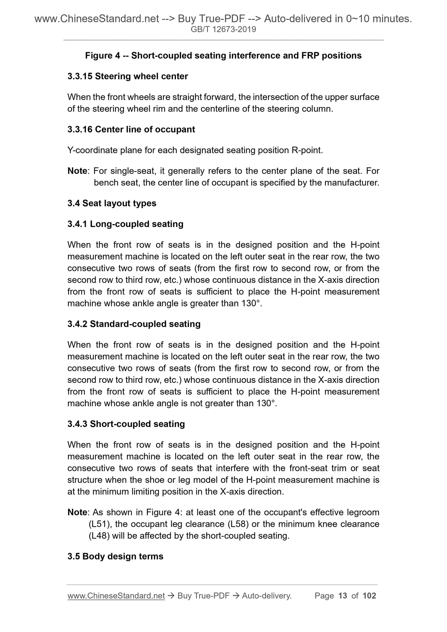
Figure 4 -- Short-coupled seating interference and FRP positions
3.3.15 Steering wheel center
When the front wheels are straight forward, the intersection of the upper surface
of the steering wheel rim and the centerline of the steering column.
3.3.16 Center line of occupant
Y-coordinate plane for each designated seating position R-point.
Note: For single-seat, it generally refers to the center plane of the seat. For
bench seat, the center line of occupant is specified by the manufacturer.
3.4 Seat layout types
3.4.1 Long-coupled seating
When the front row of seats is in the designed position and the H-point
measurement machine is located on the left outer seat in the rear row, the two
consecutive two rows of seats (from the first row to second row, or from the
second row to third row, etc.) whose continuous distance in the X-axis direction
from the front row of seats is sufficient to place the H-point measurement
machine whose ankle angle is greater than 130°.
3.4.2 Standard-coupled seating
When the front row of seats is in the designed position and the H-point
measurement machine is located on the left outer seat in the rear row, the two
consecutive two rows of seats (from the first row to second row, or from the
second row to third row, etc.) whose continuous distance in the X-axis direction
from the front row of seats is sufficient to place the H-point measurement
machine whose ankle angle is not greater than 130°.
3.4.3 Short-coupled seating
When the front row of seats is in the designed position and the H-point
measurement machine is located on the left outer seat in the rear row, the
consecutive two rows of seats that interfere with the front-seat trim or seat
structure when the shoe or leg model of the H-point measurement machine is
at the minimum limiting position in the X-axis direction.
Note: As shown in Figure 4: at least one of the occupant's effective legroom
(L51), the occupant leg clearance (L58) or the minimum knee clearance
(L48) will be affected by the short-coupled seating.
3.5 Body design terms
4.2.4 Unless otherwise specified, when the motor vehicle is equipped with
adjustable or movable parts, it shall be measured in the following prescribed
state:
a) The cargo fence shall be closed;
b) The doors, engine hood, luggage compartment cover and vent cover are
all closed;
c) The radio antenna shall be retracted;
d) It excludes the car license plate, but includes the car license plate holder
(frame);
e) If the steering wheel is adjustable, it shall be adjusted to the position that
is specified by the manufacturer; if it is not specified by the manufacturer,
it shall be adjusted to the middle position of the adjustable range;
f) The vehicle pedal shall be in the free position; for adjustable pedal, it shall
be adjusted to the maximum or forward position that is specified by the
manufacturer;
g) The vehicle seats shall be adjusted as follows:
1) For height-adjustable headrests, unless otherwise specified, it shall be
adjusted to the highest position;
2) If the seat is adjustable horizontally and vertically, it shall be adjusted
to the R-point or the position that is specified by the manufacturer;
3) If the backrest is adjustable, it shall be adjusted to the fully retracted
position;
4) If the cushion angle is adjustable, it shall be adjusted to the angle that
is specified by the manufacturer;
5) If the seat back angle is adjustable, the first row of seats shall be
adjusted to 22° or the angle that is specified by the manufacturer; the
second and third rows of seats shall be adjusted to 25° or the angle that
is specified by the manufacturer;
h) If other parts are adjustable, they shall be adjusted to the position that is
specified by the manufacturer.
4.3 Measurement benchmark
4.3.1 Unless otherwise specified, the length shall be measured on a straight
line parallel to the X-axis direction; the width shall be measured on a straight
line parallel to the Y-axis direction; the height shall be measured on a straight
line parallel to the Z-axis direction.
4.3.2 If the sides of the vehicle are symmetrical, measure only the left or right
side.
4.3.3 Unless otherwise specified, the internal dimensions of the vehicle shall be
measured on the center line of occupant. When the H-point measurement
machine is used for measurement, it should use HPM-II, and the leg length
should be adjusted to the position of the 95th percentile. In order to make the
measurements consistent, it should use the formula for the H-point travel path
of the seat that is given in Appendix B.
4.3.4 For the determination methods of the long-coupled, standard-coupled and
short-coupled seating types, see Appendix C. During the measurement of long-
coupled and standard-coupled seating, the H-point measurement machine is
recommended to use the 95th percentile; other types can be specified by the
manufacturer.
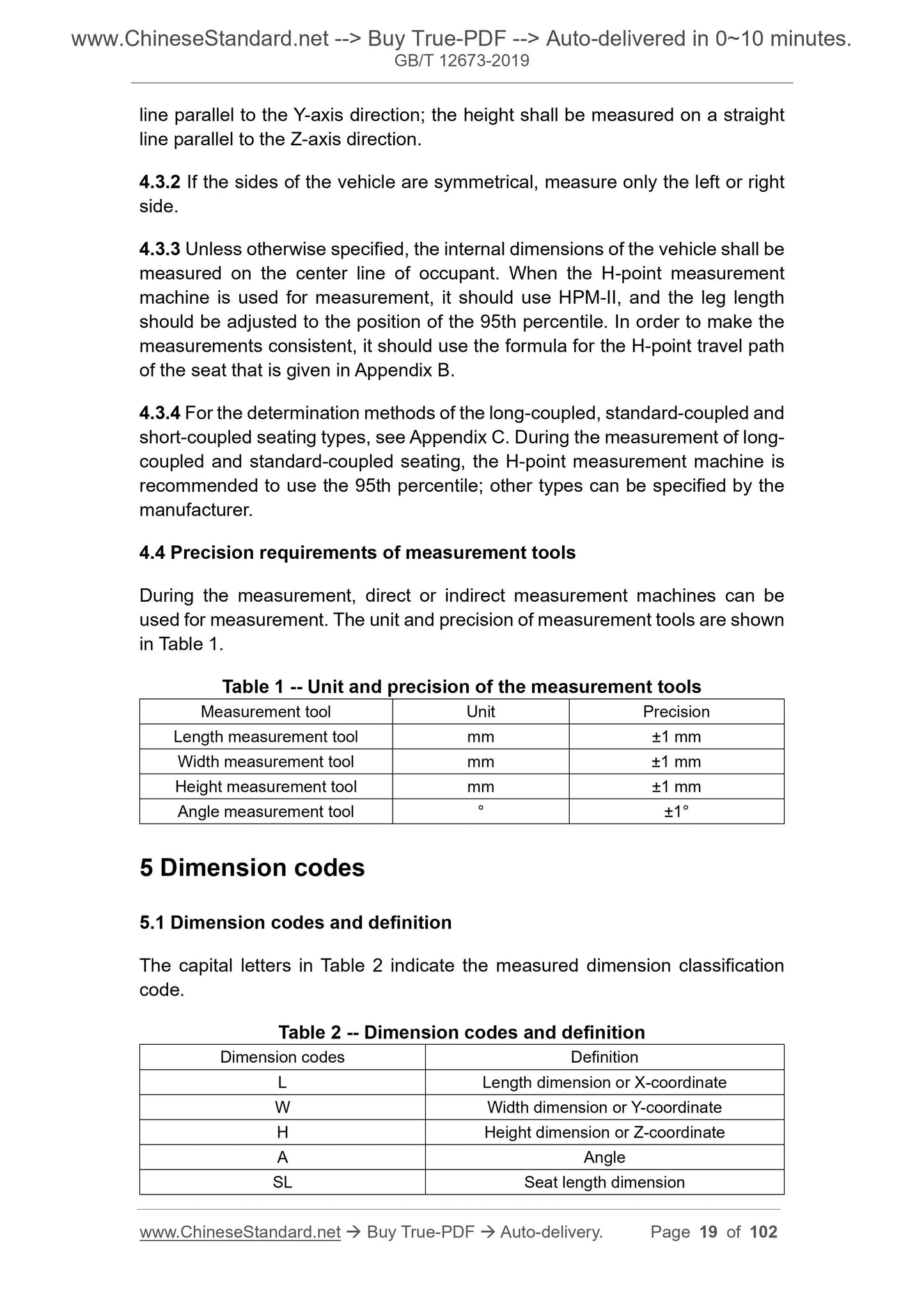
4.4 Precision requirements of measurement tools
During the measurement, direct or indirect measurement machines can be
used for measurement. The unit and precision of measurement tools are shown
in Table 1.
Table 1 -- Unit and precision of the measurement tools
Measurement tool Unit Precision
Length measurement tool mm ±1 mm
Width measurement tool mm ±1 mm
Height measurement tool mm ±1 mm
Angle measurement tool ° ±1°
5 Dimension codes
5.1 Dimension codes and definition
The capital letters in Table 2 indicate the measured dimension classification
code.
Table 2 -- Dimension codes and definition
Dimension codes Definition
L Length dimension or X-coordinate
W Width dimension or Y-coordinate
H Height dimension or Z-coordinate
A Angle
SL Seat length dimension
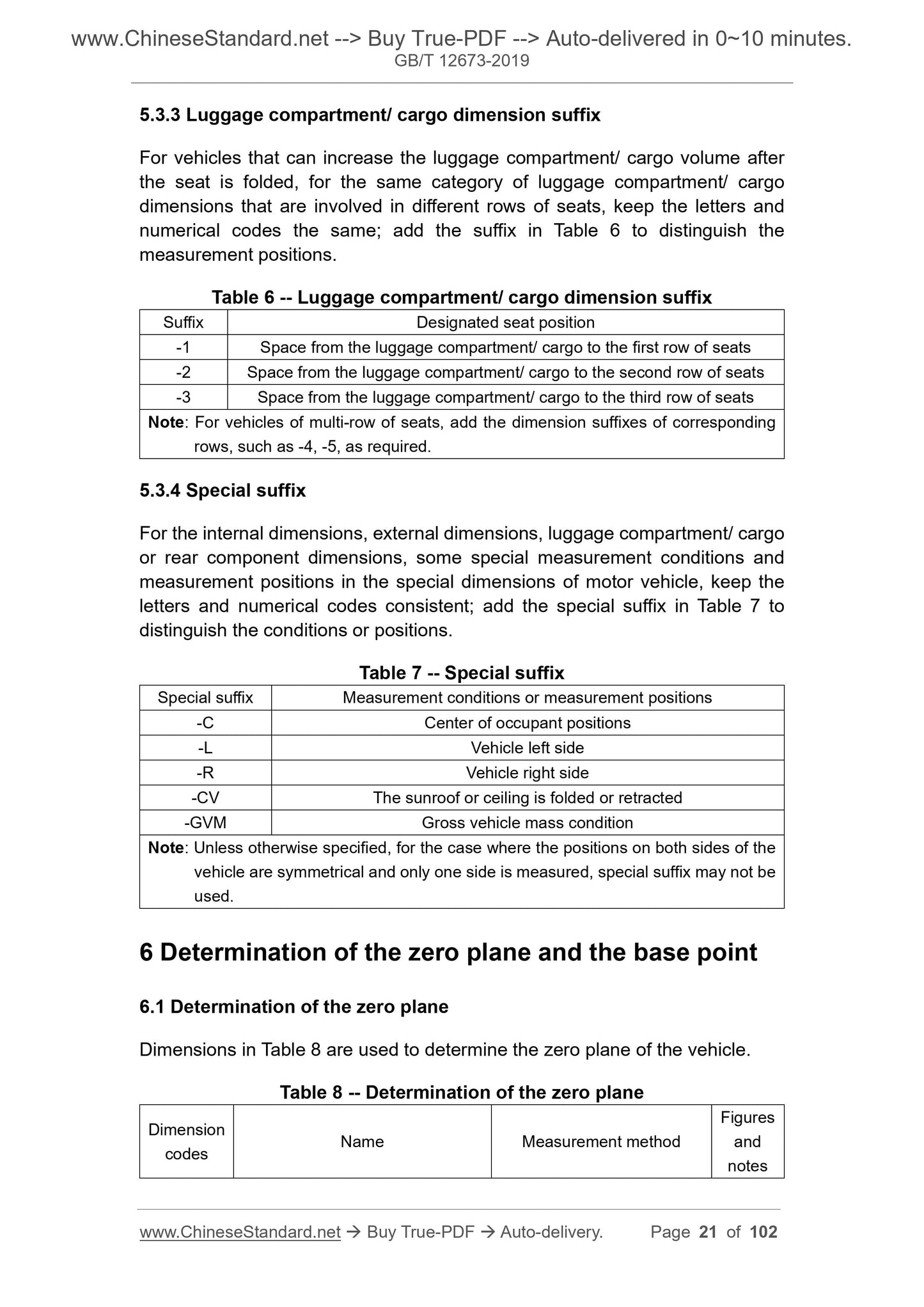
5.3.3 Luggage compartment/ cargo dimension suffix
For vehicles that can increase the luggage compartment/ cargo volume after
the seat is folded, for the same category of luggage compartment/ cargo
dimensions that are involved in different rows of seats, keep the letters and
numerical codes the same; add the suffix in Table 6 to distinguish the
measurement positions.
Table 6 -- Luggage compartment/ cargo dimension suffix
Suffix Designated seat position
-1 Space from the luggage compartment/ cargo to the first row of seats
-2 Space from the luggage compartment/ cargo to the second row of seats
-3 Space from the luggage compartment/ cargo to the third row of seats
Note: For vehicles of multi-row of seats, add the dimension suffixes of corresponding
rows, such as -4, -5, as required.
5.3.4 Special suffix
For the internal dimensions, external dimensions, luggage compartment/ cargo
or rear component dimensions, some special measurement conditions and
measurement positions in the special dimensions of motor vehicle, keep the
letters and numerical codes consistent; add the special suffix in Table 7 to
distinguish the conditions or positions.
Table 7 -- Special suffix
Special suffix Measurement conditions or measurement positions
-C Center of occupant positions
-L Vehicle left side
-R Vehicle right side
-CV The sunroof or ceiling is folded or retracted
-GVM Gross vehicle mass condition
Note: Unless otherwise specified, for the case where the positions on both sides of the
vehicle are symmetrical and only one side is measured, special suffix may not be
used.
6 Determination of the zero plane and the base point
6.1 Determination of the zero plane
Dimensions in Table 8 are used to determine the zero plane of the vehicle.
Table 8 -- Determination of the zero plane
Dimension
codes Name Measurement method
Figures
and
notes
GB/T 12673-2019
NATIONAL STANDARD OF THE
PEOPLE’S REPUBLIC OF CHINA
ICS 43.020
T 04
Replacing GB/T 12673-1990
Motor vehicle main dimensions measurement method
ISSUED ON: OCTOBER 18, 2019
IMPLEMENTED ON: MAY 01, 2020
Issued by: State Administration for Market Regulation;
Standardization Administration of the People’s Republic of
China.
Table of Contents
Foreword ... 3
1 Scope ... 5
2 Normative references ... 5
3 Terms and definitions ... 5
4 Measurement preparation ... 17
5 Dimension codes ... 19
6 Determination of the zero plane and the base point ... 21
7 Dimension codes, name and measurement methods of int...
Delivery: 9 seconds. Download (& Email) true-PDF + Invoice.
Get Quotation: Click GB/T 12673-2019 (Self-service in 1-minute)
Historical versions (Master-website): GB/T 12673-2019
Preview True-PDF (Reload/Scroll-down if blank)
GB/T 12673-2019
NATIONAL STANDARD OF THE
PEOPLE’S REPUBLIC OF CHINA
ICS 43.020
T 04
Replacing GB/T 12673-1990
Motor vehicle main dimensions measurement method
ISSUED ON: OCTOBER 18, 2019
IMPLEMENTED ON: MAY 01, 2020
Issued by: State Administration for Market Regulation;
Standardization Administration of the People’s Republic of
China.
Table of Contents
Foreword ... 3
1 Scope ... 5
2 Normative references ... 5
3 Terms and definitions ... 5
4 Measurement preparation ... 17
5 Dimension codes ... 19
6 Determination of the zero plane and the base point ... 21
7 Dimension codes, name and measurement methods of internal dimensions
... 24
8 Dimension codes, name and measurement methods of external dimensions
... 47
9 Dimension codes, name and measurement methods of luggage
compartment/ cargo dimension ... 55
Appendix A (Informative) Driver and passenger head contour and positioning
... 66
Appendix B (Normative) H-point travel path ... 72
Appendix C (Normative) Structural diagram of seat type determination method
and L48, L51 measurement method ... 74
Appendix D (Informative) Figures ... 76
Motor vehicle main dimensions measurement method
1 Scope
This Standard specifies motor vehicle main dimensions measurement method.
The external dimensions and luggage/ cargo dimensions measurement
methods that are specified in this Standard are applicable to M and N vehicles;
other vehicles can implement by reference.
The internal dimensions measurement methods that are specified in this
Standard are applicable to M1 vehicles; other vehicles can implement by
reference.
2 Normative references
The following documents are indispensable for the application of this document.
For dated references, only the dated version applies to this document. For
undated references, the latest edition (including all amendments) applies to this
document.
GB 1589, Limits of dimensions, axle load and masses for motor vehicles,
trailers and combination vehicles
GB/T 3730.2, Road vehicle – Masses - Vocabulary and codes
GB/T 3730.3-1992, Motor vehicles and towed vehicles - Dimensions of
vehicles - Terms and definitions
GB/T 19514, Passenger cars - Luggage compartments - Method of
measuring reference volume
GB/T 29120-2012, Procedure for H-point and R-point determination
3 Terms and definitions
Terms and definitions determined by GB 1589, GB/T 3730.2, GB/T 3730.3-1992,
GB/T 29120-2012, and the following ones are applicable to this document. For
ease of use, some of the terms and definitions in GB/T 29120-2012 are
repeated below.
3.1 Vehicle coordinate system
In HPM, the seat is located at the ride base point that is specified by the
manufacturer. When HPM uses the appropriate leg length, measure the H-point
at the hinge center of its torso line and thigh bar centerline. In HPM-II, the seat
is located at the ride base point that is specified by the manufacturer. When
HPM-II adopts a proper posture, measure the H-point at the hinge center point
of its seat plate assembly and back plate assembly.
[GB/T 29120-2012, Definition 3.3.2]
3.2.3 R-point
The designed H-point position that is set by the manufacturer, which is
specifically designated as the R-point or SgRP and meets all the following
requirements:
a) the basic base point that is used to establish passenger adjustment tools
and dimensions;
b) simulate the hinge center position of the human torso and thigh;
c) have a coordinate that is established relative to the structure of the
designed vehicle;
d) establish the rear end of each designated seating position or the H-point
of the normal driving and seating positions that are designated by the
manufacturer, which takes into account all the adjustment states of the
seat, including horizontal, vertical and tilt, but does not include seat
movement that is used for abnormal driving or seating purposes.
3.2.4 H-point travel path
All possible positions of H-point under all adjustment states (including horizontal,
vertical and tilt) of the specified seating position.
[GB/T 29120-2012, Definition 3.9]
3.2.5 Three-dimensional H-point machine; HPM
The device that is used to measure the actual H-point and the actual torso angle
on a vehicle.
[GB/T 29120-2012, Definition 3.1]
3.2.6 Three-dimensional H-point machine-II; HPM-II
The new SAE (Society of Automotive Engineers) H-point machine that is used
to more accurately determine the actual H-point, actual torso angle and other
parameter values on a vehicle. The main change of HPM-II is the improved
3.3.3 Thigh line
In the Y-plane, the line that connects the K-point to the H-point on the H-point
measurement machine, as shown in Figure 2.
3.3.4 Torso line
In HPM, the centerline of the probe stick when the head-space probe sticks
back to the HPM back plane.
In HPM-II, the straight line that passes through the H-point and the chest sliding
hinge axis, as shown in Figure 2.
Note: In HPM, the torso line crosses the H-point and is parallel to the flat part
of the back plate that determines the torso angle.
[GB/T 29120-2012, Definition 3.4]
3.3.5 Ankle point
The hinge point of the footwear and the leg on the H-point measurement
machine, as shown in Figure 2.
3.3.6 Heel of shoe; HOS
When the passenger's seat is located at the R-point, the intersection OF the
right side of the H-point measurement machine AND the pressed floor covering
or other support surface of the heel, as shown in Figure 2.
3.3.7 Ball of foot; BOF
On the bottom of shoe, the point on the lateral centerline of the shoe that is 203
mm away from HOS, as shown in Figure 3.
Figure 4 -- Short-coupled seating interference and FRP positions
3.3.15 Steering wheel center
When the front wheels are straight forward, the intersection of the upper surface
of the steering wheel rim and the centerline of the steering column.
3.3.16 Center line of occupant
Y-coordinate plane for each designated seating position R-point.
Note: For single-seat, it generally refers to the center plane of the seat. For
bench seat, the center line of occupant is specified by the manufacturer.
3.4 Seat layout types
3.4.1 Long-coupled seating
When the front row of seats is in the designed position and the H-point
measurement machine is located on the left outer seat in the rear row, the two
consecutive two rows of seats (from the first row to second row, or from the
second row to third row, etc.) whose continuous distance in the X-axis direction
from the front row of seats is sufficient to place the H-point measurement
machine whose ankle angle is greater than 130°.
3.4.2 Standard-coupled seating
When the front row of seats is in the designed position and the H-point
measurement machine is located on the left outer seat in the rear row, the two
consecutive two rows of seats (from the first row to second row, or from the
second row to third row, etc.) whose continuous distance in the X-axis direction
from the front row of seats is sufficient to place the H-point measurement
machine whose ankle angle is not greater than 130°.
3.4.3 Short-coupled seating
When the front row of seats is in the designed position and the H-point
measurement machine is located on the left outer seat in the rear row, the
consecutive two rows of seats that interfere with the front-seat trim or seat
structure when the shoe or leg model of the H-point measurement machine is
at the minimum limiting position in the X-axis direction.
Note: As shown in Figure 4: at least one of the occupant's effective legroom
(L51), the occupant leg clearance (L58) or the minimum knee clearance
(L48) will be affected by the short-coupled seating.
3.5 Body design terms
4.2.4 Unless otherwise specified, when the motor vehicle is equipped with
adjustable or movable parts, it shall be measured in the following prescribed
state:
a) The cargo fence shall be closed;
b) The doors, engine hood, luggage compartment cover and vent cover are
all closed;
c) The radio antenna shall be retracted;
d) It excludes the car license plate, but includes the car license plate holder
(frame);
e) If the steering wheel is adjustable, it shall be adjusted to the position that
is specified by the manufacturer; if it is not specified by the manufacturer,
it shall be adjusted to the middle position of the adjustable range;
f) The vehicle pedal shall be in the free position; for adjustable pedal, it shall
be adjusted to the maximum or forward position that is specified by the
manufacturer;
g) The vehicle seats shall be adjusted as follows:
1) For height-adjustable headrests, unless otherwise specified, it shall be
adjusted to the highest position;
2) If the seat is adjustable horizontally and vertically, it shall be adjusted
to the R-point or the position that is specified by the manufacturer;
3) If the backrest is adjustable, it shall be adjusted to the fully retracted
position;
4) If the cushion angle is adjustable, it shall be adjusted to the angle that
is specified by the manufacturer;
5) If the seat back angle is adjustable, the first row of seats shall be
adjusted to 22° or the angle that is specified by the manufacturer; the
second and third rows of seats shall be adjusted to 25° or the angle that
is specified by the manufacturer;
h) If other parts are adjustable, they shall be adjusted to the position that is
specified by the manufacturer.
4.3 Measurement benchmark
4.3.1 Unless otherwise specified, the length shall be measured on a straight
line parallel to the X-axis direction; the width shall be measured on a straight
line parallel to the Y-axis direction; the height shall be measured on a straight
line parallel to the Z-axis direction.
4.3.2 If the sides of the vehicle are symmetrical, measure only the left or right
side.
4.3.3 Unless otherwise specified, the internal dimensions of the vehicle shall be
measured on the center line of occupant. When the H-point measurement
machine is used for measurement, it should use HPM-II, and the leg length
should be adjusted to the position of the 95th percentile. In order to make the
measurements consistent, it should use the formula for the H-point travel path
of the seat that is given in Appendix B.
4.3.4 For the determination methods of the long-coupled, standard-coupled and
short-coupled seating types, see Appendix C. During the measurement of long-
coupled and standard-coupled seating, the H-point measurement machine is
recommended to use the 95th percentile; other types can be specified by the
manufacturer.
4.4 Precision requirements of measurement tools
During the measurement, direct or indirect measurement machines can be
used for measurement. The unit and precision of measurement tools are shown
in Table 1.
Table 1 -- Unit and precision of the measurement tools
Measurement tool Unit Precision
Length measurement tool mm ±1 mm
Width measurement tool mm ±1 mm
Height measurement tool mm ±1 mm
Angle measurement tool ° ±1°
5 Dimension codes
5.1 Dimension codes and definition
The capital letters in Table 2 indicate the measured dimension classification
code.
Table 2 -- Dimension codes and definition
Dimension codes Definition
L Length dimension or X-coordinate
W Width dimension or Y-coordinate
H Height dimension or Z-coordinate
A Angle
SL Seat length dimension
5.3.3 Luggage compartment/ cargo dimension suffix
For vehicles that can increase the luggage compartment/ cargo volume after
the seat is folded, for the same category of luggage compartment/ cargo
dimensions that are involved in different rows of seats, keep the letters and
numerical codes the same; add the suffix in Table 6 to distinguish the
measurement positions.
Table 6 -- Luggage compartment/ cargo dimension suffix
Suffix Designated seat position
-1 Space from the luggage compartment/ cargo to the first row of seats
-2 Space from the luggage compartment/ cargo to the second row of seats
-3 Space from the luggage compartment/ cargo to the third row of seats
Note: For vehicles of multi-row of seats, add the dimension suffixes of corresponding
rows, such as -4, -5, as required.
5.3.4 Special suffix
For the internal dimensions, external dimensions, luggage compartment/ cargo
or rear component dimensions, some special measurement conditions and
measurement positions in the special dimensions of motor vehicle, keep the
letters and numerical codes consistent; add the special suffix in Table 7 to
distinguish the conditions or positions.
Table 7 -- Special suffix
Special suffix Measurement conditions or measurement positions
-C Center of occupant positions
-L Vehicle left side
-R Vehicle right side
-CV The sunroof or ceiling is folded or retracted
-GVM Gross vehicle mass condition
Note: Unless otherwise specified, for the case where the positions on both sides of the
vehicle are symmetrical and only one side is measured, special suffix may not be
used.
6 Determination of the zero plane and the base point
6.1 Determination of the zero plane
Dimensions in Table 8 are used to determine the zero plane of the vehicle.
Table 8 -- Determination of the zero plane
Dimension
codes Name Measurement method
Figures
and
notes
GB/T 12673-2019
NATIONAL STANDARD OF THE
PEOPLE’S REPUBLIC OF CHINA
ICS 43.020
T 04
Replacing GB/T 12673-1990
Motor vehicle main dimensions measurement method
ISSUED ON: OCTOBER 18, 2019
IMPLEMENTED ON: MAY 01, 2020
Issued by: State Administration for Market Regulation;
Standardization Administration of the People’s Republic of
China.
Table of Contents
Foreword ... 3
1 Scope ... 5
2 Normative references ... 5
3 Terms and definitions ... 5
4 Measurement preparation ... 17
5 Dimension codes ... 19
6 Determination of the zero plane and the base point ... 21
7 Dimension codes, name and measurement methods of int...
Share