1
/
of
7
PayPal, credit cards. Download editable-PDF and invoice in 1 second!
GB/T 13203-2021 English PDF (GBT13203-2021)
GB/T 13203-2021 English PDF (GBT13203-2021)
Regular price
$155.00 USD
Regular price
Sale price
$155.00 USD
Unit price
/
per
Shipping calculated at checkout.
Couldn't load pickup availability
Delivery: 3 seconds. Download true-PDF + Invoice.
Get Quotation: Click GB/T 13203-2021 (Self-service in 1-minute)
Historical versions (Master-website): GB/T 13203-2021
Preview True-PDF (Reload/Scroll-down if blank)
GB/T 13203-2021: Test methods for verifying capabilities of motorcycle tyres
GB/T 13203-2021
Test methods for verifying capabilities of motorcycle tyres
ICS 83.160.10
CCSG41
National Standards of People's Republic of China
Replace GB/T 13203-2014
Motorcycle tire performance test method
(ISO 10231.2003, Motorcycletyres-Testmethodsforverifyingtyre
capabilities,MOD)
Released on 2021-08-20
2022-03-01 implementation
State Administration of Market Supervision and Administration
Issued by the National Standardization Management Committee
Motorcycle tire performance test method
1 Scope
This document specifies terms and definitions, test equipment and accuracy, test methods, judgment rules and test reports for motorcycle tire performance testing.
tell. This document includes the strength performance test method, durability test method, high-speed performance test method and centrifugal expansion test of motorcycle tires.
验方法。 Test methods.
This document applies to new pneumatic motorcycle tires.
The high-speed performance test method in this document is not applicable to motorcycle pneumatic tires with a maximum speed capability of less than 100km/h.
The centrifugal swelling test method in this document is only applicable to motorcycles with speed symbol P (the maximum speed capacity is 150km/h) and above
Car with pneumatic tires.
2 Normative references
The contents of the following documents constitute the indispensable clauses of this document through normative references in the text. Among them, dated quotations
Only the version corresponding to that date is applicable to this document; for undated reference documents, the latest version (including all amendments) is applicable to
This document.
GB 518 motorcycle tires
GB/T 2983 Motorcycle Tire Series
GB/T 6326 tire terms and their definitions (GB/T 6326-2014, ISO 4223-1.2002, NEQ)
3 Terms and definitions
The following terms and definitions defined in GB/T 6326 apply to this document.
3.1
Test drum speed testdrumspeed
The surface speed of the outer circumference of the steel test drum.
3.2
Tyrespeed
The speed of the outer surface of the tire tread.
3.3
Maximumloadrating
The maximum load rating of the tire at the highest speed.
Note. The maximum speed refers to the speed corresponding to the speed symbol on the tire or the maximum speed capability of the tire specified by the tire manufacturer.
4 Test equipment and accuracy
4.1 High-speed durability testing machine
4.1.1 The diameter of the drum of the testing machine is 1700mm±17mm.
4.1.2 The surface of the drum of the testing machine should be a smooth steel surface with a radial runout ≤ 0.25 mm, and the width should be greater than the total inflated section of the test tire.
width.
4.1.3 The loading capacity of the test loading device shall meet the requirements of the test, and its accuracy shall be ±1.5% of the full scale.
4.1.4 The speed capability of the drum of the testing machine shall meet the requirements of the test, and its accuracy shall be ±3% of the full scale.
4.2 Strength testing machine
4.2.1 A steel cylindrical indenter with sufficient length shall be provided on the testing machine, and the end of the indenter shall be a half diameter of 8.0mm±0.2mm.
spherical.
4.2.2 The loading capacity of the loading device of the testing machine should not exceed.2000kg.
4.2.3 The display accuracy of indenter displacement and pressure is ±1% of full scale. The control accuracy of the displacement speed of the indenter should be ±3% of the full scale.
4.3 Inflation pressure gauge
The maximum range of the inflation pressure gauge should not be less than 400kPa, with an accuracy of ±10kPa.
4.4 Centrifugal expansion test device
4.4.1 Test shaft
For the tire centrifugal expansion test, when measuring the vertical part of the inner flange of the rim directly above the bead seat and the round corner of the bead seat, the test
The inspection shaft and rim should be controlled to ensure that the radial deviation is less than ±0.5mm, and the lateral deviation is less than ±0.5mm.
4.4.2 Contour drawing device
For example, design coordinates, cameras, etc. can be used to obtain a clear contour line of the maximum point of deformation of the outer contour of the tire cross section. The device should be deformed
The change is reduced to a minimum, and it is ensured that the drawn outline has a constant (known) ratio to the actual size.
The device should use the axis of rotation as a reference for the tire profile.
The accuracy of the tire centrifugal expansion test measurement equipment should be ±1% of the full scale.
Note. For the test only to detect whether the centrifugal expansion size of motorcycle tires meets the relevant limits under dynamic conditions, the centrifugal expansion test can also be selected.
Limit detection methods (such as photoelectric control, contour plate control, etc., see 5.5.3). Can establish an enveloping curve, or a centrifugal radius control line---the tire is divided equally
The allowable maximum deformation point of the tread on the line is used as the basis for the limit device of the tire's centrifugal expansion size. The relevant profile curve is shown in Appendix C.
5 Test method
5.1 General
Use 3 or 4 tires with the same characteristics (such as specification mark, maximum load capacity and speed class) as test samples, respectively
It is used for strength performance test, durability test, high-speed performance test, and centrifugal swelling test if necessary.
Each test sample shall meet the test method requirements specified in 5.2~5.5 respectively.
5.2 Strength performance test
5.2.1 Test conditions
5.2.1.1 The appearance quality of the test tires should meet the requirements of GB 518.
5.2.1.2 Install the test tire on the measuring rim specified in GB/T 2983 and fill it with the air pressure corresponding to the maximum load of the tire.
5.2.1.3 Put the test tire and rim assembly at a laboratory temperature of 25℃±10℃ for at least 3h.
5.2.2 Test procedure
5.2.2.1 Re-adjust the tire pressure after parking to the inflation pressure specified in 5.2.1.2, and park for more than 15 minutes.
5.2.2.2 Install the test tire and rim assembly on the fixing frame of the testing machine.
5.2.2.3 Take 5 test points approximately equidistantly distributed along the tire circumferential direction (for tires with a nominal rim diameter of 10 or less, approximately
3 test points at equal distances), mark and number one by one.
5.2.2.4 Place the hemispherical indenter end as close to the centerline of the tire crown as possible, avoid the grooves, and press the indenter at a speed of 50mm/min±1.5mm/min.
The head is pressed vertically into the tread.
5.2.2.5 Record the pressure and indentation depth (stroke) of the tire immediately before failure at each test point.
5.2.2.6 If the indenter touches the rim, the tire is not pressed through, and the minimum damage energy value is not reached, then this point shall be deemed to have reached the minimum damage energy, and
The test report indicated "touching the rim but not wearing it".
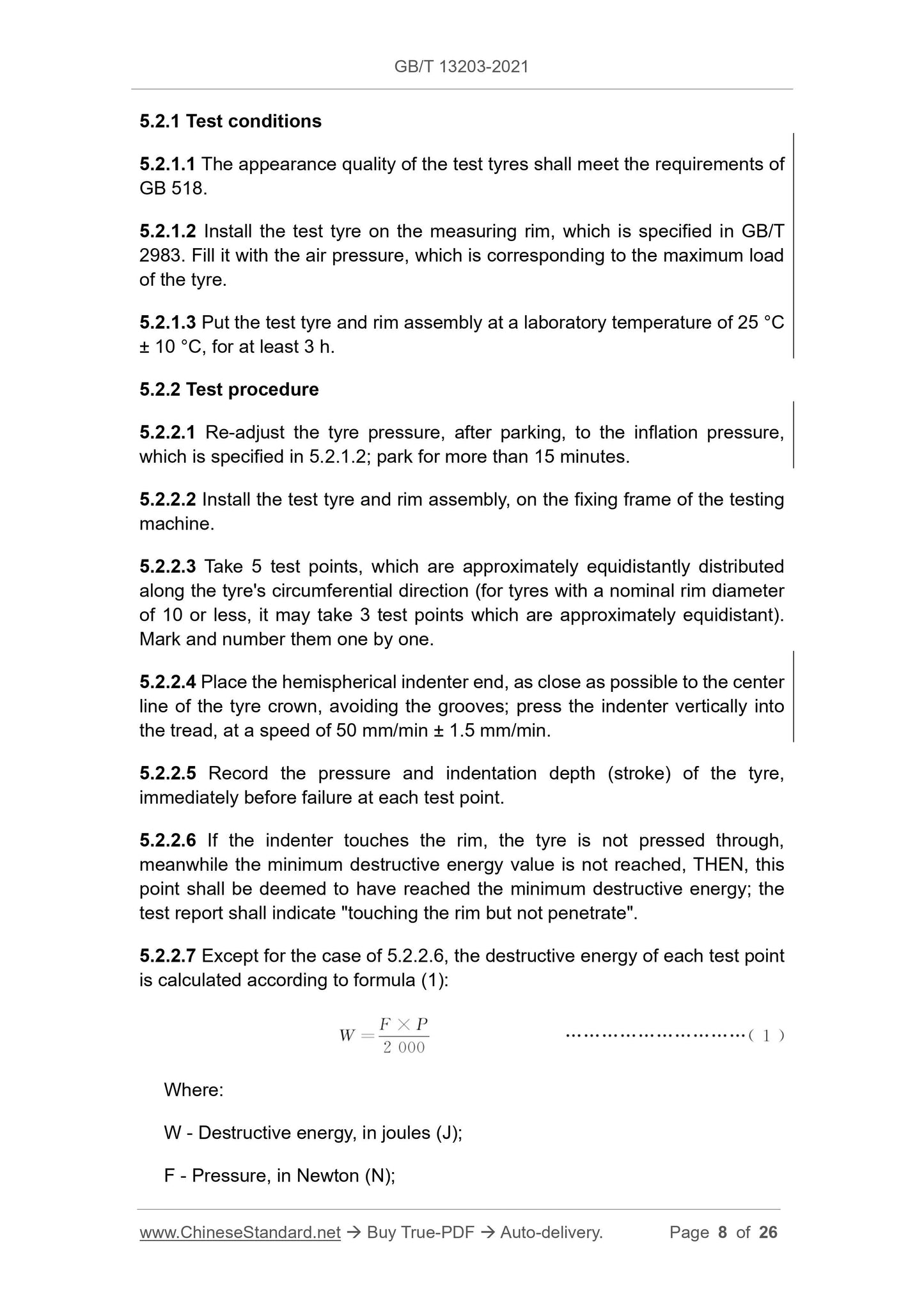
5.2.2.7 Except for the case of 5.2.2.6, the damage energy of each test point is calculated according to formula (1).
W =
F×P
(1)
Where.
W-destruction energy, in joules (J);
F---Pressure, the unit is Newton (N);
P---Pressing depth (stroke), the unit is millimeter (mm).
5.2.2.8 When using a device that can automatically calculate the damage energy, when the minimum damage energy specified in GB 518 is reached, the indenter can be stopped and continue to press.
Into the tire, and indicate "automatically stop pressure" in the test report. When using this device, the last point of all test points can be tested to tire failure
until. This should be noted in the test report at this time.
5.2.2.9 During the test, if the tubeless tire cannot maintain the inflation pressure, necessary measures can be taken (such as inserting a tube or adding a closure, etc.)
Carry out the test, but it should be noted in the test report.
5.3 Durability test
5.3.1 Test conditions
5.3.1.1 The appearance quality of the test tires should meet the requirements of GB 518.
5.3.1.2 Install the test tire on the measuring rim specified in GB/T 2983 and fill it with the air pressure corresponding to the maximum load capacity of the tire.
5.3.1.3 Park the test tire and rim assembly at a laboratory temperature of 38°C ± 3°C for at least 3 hours.
5.3.1.4 The tire pressure should not be adjusted throughout the test, and the test load should be kept stable at all stages.
5.3.1.5 During the whole test, the ambient temperature 150mm~1000mm away from the tire should not be lower than 35℃, and cooling tires should not be used.
installation.
5.3.2 Test procedure
5.3.2.1 Readjust the tire pressure after parking to the inflation pressure specified in 5.3.1.2.
5.3.2.2 Install the test tire and rim assembly prepared under the above conditions on the test shaft so that it is perpendicular to the outer surface of the test drum
And impose the test load, see Table 1.
Table 1 Durability test procedure
Test phase
Test load (the percentage of the tire corresponding to the maximum load capacity)
Test time
Get Quotation: Click GB/T 13203-2021 (Self-service in 1-minute)
Historical versions (Master-website): GB/T 13203-2021
Preview True-PDF (Reload/Scroll-down if blank)
GB/T 13203-2021: Test methods for verifying capabilities of motorcycle tyres
GB/T 13203-2021
Test methods for verifying capabilities of motorcycle tyres
ICS 83.160.10
CCSG41
National Standards of People's Republic of China
Replace GB/T 13203-2014
Motorcycle tire performance test method
(ISO 10231.2003, Motorcycletyres-Testmethodsforverifyingtyre
capabilities,MOD)
Released on 2021-08-20
2022-03-01 implementation
State Administration of Market Supervision and Administration
Issued by the National Standardization Management Committee
Motorcycle tire performance test method
1 Scope
This document specifies terms and definitions, test equipment and accuracy, test methods, judgment rules and test reports for motorcycle tire performance testing.
tell. This document includes the strength performance test method, durability test method, high-speed performance test method and centrifugal expansion test of motorcycle tires.
验方法。 Test methods.
This document applies to new pneumatic motorcycle tires.
The high-speed performance test method in this document is not applicable to motorcycle pneumatic tires with a maximum speed capability of less than 100km/h.
The centrifugal swelling test method in this document is only applicable to motorcycles with speed symbol P (the maximum speed capacity is 150km/h) and above
Car with pneumatic tires.
2 Normative references
The contents of the following documents constitute the indispensable clauses of this document through normative references in the text. Among them, dated quotations
Only the version corresponding to that date is applicable to this document; for undated reference documents, the latest version (including all amendments) is applicable to
This document.
GB 518 motorcycle tires
GB/T 2983 Motorcycle Tire Series
GB/T 6326 tire terms and their definitions (GB/T 6326-2014, ISO 4223-1.2002, NEQ)
3 Terms and definitions
The following terms and definitions defined in GB/T 6326 apply to this document.
3.1
Test drum speed testdrumspeed
The surface speed of the outer circumference of the steel test drum.
3.2
Tyrespeed
The speed of the outer surface of the tire tread.
3.3
Maximumloadrating
The maximum load rating of the tire at the highest speed.
Note. The maximum speed refers to the speed corresponding to the speed symbol on the tire or the maximum speed capability of the tire specified by the tire manufacturer.
4 Test equipment and accuracy
4.1 High-speed durability testing machine
4.1.1 The diameter of the drum of the testing machine is 1700mm±17mm.
4.1.2 The surface of the drum of the testing machine should be a smooth steel surface with a radial runout ≤ 0.25 mm, and the width should be greater than the total inflated section of the test tire.
width.
4.1.3 The loading capacity of the test loading device shall meet the requirements of the test, and its accuracy shall be ±1.5% of the full scale.
4.1.4 The speed capability of the drum of the testing machine shall meet the requirements of the test, and its accuracy shall be ±3% of the full scale.
4.2 Strength testing machine
4.2.1 A steel cylindrical indenter with sufficient length shall be provided on the testing machine, and the end of the indenter shall be a half diameter of 8.0mm±0.2mm.
spherical.
4.2.2 The loading capacity of the loading device of the testing machine should not exceed.2000kg.
4.2.3 The display accuracy of indenter displacement and pressure is ±1% of full scale. The control accuracy of the displacement speed of the indenter should be ±3% of the full scale.
4.3 Inflation pressure gauge
The maximum range of the inflation pressure gauge should not be less than 400kPa, with an accuracy of ±10kPa.
4.4 Centrifugal expansion test device
4.4.1 Test shaft
For the tire centrifugal expansion test, when measuring the vertical part of the inner flange of the rim directly above the bead seat and the round corner of the bead seat, the test
The inspection shaft and rim should be controlled to ensure that the radial deviation is less than ±0.5mm, and the lateral deviation is less than ±0.5mm.
4.4.2 Contour drawing device
For example, design coordinates, cameras, etc. can be used to obtain a clear contour line of the maximum point of deformation of the outer contour of the tire cross section. The device should be deformed
The change is reduced to a minimum, and it is ensured that the drawn outline has a constant (known) ratio to the actual size.
The device should use the axis of rotation as a reference for the tire profile.
The accuracy of the tire centrifugal expansion test measurement equipment should be ±1% of the full scale.
Note. For the test only to detect whether the centrifugal expansion size of motorcycle tires meets the relevant limits under dynamic conditions, the centrifugal expansion test can also be selected.
Limit detection methods (such as photoelectric control, contour plate control, etc., see 5.5.3). Can establish an enveloping curve, or a centrifugal radius control line---the tire is divided equally
The allowable maximum deformation point of the tread on the line is used as the basis for the limit device of the tire's centrifugal expansion size. The relevant profile curve is shown in Appendix C.
5 Test method
5.1 General
Use 3 or 4 tires with the same characteristics (such as specification mark, maximum load capacity and speed class) as test samples, respectively
It is used for strength performance test, durability test, high-speed performance test, and centrifugal swelling test if necessary.
Each test sample shall meet the test method requirements specified in 5.2~5.5 respectively.
5.2 Strength performance test
5.2.1 Test conditions
5.2.1.1 The appearance quality of the test tires should meet the requirements of GB 518.
5.2.1.2 Install the test tire on the measuring rim specified in GB/T 2983 and fill it with the air pressure corresponding to the maximum load of the tire.
5.2.1.3 Put the test tire and rim assembly at a laboratory temperature of 25℃±10℃ for at least 3h.
5.2.2 Test procedure
5.2.2.1 Re-adjust the tire pressure after parking to the inflation pressure specified in 5.2.1.2, and park for more than 15 minutes.
5.2.2.2 Install the test tire and rim assembly on the fixing frame of the testing machine.
5.2.2.3 Take 5 test points approximately equidistantly distributed along the tire circumferential direction (for tires with a nominal rim diameter of 10 or less, approximately
3 test points at equal distances), mark and number one by one.
5.2.2.4 Place the hemispherical indenter end as close to the centerline of the tire crown as possible, avoid the grooves, and press the indenter at a speed of 50mm/min±1.5mm/min.
The head is pressed vertically into the tread.
5.2.2.5 Record the pressure and indentation depth (stroke) of the tire immediately before failure at each test point.
5.2.2.6 If the indenter touches the rim, the tire is not pressed through, and the minimum damage energy value is not reached, then this point shall be deemed to have reached the minimum damage energy, and
The test report indicated "touching the rim but not wearing it".
5.2.2.7 Except for the case of 5.2.2.6, the damage energy of each test point is calculated according to formula (1).
W =
F×P
(1)
Where.
W-destruction energy, in joules (J);
F---Pressure, the unit is Newton (N);
P---Pressing depth (stroke), the unit is millimeter (mm).
5.2.2.8 When using a device that can automatically calculate the damage energy, when the minimum damage energy specified in GB 518 is reached, the indenter can be stopped and continue to press.
Into the tire, and indicate "automatically stop pressure" in the test report. When using this device, the last point of all test points can be tested to tire failure
until. This should be noted in the test report at this time.
5.2.2.9 During the test, if the tubeless tire cannot maintain the inflation pressure, necessary measures can be taken (such as inserting a tube or adding a closure, etc.)
Carry out the test, but it should be noted in the test report.
5.3 Durability test
5.3.1 Test conditions
5.3.1.1 The appearance quality of the test tires should meet the requirements of GB 518.
5.3.1.2 Install the test tire on the measuring rim specified in GB/T 2983 and fill it with the air pressure corresponding to the maximum load capacity of the tire.
5.3.1.3 Park the test tire and rim assembly at a laboratory temperature of 38°C ± 3°C for at least 3 hours.
5.3.1.4 The tire pressure should not be adjusted throughout the test, and the test load should be kept stable at all stages.
5.3.1.5 During the whole test, the ambient temperature 150mm~1000mm away from the tire should not be lower than 35℃, and cooling tires should not be used.
installation.
5.3.2 Test procedure
5.3.2.1 Readjust the tire pressure after parking to the inflation pressure specified in 5.3.1.2.
5.3.2.2 Install the test tire and rim assembly prepared under the above conditions on the test shaft so that it is perpendicular to the outer surface of the test drum
And impose the test load, see Table 1.
Table 1 Durability test procedure
Test phase
Test load (the percentage of the tire corresponding to the maximum load capacity)
Test time
Share