1
/
of
10
PayPal, credit cards. Download editable-PDF & invoice in 1 second!
GB/T 13298-2015 English PDF (GBT13298-2015)
GB/T 13298-2015 English PDF (GBT13298-2015)
Regular price
$125.00 USD
Regular price
Sale price
$125.00 USD
Unit price
/
per
Shipping calculated at checkout.
Couldn't load pickup availability
Delivery: 3 seconds. Download true-PDF + Invoice.
Get QUOTATION in 1-minute: Click GB/T 13298-2015
Historical versions: GB/T 13298-2015
Preview True-PDF (Reload/Scroll if blank)
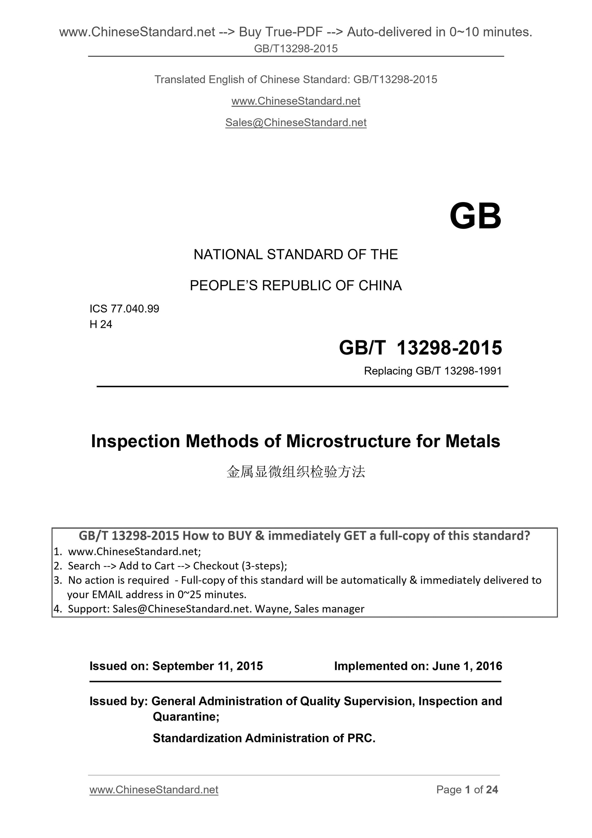
GB/T 13298-2015: Inspection methods of microstructure for metals
GB/T 13298-2015
GB
NATIONAL STANDARD OF THE
PEOPLE’S REPUBLIC OF CHINA
ICS 77.040.99
H 24
Replacing GB/T 13298-1991
Inspection Methods of Microstructure for Metals
ISSUED ON. SEPTEMBER 11, 2015
IMPLEMENTED ON. JUNE 1, 2016
Issued by. General Administration of Quality Supervision, Inspection and
Quarantine;
Standardization Administration of PRC.
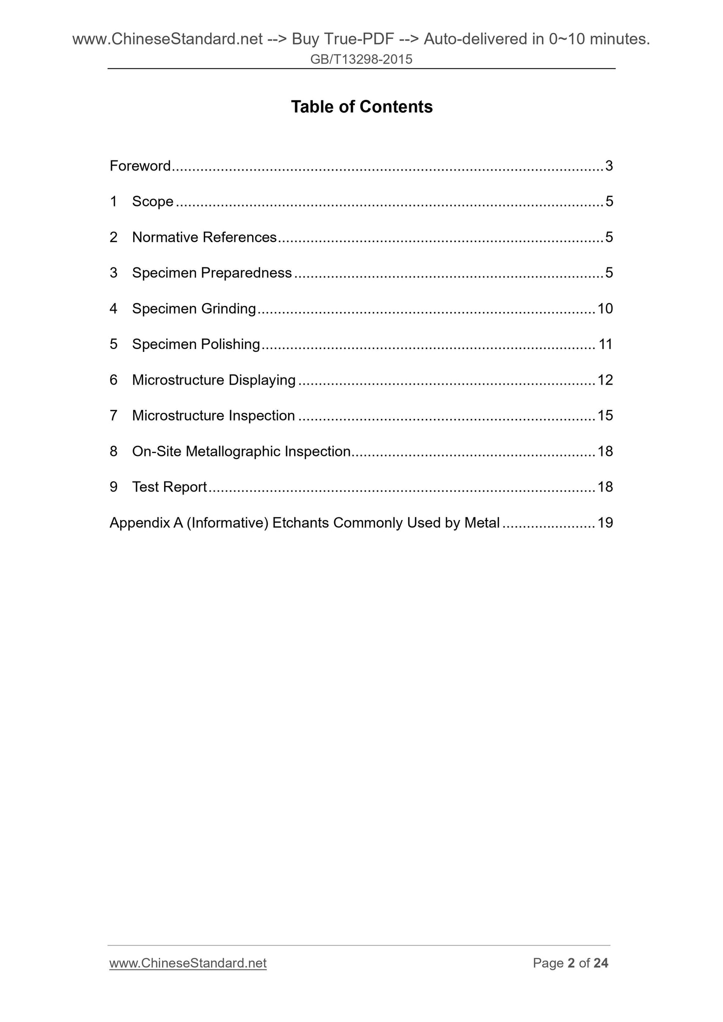
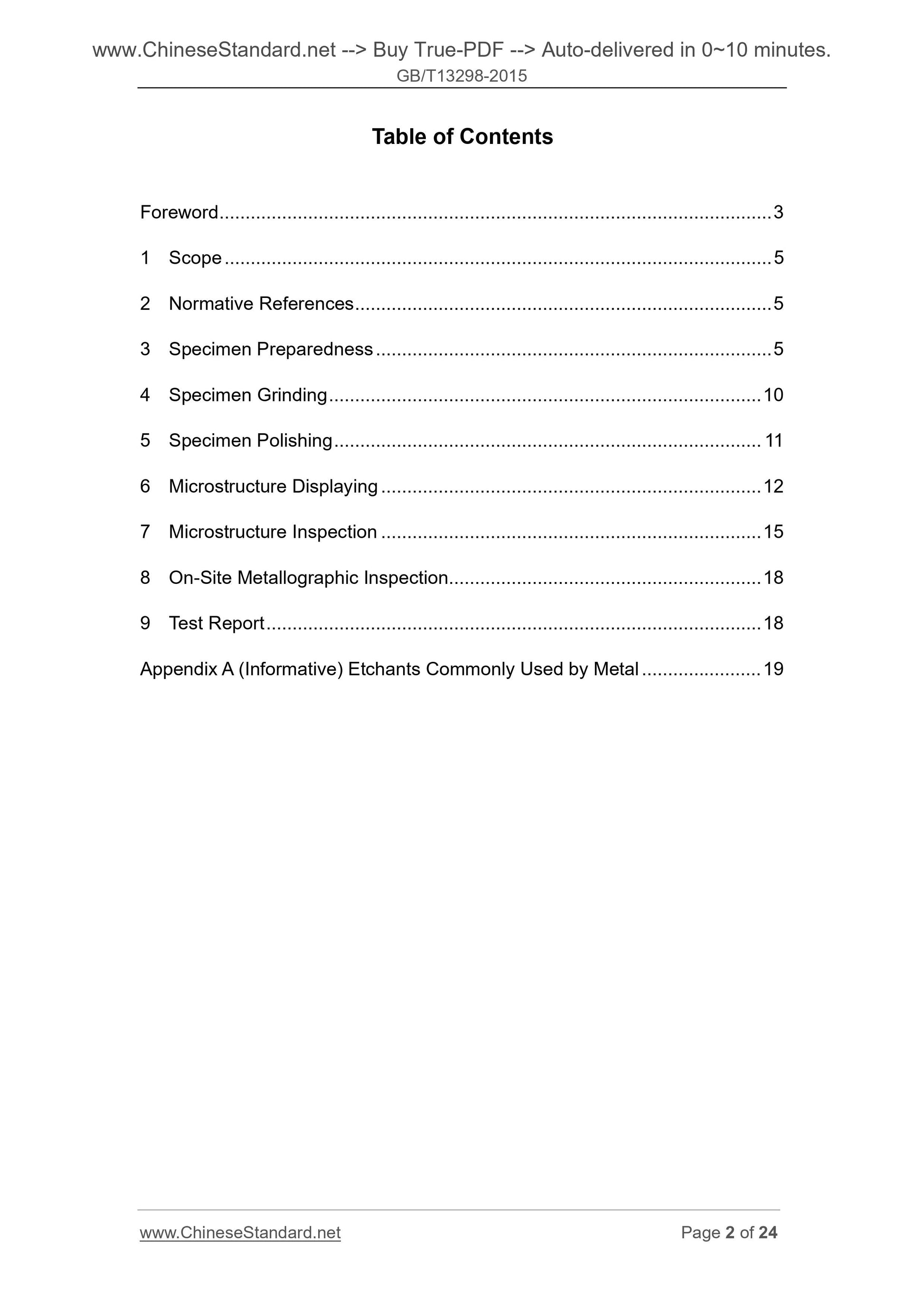
Table of Contents
Foreword ... 3
1 Scope ... 5
2 Normative References ... 5
3 Specimen Preparedness ... 5
4 Specimen Grinding ... 10
5 Specimen Polishing ... 11
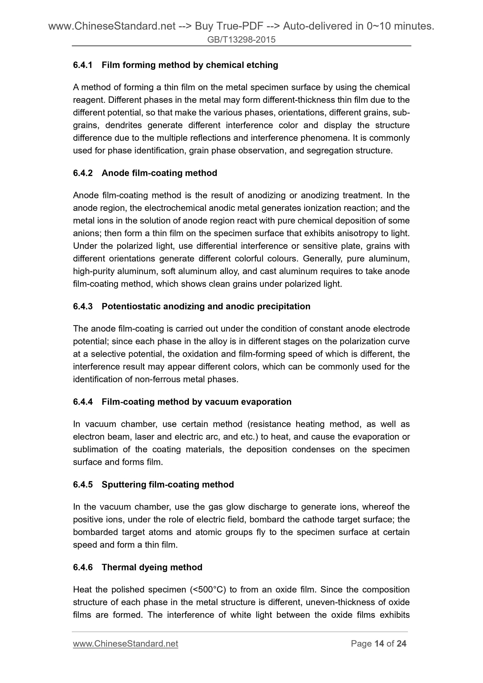
6 Microstructure Displaying ... 12
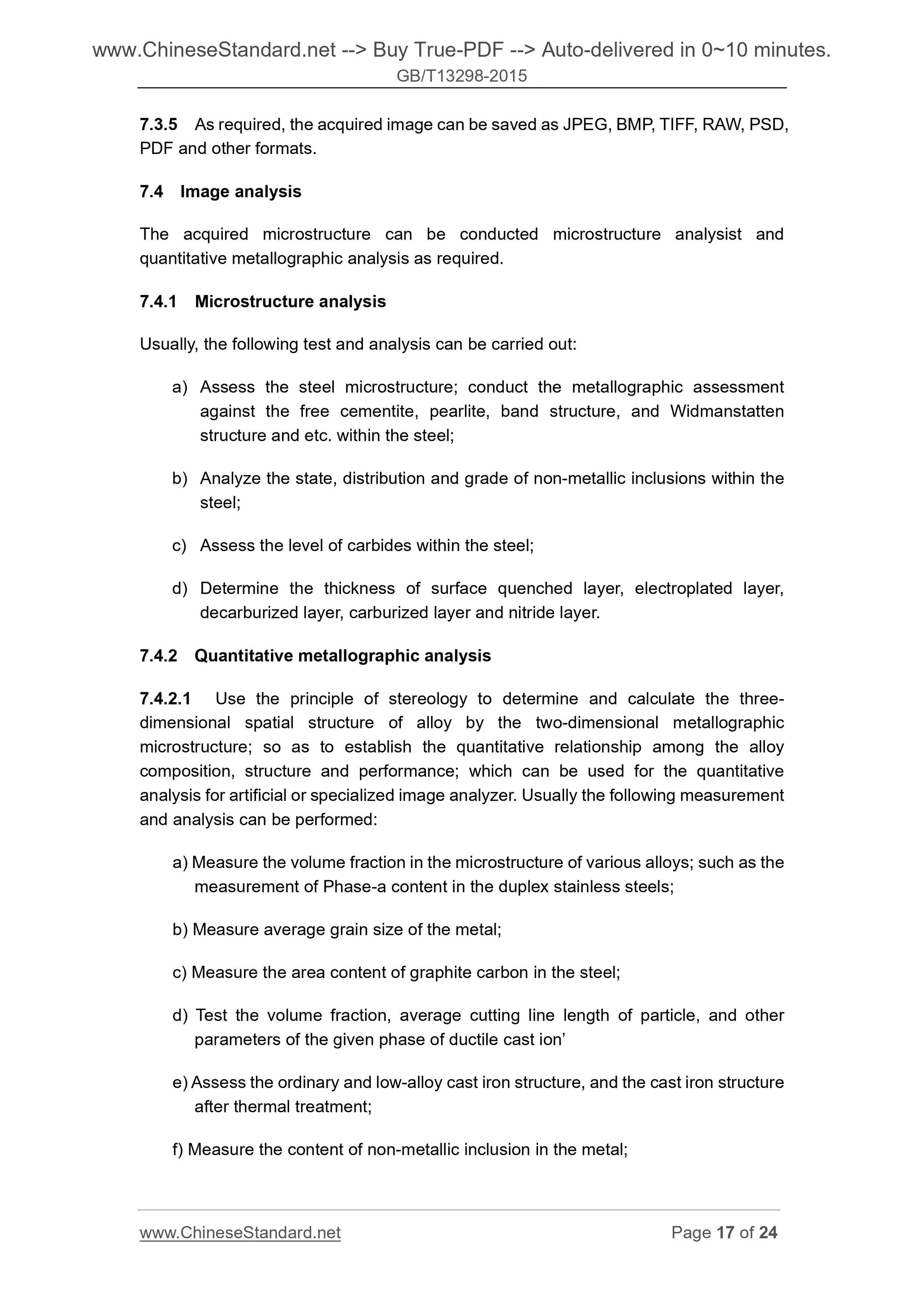
7 Microstructure Inspection ... 15
8 On-Site Metallographic Inspection... 18
9 Test Report ... 18
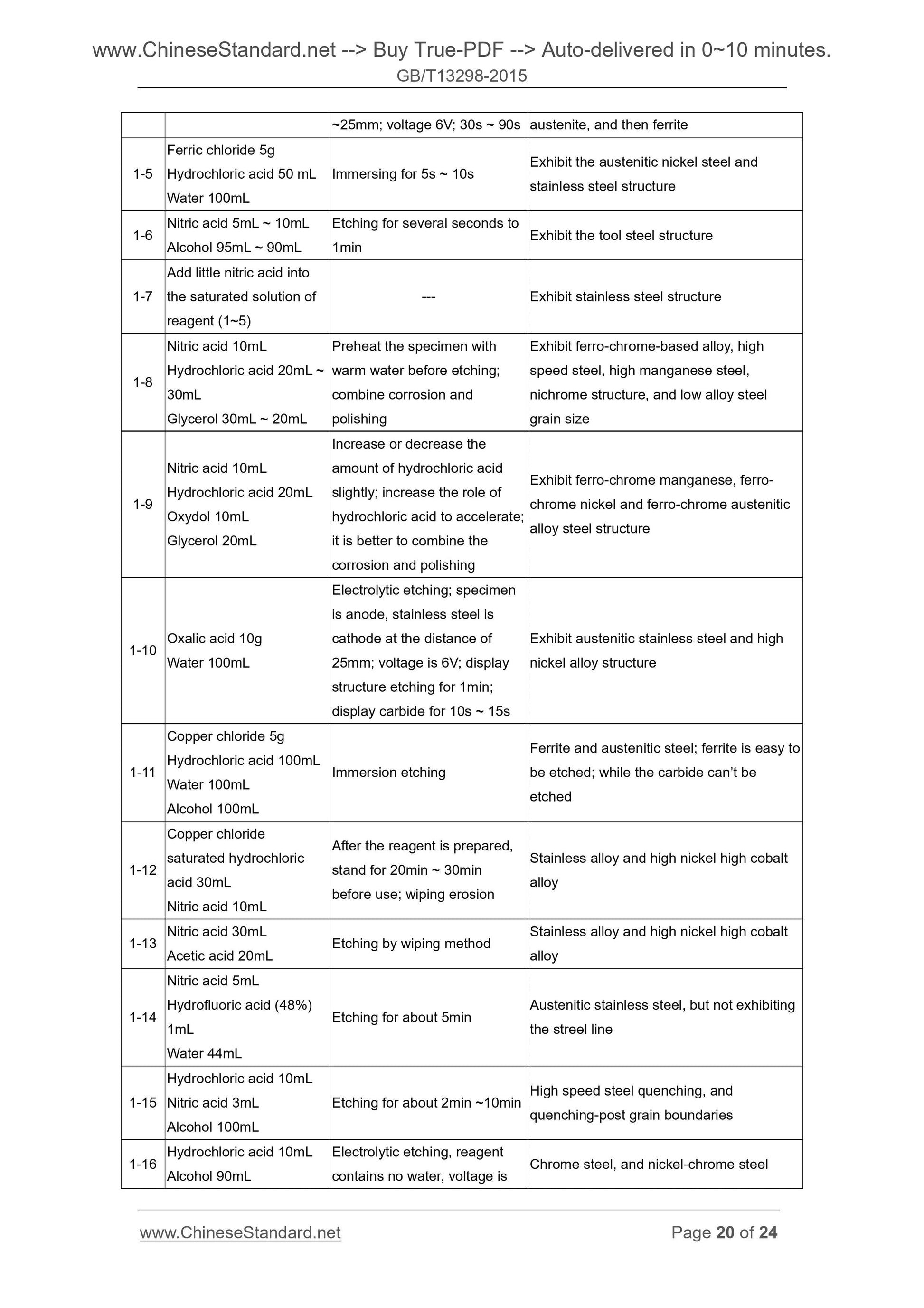
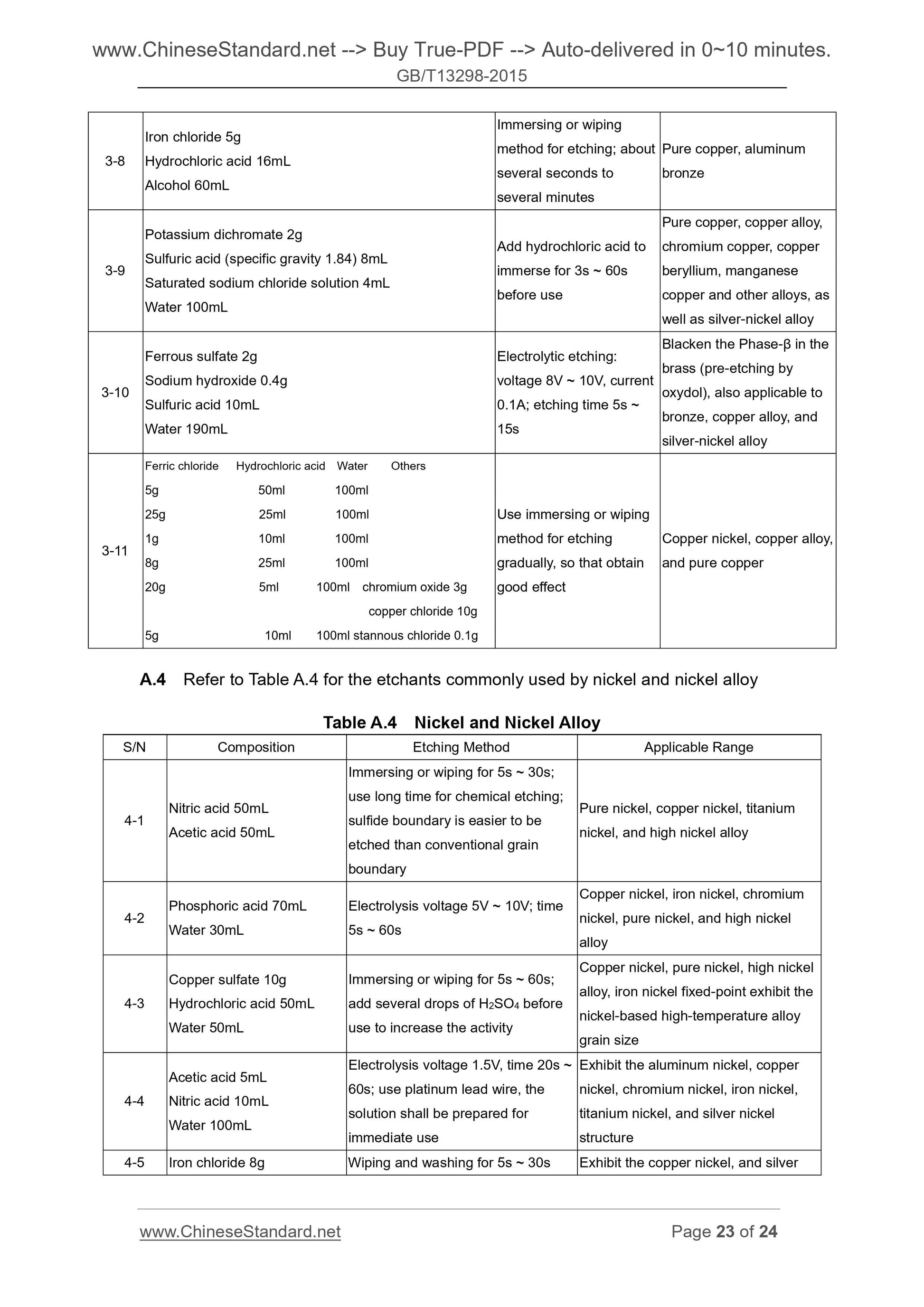
Appendix A (Informative) Etchants Commonly Used by Metal ... 19
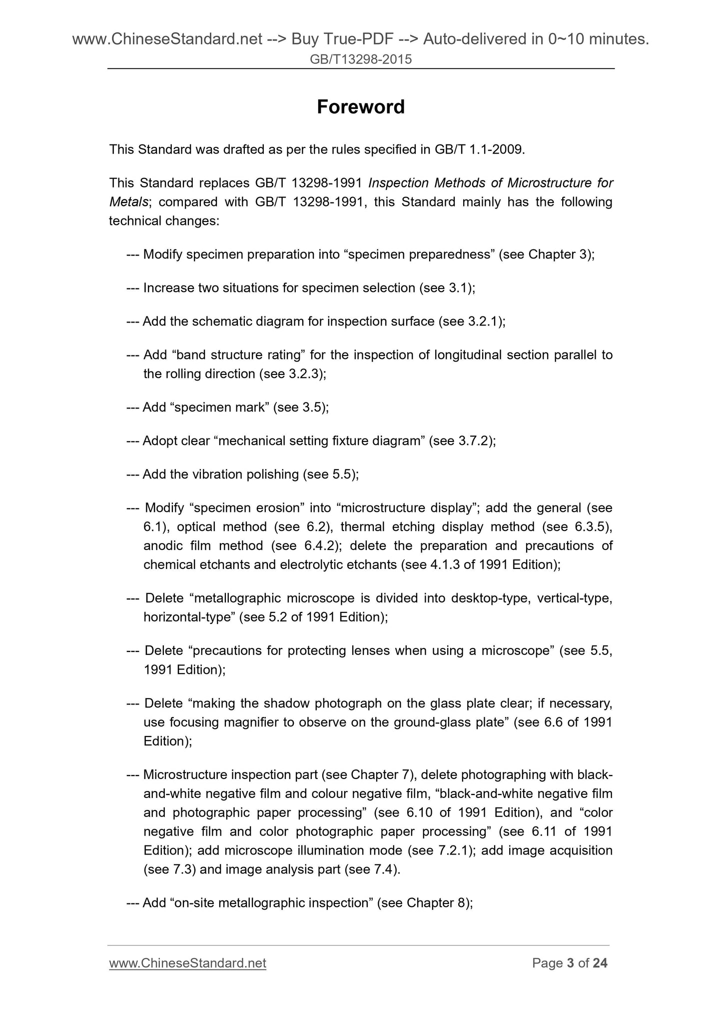
Foreword
This Standard was drafted as per the rules specified in GB/T 1.1-2009.
This Standard replaces GB/T 13298-1991 Inspection Methods of Microstructure for
Metals; compared with GB/T 13298-1991, this Standard mainly has the following
technical changes.
--- Modify specimen preparation into “specimen preparedness” (see Chapter 3);
--- Increase two situations for specimen selection (see 3.1);
--- Add the schematic diagram for inspection surface (see 3.2.1);
--- Add “band structure rating” for the inspection of longitudinal section parallel to
the rolling direction (see 3.2.3);
--- Add “specimen mark” (see 3.5);
--- Adopt clear “mechanical setting fixture diagram” (see 3.7.2);
--- Add the vibration polishing (see 5.5);
--- Modify “specimen erosion” into “microstructure display”; add the general (see
6.1), optical method (see 6.2), thermal etching display method (see 6.3.5),
anodic film method (see 6.4.2); delete the preparation and precautions of
chemical etchants and electrolytic etchants (see 4.1.3 of 1991 Edition);
--- Delete “metallographic microscope is divided into desktop-type, vertical-type,
horizontal-type” (see 5.2 of 1991 Edition);
--- Delete “precautions for protecting lenses when using a microscope” (see 5.5,
1991 Edition);
--- Delete “making the shadow photograph on the glass plate clear; if necessary,
use focusing magnifier to observe on the ground-glass plate” (see 6.6 of 1991
Edition);
--- Microstructure inspection part (see Chapter 7), delete photographing with black-
and-white negative film and colour negative film, “black-and-white negative film
and photographic paper processing” (see 6.10 of 1991 Edition), and “color
negative film and color photographic paper processing” (see 6.11 of 1991
Edition); add microscope illumination mode (see 7.2.1); add image acquisition
(see 7.3) and image analysis part (see 7.4).
--- Add “on-site metallographic inspection” (see Chapter 8);
Inspection Methods of Microstructure for Metals
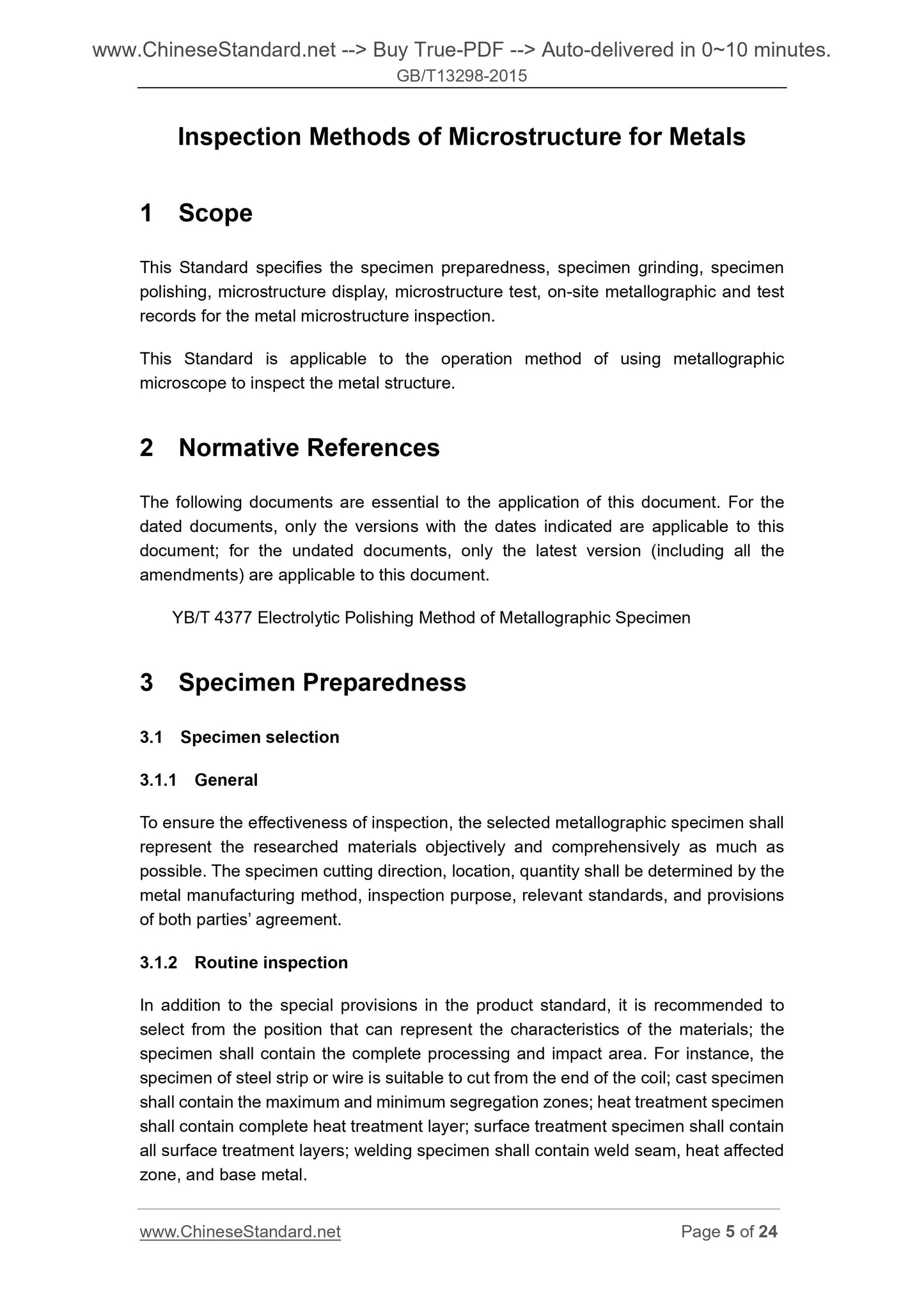
1 Scope
This Standard specifies the specimen preparedness, specimen grinding, specimen
polishing, microstructure display, microstructure test, on-site metallographic and test
records for the metal microstructure inspection.
This Standard is applicable to the operation method of using metallographic
microscope to inspect the metal structure.
2 Normative References
The following documents are essential to the application of this document. For the
dated documents, only the versions with the dates indicated are applicable to this
document; for the undated documents, only the latest version (including all the
amendments) are applicable to this document.
YB/T 4377 Electrolytic Polishing Method of Metallographic Specimen
3 Specimen Preparedness
3.1 Specimen selection
3.1.1 General
To ensure the effectiveness of inspection, the selected metallographic specimen shall
represent the researched materials objectively and comprehensively as much as
possible. The specimen cutting direction, location, quantity shall be determined by the
metal manufacturing method, inspection purpose, relevant standards, and provisions
of both parties’ agreement.
3.1.2 Routine inspection
In addition to the special provisions in the product standard, it is recommended to
select from the position that can represent the characteristics of the materials; the
specimen shall contain the complete processing and impact area. For instance, the
specimen of steel strip or wire is suitable to cut from the end of the coil; cast specimen
shall contain the maximum and minimum segregation zones; heat treatment specimen
shall contain complete heat treatment layer; surface treatment specimen shall contain
all surface treatment layers; welding specimen shall contain weld seam, heat affected
zone, and base metal.
during the cutting period, so that prevent the structure changes.
3.5 Specimen mark
In order to avoid confusion during the specimen preparedness period, the specimen
registration and marking shall be done well. Once the specimen is cut, print and
engrave mark beyond the inspection surface of the specimen; ensure the mark shall
not be worn, shielded during the specimen cleaning and heat treatment processes. If
the specimen requires follow-up embedding, then make marks again after embedding.
3.6 Specimen cleaning
If the specimen surface is stained with grease, dirt, or residue, proper solvent (such as
alcohol, acetone, and etc.) can be used to clean; cleaning can be conducted in the
ultrasonic wave. Any metal coating that hinders the corrosion of the base metal shall
be removed prior to grinding.
3.7 Specimen embedding
3.7.1 General
The following conditions of specimens need embedding such as small size specimen
(such as sheet, ribbon material, thin tube, and etc.), too soft and brittle specimen,
irregular specimen, inspecting the specimen edge structure, using automatic grinding
and polishing machine for the specimen preparation. The applied embedding method
shall not change the original structure; the inspection surface of the specimen shall be
downward during the embedding period. According to the actual needs, the
mechanical embedding (see 3.7.2) or resin embedding (see 3.7.3) methods shall be
selected.
3.7.2 Mechanical embedding method
3.7.2.1 Fasten the specimen in a suitable fixture with bolts and screws (see Figure
2). The fixture hardness shall be close to the specimen hardness; so as to reduce the
rounding role against the edges when grinding and polishing the specimen; the fixture
composition shall be similar to the specimen to avoid forming the galvanic interaction
influencing the corrosion effect.
NOTE. pay attention that the specimen shall closely contact with the fixture; be careful when
fixing the specimen; if the clamping force is too large, it may damage the soft material specimen.
3.7.2.2 To reduce the penetration of polishing agent and etchant, the sheet made of
soft materials can be used to fill the gaps of specimen; which shall ensure no
electrolytic reaction shall occur between filling materials and specimen during the
corrosion period. The typical filling materials include thin plastic sheet, lead or copper.
In order to reduce the absorption of gaps against the polishing agent and etchant, the
epoxide resin layer can paint to the specimen before holding; or immerse the specimen
5 Specimen Polishing
5.1 General
Polish the grinding mark on the specimen to reach the mirror finish, and there are no
grinding defects. The polishing method can take mechanical polishing, electrolytic
polishing, chemical polishing, vibration polishing, micro-grinding and so on.
5.2 Mechanical polishing
5.2.1 Rough polishing
After the burnis...
Share
