1
/
of
9
PayPal, credit cards. Download editable-PDF and invoice in 1 second!
GB/T 14048.4-2020 English PDF (GBT14048.4-2020)
GB/T 14048.4-2020 English PDF (GBT14048.4-2020)
Regular price
$1,805.00 USD
Regular price
Sale price
$1,805.00 USD
Unit price
/
per
Shipping calculated at checkout.
Couldn't load pickup availability
Delivery: 3 seconds. Download true-PDF + Invoice.
Get Quotation: Click GB/T 14048.4-2020 (Self-service in 1-minute)
Historical versions (Master-website): GB/T 14048.4-2020
Preview True-PDF (Reload/Scroll-down if blank)
GB/T 14048.4-2020: Low-voltage switchgear and controlgear -- Part 4-1: Contactors and motor-starters -- Electromechanical contactors and motor-starters(Including motor protector)
GB/T 14048.4-2020
Low-voltage switchgear and controlgear -- Part 4-1.Contactors and motor-starters -- Electromechanical contactors and motor-starters(Including motor protector)
ICS 29.130.20
K32
National Standards of People's Republic of China
Replacing GB/T 14048.4-2010
Low-voltage switchgear and controlgear
Part 4-1.Contactors and Motor Starters
Electromechanical contactors and motor starters
(including motor protector)
motor-starters, MOD)
2020-09-29 Released 2021-04-01 Implementation
State Administration for Market Regulation
Released by the National Standardization Administration
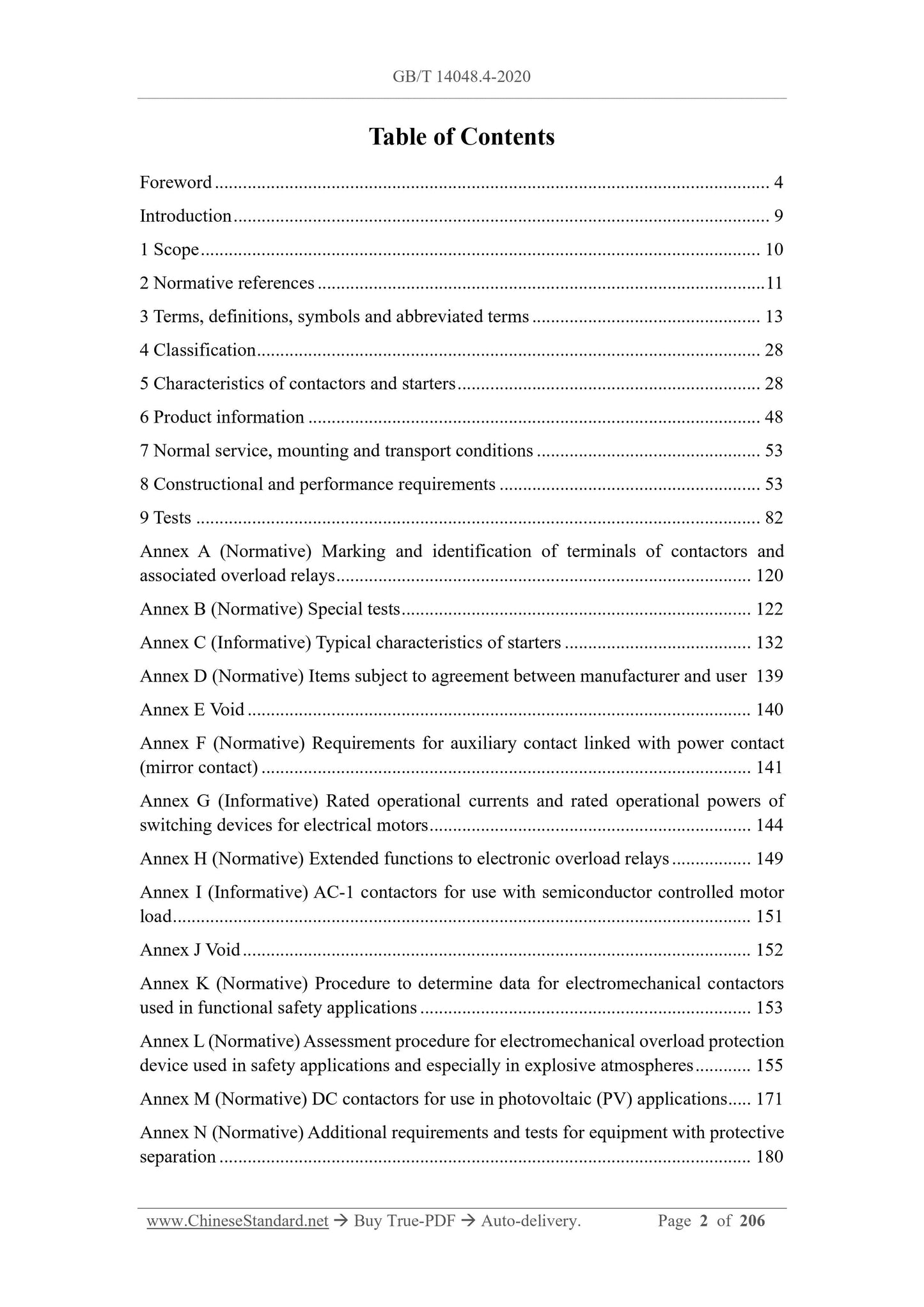
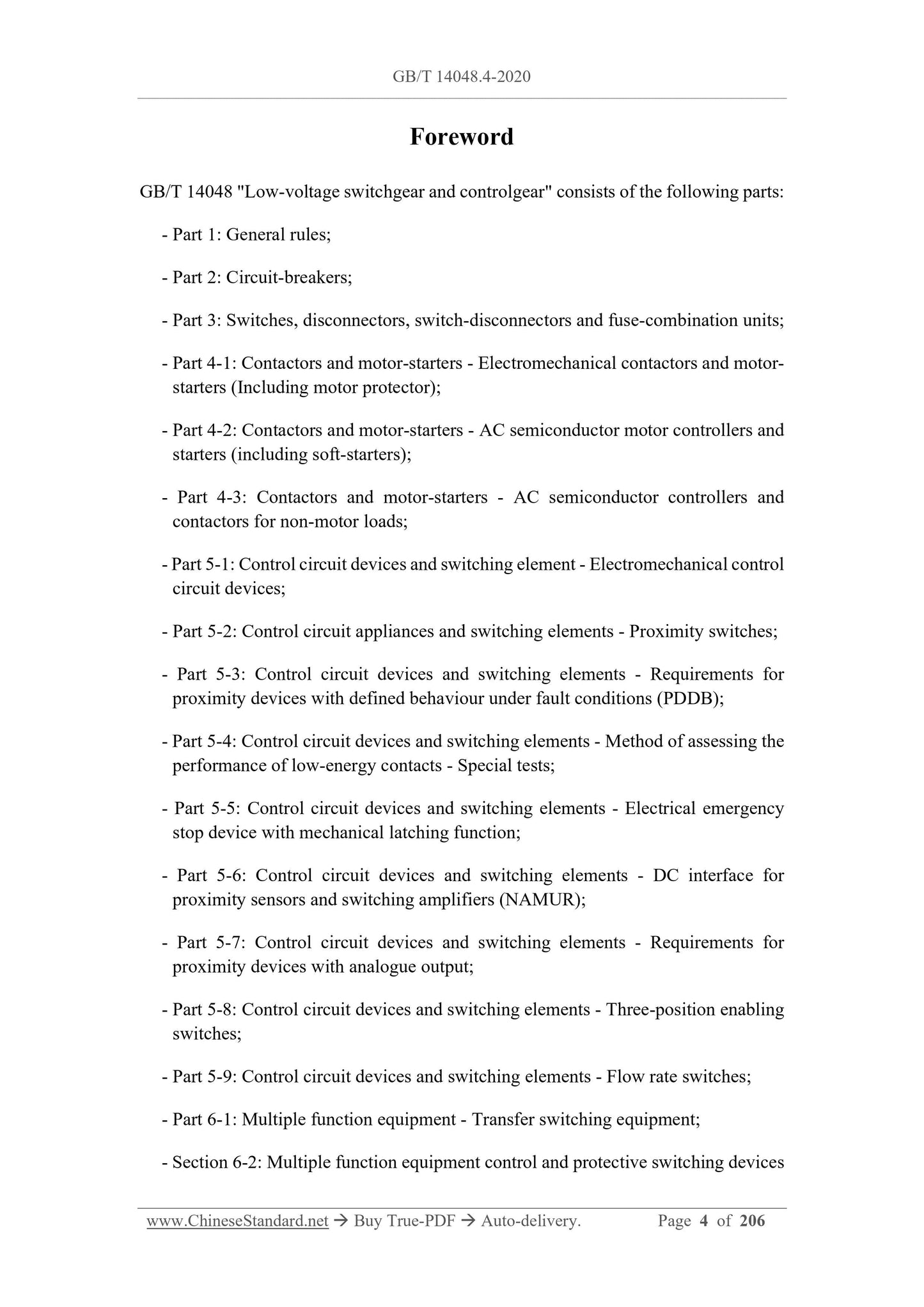
directory
Preface I
Introduction IV
1 Scope 1
2 Normative references 1
3 Terms and Definitions, Symbols and Abbreviations 3
4 Category 11
5 Characteristics of contactors and starters 11
6 Product Information 23
7 Normal conditions of use, installation and transport 26
8 Structural and performance requirements 26
9 Trials 46
Appendix A (Normative Appendix) Marking and Identification of Contactors and Corresponding Overload Relay Terminals 69
Appendix B (Normative Appendix) Special Test 71
Appendix C (Informative Appendix) Typical Characteristics of Starters 78
Appendix D (Normative Appendix) Submission of Clause 84 of the Manufacturer-User Agreement
Appendix E Empty 85
Appendix F (normative) Requirements for auxiliary contacts connected to power contacts (mirror contacts) 86
Appendix G (Informative Appendix) Rated Working Current and Rated Working Power of Switchgear for Motors 89
Appendix H (Normative Appendix) Extended Functions of Electronic Overload Relays 94
Appendix I (Informative Appendix) AC-1 Contactors for Semiconductor Controlled Motor Loads 96
Appendix J Empty 97
Appendix K (Normative) Steps for Determining Data on Electromechanical Contactors Used in Functional Safety Applications 98
Appendix L (Normative Appendix) Evaluation Procedures for Electromechanical Overload Protection Appliances for Safety Occasions (Especially in Explosive Atmospheres) 100
Appendix M (Normative) DC Contactors in Photovoltaic (PV) Applications 115
Annex N (normative) Additional requirements and tests for equipment with protective isolation 122
Appendix O (Informative) Load Monitoring 125
Appendix P (normative) Short-circuit breaking test of MPSD 129
Appendix Q (Normative Appendix) Coordination between MPSD and another short-circuit protective device in the same circuit under short-circuit conditions 133
Reference 139
Low-voltage switchgear and controlgear
Part 4-1.Contactors and Motor Starters
Electromechanical contactors and motor starters
(including motor protector)
1 Scope
This part of GB/T 14048 specifies.
a) Characteristics of the appliance.
b) the following conditions apply.
1) Operation and performance;
2) Dielectric properties;
3) Protection level;
4) Structure, including safety measures against electric shock, fire and mechanical hazards.
c) The tests used to confirm that the appliance meets these conditions, and the test methods.
d) Information to be given on the product or in the manufacturer's documentation.
This part also specifies procedures for evaluating electromechanical overload protection for safe locations, such as the protection of motors located in explosive atmospheres from external
environmental impacts (see Appendix L).
This section applies to.
--- Electromechanical contactors and starters, including motor protective switching devices (MPSD);
--- actuators for contactor relays;
--- Special contacts for contactors or contactor-type relay coil circuits;
--- Special accessories (such as special wiring, special lock accessories).
The above electrical appliances are connected to the power distribution circuit, motor circuit and other load circuits, and the rated voltage of AC does not exceed 1000V1) or DC does not exceed 1000V.
over 1500V.
1) Electrical appliances with AC rated voltage of 1140V can refer to this part. The performance and other requirements of the electrical appliance shall be determined through consultation between the manufacturer and the user.
This section does not apply to the following electrical appliances.
--- DC motor starter;
Note 1.Requirements for DC motor starters are considered in the next revision cycle.
---Auxiliary contacts of contactors and contacts of contactor relays, see GB/T 14048.5-2017 for relevant requirements;
--- Frequency control starter;
Note 2.Additional requirements for variable frequency speed starters are considered in the next revision cycle.
--- The built-in short-circuit protection device of the starter (except MPSD), see GB/T 14048.2-2020 and GB/T 14048.3 for relevant requirements;
--- For the use of products in explosive environments, see GB/T 3836 series for relevant requirements;
--- Embedded software design rules;
--- For network security, see IEC 62443 for relevant requirements.
2 Normative references
The following documents are essential for the application of this document. For dated references, only the dated version applies to this article
switch), and the on-off capacity, duty and starting characteristics are related to it.
The rated working voltage of the rotor is equal to when the rated working voltage is applied to the stator terminal of the motor, the motor is stopped and the rotor is open, and the measurement is performed between the slip rings.
obtained voltage.
The rated insulation voltage of the switchgear connected to the rotor circuit shall be at least 50% of the maximum voltage between the open slip rings.
NOTE. The electrical stress in the rotor is lower and of shorter duration than in the stator.
The rated rotor working voltage is only applied for a short time at the starting position, so the rated rotor working voltage is allowed to exceed the rated rotor insulation voltage.
Press 100%.
When selecting and configuring equipment, consideration should be given to the different live parts in the starter rotor circuit (eg switching devices, varistors, connectors
etc.) are not the same as the maximum voltages.
5.3.1.2 Rated insulation voltage (Ui)
5.3.1.2.1 General requirements
4.3.1.2 of GB/T 14048.1-2012 applies.
5.3.1.2.2 Rated stator insulation voltage (Uis)
The rated stator insulation voltage of the rotor varistor starter refers to the voltage value of the electrical appliances and their constituent units connected to the stator circuit, and is the same as the
Dielectric properties are related to creepage distances.
Unless otherwise specified, the rated stator insulation voltage is the maximum rated stator operating voltage of the starter.
5.3.1.2.3 Rated rotor insulation voltage (Uir)
The rated rotor insulation voltage of the rotor varistor starter refers to the electrical appliances and their constituent units (connecting wires, resistors) connected to the rotor circuit.
device, enclosure), and is related to the dielectric performance test and creepage distance.
5.3.1.3 Rated impulse withstand voltage (Uimp)
4.3.1.3 of GB/T 14048.1-2012 applies.
5.3.1.4 Rated starting voltage of auto decompression starter
The rated starting voltage of the auto-decompression starter is the reduced voltage obtained from the tap of the auto-transformer.
Preferred values for the rated starting voltage are 50%, 65% or 80% of the rated operating voltage.
5.3.2 Current or power
5.3.2.1 Conventional free air heating current (Ith)
4.3.2.1 of GB/T 14048.1-2012 applies.
5.3.2.2 Conventional enclosed thermal current (Ithe)
4.3.2.2 of GB/T 14048.1-2012 applies.
5.3.2.3 Conventional stator heating current (Iths)
The starter agrees that the stator heating current can be the heating current Iths under free air conditions (see 5.3.2.1), or the heating current under closed conditions.
Thermal current Ithes (see 5.3.2.2).
The stator heating current of the rotor varistor starter refers to the maximum current that the starter can carry under the working system of 8h (see 5.3.4.1).
When the starter is tested according to 9.3.3.3 under this current, the temperature rise of each part shall not exceed the limit value specified in 8.2.2.
5.3.2.4 Conventional rotor heating current (Ithr)
The starter agrees that the rotor heating current can be the heating current Ithr under free air conditions (see 5.3.2.1), or the heating current under closed conditions.
Thermal current Ither (see 5.3.2.2).
The rotor heating current of the rotor varistor starter refers to the rotor current in the starter at the running position (that is, after the resistor is removed).
The maximum current that each part can carry under the 8h working system (see 5.3.4.1), the starter is tested according to 9.3.3.3 under this current, and its temperature
The liter shall not exceed the limit specified in 8.2.2.
Note 1.For those components (switching appliances, connecting wires, resistors) that virtually no current flows in the closed position, confirm that the rated operation specified by the manufacturer
Under the system (see 5.3.4), the integral value ∫
i2dt will not cause a temperature rise above the limit specified in 8.2.2.
Note 2.When the starter is built with a resistor, consider its influence on the temperature rise.
5.3.2.5 Rated working current (Ie) or rated working power
The rated working current of the contactor or starter is based on the rated working voltage (see 5.3.1.1), the conventional free air heating current or
Agreed closed thermal current, rated current of overload relay, rated frequency (see 5.3.3), rated duty (see 5.3.4), use category (see 5.3.4)
5.4) and the case of the enclosure protection type (if any), the manufacturer shall make corresponding provisions.
For electrical appliances that directly switch on and off a single motor, the rated working current may be the maximum value of the connected motor under the condition of rated working voltage.
Instead of or in addition to the rated output power, the manufacturer shall provide the relationship between motor power and current.
Note. Appendix G gives the relevant values of the relationship between the rated working current and the rated working power.
For starters, the rated operating current (Ie) refers to the current of the starter in the operating position.
5.3.2.6 Rated stator working current (Ies) or rated stator working power
The rated stator working current of the rotor varistor starter is based on the rated current and rated current of the overload relay installed in the starter.
Sub-working voltage (see 5.3.1.1.1), conventional free air heating current or conventional enclosed heating current, rated frequency (see 5.3.3), rated work
In the case of system (see 5.3.4), starting characteristics (see 5.3.5.6) and enclosure protection type, the manufacturer shall make corresponding provisions.
The rated stator working current is the maximum rated output power of the motor controlled by the starter stator element under the rated stator working voltage.
rate instead. The manufacturer shall provide the relationship between motor power and stator current.
5.3.2.7 Rated rotor working current (Ier)
The rated rotor working current of the rotor varistor starter is based on the rated rotor working voltage (see 5.3.1.1.2), the agreed free air
Gas heating current or rotor enclosed heating current, rated frequency (see 5.3.3), rated duty (see 5.3.4), starting characteristics (see 5.3.5.6) and
In the case of the type of enclosure protection, the manufacturer shall make corresponding provisions.
The rated rotor operating current is equal to the amount of current flowing through the rotor when the rotor is short-circuited, the motor is running at full load, and the stator is supplied with rated voltage and rated frequency.
conductor current.
When the rated value of the rotor part of the rotor varistor starter is specified separately, in addition to specifying the rated working current of the rotor, a supplementary specification can also be used.
Under the condition of fixed and rated rotor working voltage, the maximum value of the motor controlled by the components of the starter (switching electrical appliances, connecting wires, relays, resistors)
rated output power. This power varies mainly with the predetermined fatigue torque, so its starting characteristics should be considered (see 5.3.5.6).
5.3.2.8 Rated uninterruptible current (Iu)
4.3.2.4 of GB/T 14048.1-2012 applies.
5.3.3 Rated frequency
4.3.3 of GB/T 14048.1-2012 applies.
5.3.4 Rated duty
5.3.4.1 8h working system (continuous working system)
4.3.4.1 of GB/T 14048.1-2012 applies, and the following requirements are added.
For star-delta starters, two-stage auto-decompression starters or rotor varistor starters, it means that the main contact of the starter is in the running position.
When kept closed, each main contact carries a steady current for long enough to bring the starter into thermal equilibrium, but not energized for more than
8h working system.
5.3.4.2 Uninterrupted work
4.3.4.2 of GB/T 14048.1-2012 applies, and the following requirements are added.
For star-delta starters, two-stage auto-decompression starters or rotor varistor starters, it means that the main contact of the starter is in the running position.
Keep closed, carry a stable current and last for more than 8h (weeks, months, years) without breaking the working system.
5.3.4.3 Intermittent cycle or intermittent duty
4.3.4.3 of GB/T 14048.1-2012 applies, and the following requirements are added.
For the decompression starter, it means that the main contact of the switchgear of the starter is kept closed at the running position and the no-load time is kept constant.
The ratio of, and both are short enough to make the starter reach thermal equilibrium.
The preferred levels of intermittent duty are.
---Contactor. The number of operating cycles per hour (operating frequency) is. 1, 3, 12, 30, 120, 300, 1200;
---Starter. The number of operating cycles per hour (operating frequency) is. 1, 3, 12, 30.
The operating cycle refers to a complete working cycle of one closing operation and one opening operation.
For starters, an operating cycle includes starting, running to rated speed and disconnecting the power to the motor.
Note. For starters under intermittent duty, the difference in thermal time cons...
Get Quotation: Click GB/T 14048.4-2020 (Self-service in 1-minute)
Historical versions (Master-website): GB/T 14048.4-2020
Preview True-PDF (Reload/Scroll-down if blank)
GB/T 14048.4-2020: Low-voltage switchgear and controlgear -- Part 4-1: Contactors and motor-starters -- Electromechanical contactors and motor-starters(Including motor protector)
GB/T 14048.4-2020
Low-voltage switchgear and controlgear -- Part 4-1.Contactors and motor-starters -- Electromechanical contactors and motor-starters(Including motor protector)
ICS 29.130.20
K32
National Standards of People's Republic of China
Replacing GB/T 14048.4-2010
Low-voltage switchgear and controlgear
Part 4-1.Contactors and Motor Starters
Electromechanical contactors and motor starters
(including motor protector)
motor-starters, MOD)
2020-09-29 Released 2021-04-01 Implementation
State Administration for Market Regulation
Released by the National Standardization Administration
directory
Preface I
Introduction IV
1 Scope 1
2 Normative references 1
3 Terms and Definitions, Symbols and Abbreviations 3
4 Category 11
5 Characteristics of contactors and starters 11
6 Product Information 23
7 Normal conditions of use, installation and transport 26
8 Structural and performance requirements 26
9 Trials 46
Appendix A (Normative Appendix) Marking and Identification of Contactors and Corresponding Overload Relay Terminals 69
Appendix B (Normative Appendix) Special Test 71
Appendix C (Informative Appendix) Typical Characteristics of Starters 78
Appendix D (Normative Appendix) Submission of Clause 84 of the Manufacturer-User Agreement
Appendix E Empty 85
Appendix F (normative) Requirements for auxiliary contacts connected to power contacts (mirror contacts) 86
Appendix G (Informative Appendix) Rated Working Current and Rated Working Power of Switchgear for Motors 89
Appendix H (Normative Appendix) Extended Functions of Electronic Overload Relays 94
Appendix I (Informative Appendix) AC-1 Contactors for Semiconductor Controlled Motor Loads 96
Appendix J Empty 97
Appendix K (Normative) Steps for Determining Data on Electromechanical Contactors Used in Functional Safety Applications 98
Appendix L (Normative Appendix) Evaluation Procedures for Electromechanical Overload Protection Appliances for Safety Occasions (Especially in Explosive Atmospheres) 100
Appendix M (Normative) DC Contactors in Photovoltaic (PV) Applications 115
Annex N (normative) Additional requirements and tests for equipment with protective isolation 122
Appendix O (Informative) Load Monitoring 125
Appendix P (normative) Short-circuit breaking test of MPSD 129
Appendix Q (Normative Appendix) Coordination between MPSD and another short-circuit protective device in the same circuit under short-circuit conditions 133
Reference 139
Low-voltage switchgear and controlgear
Part 4-1.Contactors and Motor Starters
Electromechanical contactors and motor starters
(including motor protector)
1 Scope
This part of GB/T 14048 specifies.
a) Characteristics of the appliance.
b) the following conditions apply.
1) Operation and performance;
2) Dielectric properties;
3) Protection level;
4) Structure, including safety measures against electric shock, fire and mechanical hazards.
c) The tests used to confirm that the appliance meets these conditions, and the test methods.
d) Information to be given on the product or in the manufacturer's documentation.
This part also specifies procedures for evaluating electromechanical overload protection for safe locations, such as the protection of motors located in explosive atmospheres from external
environmental impacts (see Appendix L).
This section applies to.
--- Electromechanical contactors and starters, including motor protective switching devices (MPSD);
--- actuators for contactor relays;
--- Special contacts for contactors or contactor-type relay coil circuits;
--- Special accessories (such as special wiring, special lock accessories).
The above electrical appliances are connected to the power distribution circuit, motor circuit and other load circuits, and the rated voltage of AC does not exceed 1000V1) or DC does not exceed 1000V.
over 1500V.
1) Electrical appliances with AC rated voltage of 1140V can refer to this part. The performance and other requirements of the electrical appliance shall be determined through consultation between the manufacturer and the user.
This section does not apply to the following electrical appliances.
--- DC motor starter;
Note 1.Requirements for DC motor starters are considered in the next revision cycle.
---Auxiliary contacts of contactors and contacts of contactor relays, see GB/T 14048.5-2017 for relevant requirements;
--- Frequency control starter;
Note 2.Additional requirements for variable frequency speed starters are considered in the next revision cycle.
--- The built-in short-circuit protection device of the starter (except MPSD), see GB/T 14048.2-2020 and GB/T 14048.3 for relevant requirements;
--- For the use of products in explosive environments, see GB/T 3836 series for relevant requirements;
--- Embedded software design rules;
--- For network security, see IEC 62443 for relevant requirements.
2 Normative references
The following documents are essential for the application of this document. For dated references, only the dated version applies to this article
switch), and the on-off capacity, duty and starting characteristics are related to it.
The rated working voltage of the rotor is equal to when the rated working voltage is applied to the stator terminal of the motor, the motor is stopped and the rotor is open, and the measurement is performed between the slip rings.
obtained voltage.
The rated insulation voltage of the switchgear connected to the rotor circuit shall be at least 50% of the maximum voltage between the open slip rings.
NOTE. The electrical stress in the rotor is lower and of shorter duration than in the stator.
The rated rotor working voltage is only applied for a short time at the starting position, so the rated rotor working voltage is allowed to exceed the rated rotor insulation voltage.
Press 100%.
When selecting and configuring equipment, consideration should be given to the different live parts in the starter rotor circuit (eg switching devices, varistors, connectors
etc.) are not the same as the maximum voltages.
5.3.1.2 Rated insulation voltage (Ui)
5.3.1.2.1 General requirements
4.3.1.2 of GB/T 14048.1-2012 applies.
5.3.1.2.2 Rated stator insulation voltage (Uis)
The rated stator insulation voltage of the rotor varistor starter refers to the voltage value of the electrical appliances and their constituent units connected to the stator circuit, and is the same as the
Dielectric properties are related to creepage distances.
Unless otherwise specified, the rated stator insulation voltage is the maximum rated stator operating voltage of the starter.
5.3.1.2.3 Rated rotor insulation voltage (Uir)
The rated rotor insulation voltage of the rotor varistor starter refers to the electrical appliances and their constituent units (connecting wires, resistors) connected to the rotor circuit.
device, enclosure), and is related to the dielectric performance test and creepage distance.
5.3.1.3 Rated impulse withstand voltage (Uimp)
4.3.1.3 of GB/T 14048.1-2012 applies.
5.3.1.4 Rated starting voltage of auto decompression starter
The rated starting voltage of the auto-decompression starter is the reduced voltage obtained from the tap of the auto-transformer.
Preferred values for the rated starting voltage are 50%, 65% or 80% of the rated operating voltage.
5.3.2 Current or power
5.3.2.1 Conventional free air heating current (Ith)
4.3.2.1 of GB/T 14048.1-2012 applies.
5.3.2.2 Conventional enclosed thermal current (Ithe)
4.3.2.2 of GB/T 14048.1-2012 applies.
5.3.2.3 Conventional stator heating current (Iths)
The starter agrees that the stator heating current can be the heating current Iths under free air conditions (see 5.3.2.1), or the heating current under closed conditions.
Thermal current Ithes (see 5.3.2.2).
The stator heating current of the rotor varistor starter refers to the maximum current that the starter can carry under the working system of 8h (see 5.3.4.1).
When the starter is tested according to 9.3.3.3 under this current, the temperature rise of each part shall not exceed the limit value specified in 8.2.2.
5.3.2.4 Conventional rotor heating current (Ithr)
The starter agrees that the rotor heating current can be the heating current Ithr under free air conditions (see 5.3.2.1), or the heating current under closed conditions.
Thermal current Ither (see 5.3.2.2).
The rotor heating current of the rotor varistor starter refers to the rotor current in the starter at the running position (that is, after the resistor is removed).
The maximum current that each part can carry under the 8h working system (see 5.3.4.1), the starter is tested according to 9.3.3.3 under this current, and its temperature
The liter shall not exceed the limit specified in 8.2.2.
Note 1.For those components (switching appliances, connecting wires, resistors) that virtually no current flows in the closed position, confirm that the rated operation specified by the manufacturer
Under the system (see 5.3.4), the integral value ∫
i2dt will not cause a temperature rise above the limit specified in 8.2.2.
Note 2.When the starter is built with a resistor, consider its influence on the temperature rise.
5.3.2.5 Rated working current (Ie) or rated working power
The rated working current of the contactor or starter is based on the rated working voltage (see 5.3.1.1), the conventional free air heating current or
Agreed closed thermal current, rated current of overload relay, rated frequency (see 5.3.3), rated duty (see 5.3.4), use category (see 5.3.4)
5.4) and the case of the enclosure protection type (if any), the manufacturer shall make corresponding provisions.
For electrical appliances that directly switch on and off a single motor, the rated working current may be the maximum value of the connected motor under the condition of rated working voltage.
Instead of or in addition to the rated output power, the manufacturer shall provide the relationship between motor power and current.
Note. Appendix G gives the relevant values of the relationship between the rated working current and the rated working power.
For starters, the rated operating current (Ie) refers to the current of the starter in the operating position.
5.3.2.6 Rated stator working current (Ies) or rated stator working power
The rated stator working current of the rotor varistor starter is based on the rated current and rated current of the overload relay installed in the starter.
Sub-working voltage (see 5.3.1.1.1), conventional free air heating current or conventional enclosed heating current, rated frequency (see 5.3.3), rated work
In the case of system (see 5.3.4), starting characteristics (see 5.3.5.6) and enclosure protection type, the manufacturer shall make corresponding provisions.
The rated stator working current is the maximum rated output power of the motor controlled by the starter stator element under the rated stator working voltage.
rate instead. The manufacturer shall provide the relationship between motor power and stator current.
5.3.2.7 Rated rotor working current (Ier)
The rated rotor working current of the rotor varistor starter is based on the rated rotor working voltage (see 5.3.1.1.2), the agreed free air
Gas heating current or rotor enclosed heating current, rated frequency (see 5.3.3), rated duty (see 5.3.4), starting characteristics (see 5.3.5.6) and
In the case of the type of enclosure protection, the manufacturer shall make corresponding provisions.
The rated rotor operating current is equal to the amount of current flowing through the rotor when the rotor is short-circuited, the motor is running at full load, and the stator is supplied with rated voltage and rated frequency.
conductor current.
When the rated value of the rotor part of the rotor varistor starter is specified separately, in addition to specifying the rated working current of the rotor, a supplementary specification can also be used.
Under the condition of fixed and rated rotor working voltage, the maximum value of the motor controlled by the components of the starter (switching electrical appliances, connecting wires, relays, resistors)
rated output power. This power varies mainly with the predetermined fatigue torque, so its starting characteristics should be considered (see 5.3.5.6).
5.3.2.8 Rated uninterruptible current (Iu)
4.3.2.4 of GB/T 14048.1-2012 applies.
5.3.3 Rated frequency
4.3.3 of GB/T 14048.1-2012 applies.
5.3.4 Rated duty
5.3.4.1 8h working system (continuous working system)
4.3.4.1 of GB/T 14048.1-2012 applies, and the following requirements are added.
For star-delta starters, two-stage auto-decompression starters or rotor varistor starters, it means that the main contact of the starter is in the running position.
When kept closed, each main contact carries a steady current for long enough to bring the starter into thermal equilibrium, but not energized for more than
8h working system.
5.3.4.2 Uninterrupted work
4.3.4.2 of GB/T 14048.1-2012 applies, and the following requirements are added.
For star-delta starters, two-stage auto-decompression starters or rotor varistor starters, it means that the main contact of the starter is in the running position.
Keep closed, carry a stable current and last for more than 8h (weeks, months, years) without breaking the working system.
5.3.4.3 Intermittent cycle or intermittent duty
4.3.4.3 of GB/T 14048.1-2012 applies, and the following requirements are added.
For the decompression starter, it means that the main contact of the switchgear of the starter is kept closed at the running position and the no-load time is kept constant.
The ratio of, and both are short enough to make the starter reach thermal equilibrium.
The preferred levels of intermittent duty are.
---Contactor. The number of operating cycles per hour (operating frequency) is. 1, 3, 12, 30, 120, 300, 1200;
---Starter. The number of operating cycles per hour (operating frequency) is. 1, 3, 12, 30.
The operating cycle refers to a complete working cycle of one closing operation and one opening operation.
For starters, an operating cycle includes starting, running to rated speed and disconnecting the power to the motor.
Note. For starters under intermittent duty, the difference in thermal time cons...
Share