1
/
of
11
www.ChineseStandard.us -- Field Test Asia Pte. Ltd.
GB/T 16507.3-2022 English PDF (GB/T16507.3-2022)
GB/T 16507.3-2022 English PDF (GB/T16507.3-2022)
Regular price
$275.00
Regular price
Sale price
$275.00
Unit price
/
per
Shipping calculated at checkout.
Couldn't load pickup availability
GB/T 16507.3-2022: Water-tube boilers - Part 3: Structure design
Delivery: 9 seconds. Download (& Email) true-PDF + Invoice.
Get Quotation: Click GB/T 16507.3-2022 (Self-service in 1-minute)
Historical versions (Master-website): GB/T 16507.3-2022
Preview True-PDF (Reload/Scroll-down if blank)
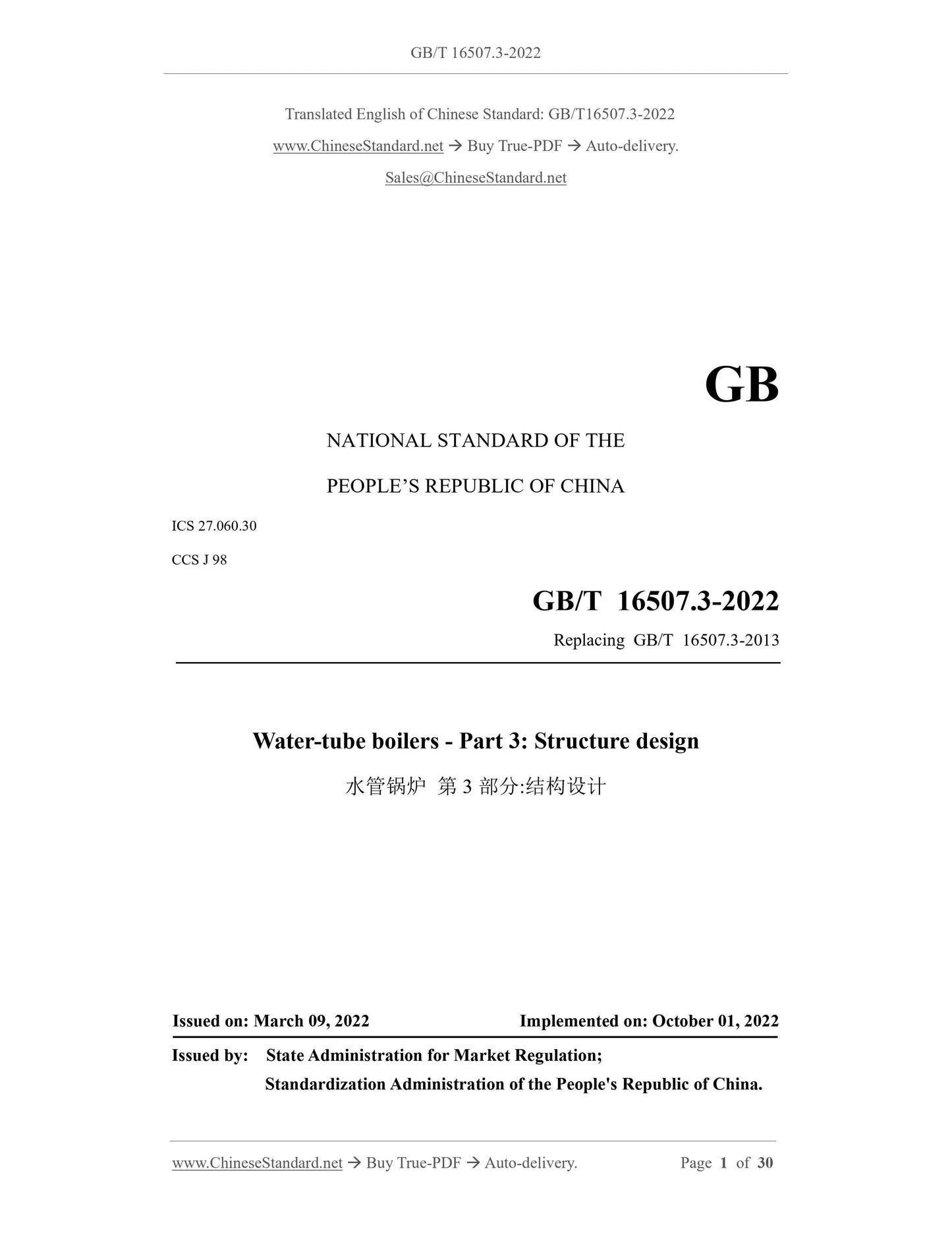
GB/T 16507.3-2022
GB
NATIONAL STANDARD OF THE
PEOPLE’S REPUBLIC OF CHINA
ICS 27.060.30
CCS J 98
Replacing GB/T 16507.3-2013
Water-tube boilers - Part 3: Structure design
ISSUED ON: MARCH 09, 2022
IMPLEMENTED ON: OCTOBER 01, 2022
Issued by: State Administration for Market Regulation;
Standardization Administration of the People's Republic of China.
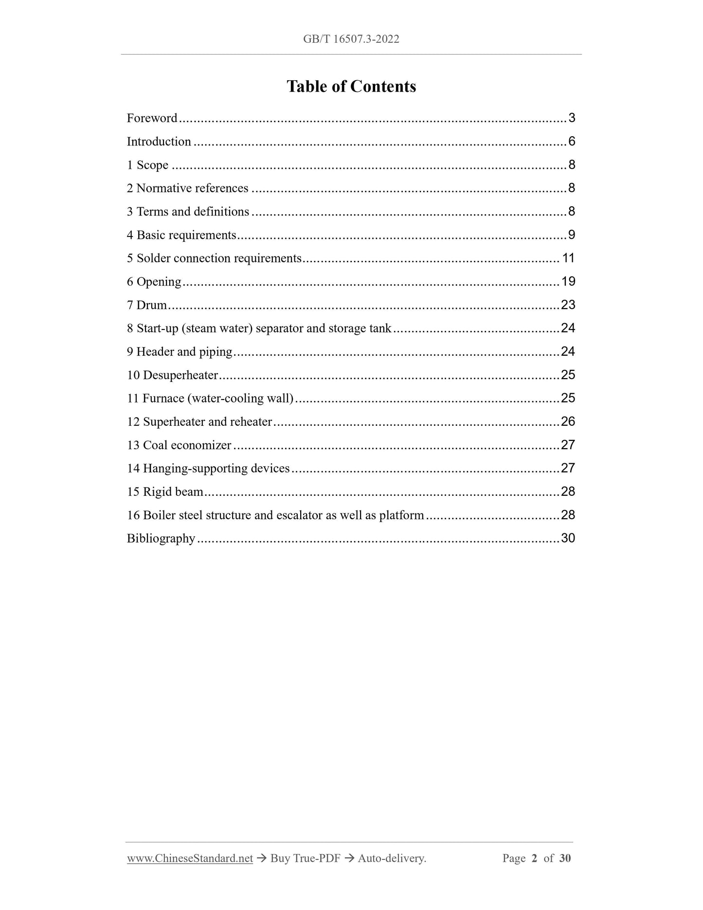
Table of Contents
Foreword ... 3
Introduction ... 6
1 Scope ... 8
2 Normative references ... 8
3 Terms and definitions ... 8
4 Basic requirements ... 9
5 Solder connection requirements ... 11
6 Opening ... 19
7 Drum ... 23
8 Start-up (steam water) separator and storage tank ... 24
9 Header and piping ... 24
10 Desuperheater ... 25
11 Furnace (water-cooling wall) ... 25
12 Superheater and reheater ... 26
13 Coal economizer ... 27
14 Hanging-supporting devices ... 27
15 Rigid beam ... 28
16 Boiler steel structure and escalator as well as platform ... 28
Bibliography ... 30
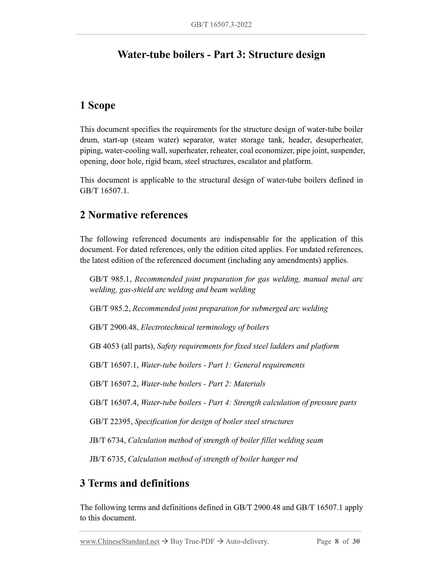
Water-tube boilers - Part 3: Structure design
1 Scope
This document specifies the requirements for the structure design of water-tube boiler
drum, start-up (steam water) separator, water storage tank, header, desuperheater,
piping, water-cooling wall, superheater, reheater, coal economizer, pipe joint, suspender,
opening, door hole, rigid beam, steel structures, escalator and platform.
This document is applicable to the structural design of water-tube boilers defined in
GB/T 16507.1.
2 Normative references
The following referenced documents are indispensable for the application of this
document. For dated references, only the edition cited applies. For undated references,
the latest edition of the referenced document (including any amendments) applies.
GB/T 985.1, Recommended joint preparation for gas welding, manual metal arc
welding, gas-shield arc welding and beam welding
GB/T 985.2, Recommended joint preparation for submerged arc welding
GB/T 2900.48, Electrotechnical terminology of boilers
GB 4053 (all parts), Safety requirements for fixed steel ladders and platform
GB/T 16507.1, Water-tube boilers - Part 1: General requirements
GB/T 16507.2, Water-tube boilers - Part 2: Materials
GB/T 16507.4, Water-tube boilers - Part 4: Strength calculation of pressure parts
GB/T 22395, Specification for design of boiler steel structures
JB/T 6734, Calculation method of strength of boiler fillet welding seam
JB/T 6735, Calculation method of strength of boiler hanger rod
3 Terms and definitions
The following terms and definitions defined in GB/T 2900.48 and GB/T 16507.1 apply
to this document.
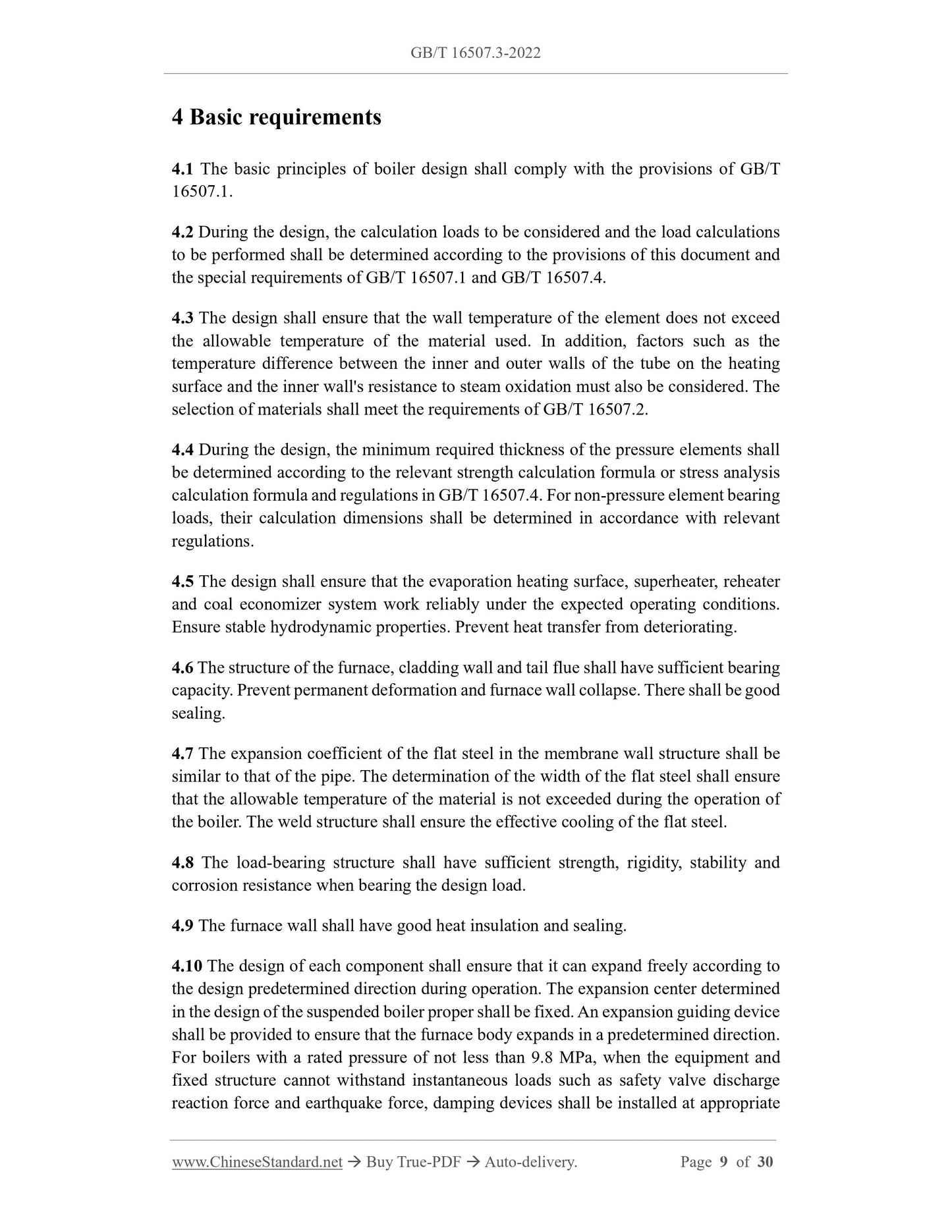
4 Basic requirements
4.1 The basic principles of boiler design shall comply with the provisions of GB/T
16507.1.
4.2 During the design, the calculation loads to be considered and the load calculations
to be performed shall be determined according to the provisions of this document and
the special requirements of GB/T 16507.1 and GB/T 16507.4.
4.3 The design shall ensure that the wall temperature of the element does not exceed
the allowable temperature of the material used. In addition, factors such as the
temperature difference between the inner and outer walls of the tube on the heating
surface and the inner wall's resistance to steam oxidation must also be considered. The
selection of materials shall meet the requirements of GB/T 16507.2.
4.4 During the design, the minimum required thickness of the pressure elements shall
be determined according to the relevant strength calculation formula or stress analysis
calculation formula and regulations in GB/T 16507.4. For non-pressure element bearing
loads, their calculation dimensions shall be determined in accordance with relevant
regulations.
4.5 The design shall ensure that the evaporation heating surface, superheater, reheater
and coal economizer system work reliably under the expected operating conditions.
Ensure stable hydrodynamic properties. Prevent heat transfer from deteriorating.
4.6 The structure of the furnace, cladding wall and tail flue shall have sufficient bearing
capacity. Prevent permanent deformation and furnace wall collapse. There shall be good
sealing.
4.7 The expansion coefficient of the flat steel in the membrane wall structure shall be
similar to that of the pipe. The determination of the width of the flat steel shall ensure
that the allowable temperature of the material is not exceeded during the operation of
the boiler. The weld structure shall ensure the effective cooling of the flat steel.
4.8 The load-bearing structure shall have sufficient strength, rigidity, stability and
corrosion resistance when bearing the design load.
4.9 The furnace wall shall have good heat insulation and sealing.
4.10 The design of each component shall ensure that it can expand freely according to
the design predetermined direction during operation. The expansion center determined
in the design of the suspended boiler proper shall be fixed. An expansion guiding device
shall be provided to ensure that the furnace body expands in a predetermined direction.
For boilers with a rated pressure of not less than 9.8 MPa, when the equipment and
fixed structure cannot withstand instantaneous loads such as safety valve discharge
reaction force and earthquake force, damping devices shall be installed at appropriate
under various startup modes.
4.20 When the DC power station boiler adopts an external start-up (steam-water)
separator to start the system, the working pressure of the isolation valve shall be
determined according to the design pressure under the maximum continuous load. The
strength of the start-up (steam-water) separator is designed and calculated according to
the design parameters of the boiler’s minimum DC load. When the built-in start-up
(steam-water) separator is used to start the system, the strength of each component shall
be calculated according to the design parameters of the maximum continuous load of
the boiler.
4.21 For control circulation boilers, low circulation ratio boilers and supercritical
pressure composite circulation boilers, the layout of the boiler water circulation pump
(starting circulation pump) and its inlet pipes shall prevent vaporization of the working
medium in the pipe and at the pump inlet.
4.22 The pipe clamps, hangers, and clamping pipes on the heating surface shall be set
reasonably and reliably. Prevent overheating, burning, straining and causing pipes to
collide and rub against each other.
4.23 The boiler structure shall be convenient for installation, operation, maintenance
and internal and external cleaning.
5 Solder connection requirements
5.1 The strength calculation of boiler fillet welds shall comply with the provisions of
JB/T 6734.
5.2 The main welds of pressure elements and their adjacent areas shall avoid welding
accessories as much as possible. If it is unavoidable, the weld of welding accessories
may pass through the main weld but shall not terminate in the main weld and its adjacent
area.
5.3 The distance (L) between the centerlines of the butt welds on the pipes on the
heating surface of the boiler (except dissimilar steel joints) and the straight sections of
the pipes shall meet the following requirements:
a) The outer diameter is less than 159mm, L≥2 times the outer diameter;
b) The outer diameter is not less than 159mm, L≥300mm.
When the boiler structure is difficult to meet the above requirements, the heat-affected
zones of the butt welds shall not overlap, and L≥50mm.
5.4 The butt welds of pipes on the heating surface (except for coiled pipes and formed
pipe fittings) shall be located on the straight section of the pipe. The distance from the
center line of the butt weld of the pipe on the heating surface to the outer wall of the
drum and header, the starting point of the pipe bending, and the edge of the pipe support
is at least 50mm. For boilers with a rated working pressure of not less than 3.8MPa, the
distance shall be at least 70mm (except for dissimilar steel joints limited by the
structure).
5.5 The longitudinal and circumferential butt welds of the drum, start-up (steam-water)
separator, water storage tank, header, pipe and pipe, and the splicing weld of the head
shall adopt a full penetration structure.
5.6 The longitudinal welds of two adjacent drum sections on the drum (except for those
with unequal wall thickness), and the splicing welds of the head and the longitudinal
welds of adjacent drum sections shall not be connected to each other. The distance
between the centerlines of the welds (external arc length) shall be at least 3 times the
thickness of the thicker steel plate, and not less than 100mm.
5.7 For a boiler drum formed by pressing and welding two steel plates with unequal
wall thickness, the longitudinal joints of two adjacent drum sections are allowed to be
connected. However, the intersection of welds shall be qualified by radiographic
inspection.
5.8 Generally, the centerlines of the steel plates on both sides of the longitudinal and
circumferential seams of the drum shall be aligned. When the thickness of the steel
plates on both sides of the ring seam of the drum is not equal, the edge of one side is
also allowed to be aligned. When two elements or steel plates with different nominal
thicknesses are butted, if the difference in nominal edge thickness of any of the two
sides exceeds the edge deviation value specified in 5.9, the edge of the thick plate shall
be cut to be flush with the edge of the thin plate. The chamfered surface shall be smooth.
The slope is not greater than 1:3. If necessary, the width of the weld can be calculated
within the slope, as shown in Figure 1.
6.3.1 The number and position of manholes, head holes, hand holes, cleaning holes,
inspection holes and observation holes opened on boiler pressure elements shall meet
the needs of installation, maintenance, operation monitoring and cleaning.
6.3.2 The connection between manhole ring and head hole ring of pressure elements of
the boiler and drum body and head shall adopt full penetration structure.
6.3.3 The manhole cover, head hole cover and hand hole cover on the pressure elements
of the boiler with a rated pressure not less than 3.8MPa shall adopt an internally closed
structure or a welded structure. The manhole cover, head hole cover and hand hole cover
on the pressure elements of the boiler with rated pressure less than 3.8MPa can adopt
flange connection structure.
6.3.4 For boilers with a drum inner diameter not less than 800mm, manholes shall be
provided on the drum body or head. When personnel cannot enter the boiler due to
structural restrictions, only the head hole may be opened. For boilers with an inner
diameter of the drum less than 800mm, at least one head hole shall be provided on the
drum body or head.
6.3.5 The elliptical manhole on the boiler pressure element shall not be less than
280mm×380mm. The diameter of the circular manhole shall not be less than 380mm.
The minimum sealing plane width of the manhole circle is 19mm. The total gap between
the shoulder of the manhole cover and the manhole ring shall not be greater than 3mm
(not more than 1.5mm at each point along the circumference). The depth of the groove
in the cover plate shall be such that it can completely accommodate the gasket.
6.3.6 The elliptical head hole on the boiler pressure element shall not be less than
220mm×320mm. The height of the neck or hole ring shall not be greater than 100mm.
The minimum sealing plane width of the head hole ring is 15mm.
6.3.7 The inner diameter of the upper hand hole of the boiler pressure element shall not
be less than 80mm. The height of the neck or hole ring shall not be greater than 65mm.
The minimum sealing plane width of the hand hole ring is 6mm.
6.3.8 On the boiler pressure element, the inner diameter of the cleaning hole shall not
be less than 50mm. The neck height shall not be greater than 50mm.
6.3.9 Due to structural reasons, when the height of the neck or hole ring exceeds the
requirements in 5.3.6~5.3.8, the size of each hole shall be enlarged appropriately.
6.3.10 When the handhole cover and the hole ring of the header are connected by non-
welding, they shall not be in direct contact with the flame.
6.3.11 For pressure elements that require radiographic inspection of welds, when the
radiation source needs to be placed inside the cylinder for transillumination and there
is no suitable opening for use, a radiographic inspection hole shall be provided.
6.4 Furnace wall door hole
6.4.1 The oval manhole on the furnace wall is generally not less than 400mm×450mm.
The diameter of the circular manhole is generally not less than 450mm. Rectangular
manholes are generally not less than 300mm×400mm.
6.4.2 For boilers with slight positive pressure combustion, the furnace wall, flue and
door openings of various parts shall be reliably sealed. The fire viewing hole shall be
equipped with an interlock device to prevent flame from blowing out.
6.4.3 Manhole doors in furnace walls shall be fitted with strong latches. The hole cover
of the monitoring hole on the furnace wall shall be guaranteed not to be washed away
by the flue gas.
6.4.4 For water-tube boilers burning pulverized coal, oil, gas and other fuels that may
cause deflagration with a rated evaporation capacity not greater than 75t/h, when the
furnace safety automatic protection system is not installed, explosion-proof doors shall
be installed in the furnace and flue. The setting of explosion-proof doors shall not
endanger personal safety.
7 Drum
7.1 The nominal thickness of the drum body shall not be less than 6mm. When the
heating surface tube and the drum are connected by expansion joints, the nominal
thickness of the drum body shall not be less than 12mm. The net distance between the
holes of expansion joints shall not be less than 19mm.
7.2 When the heating surface tube and the drum are connected by expansion joints, the
wall thickness of the tube shall not be greater than 5mm; the outer diameter of the tube
Share
