
1
/
of
5
PayPal, credit cards. Download editable-PDF and invoice in 1 second!
GB/T 17855-2017 English PDF (GBT17855-2017)
GB/T 17855-2017 English PDF (GBT17855-2017)
Regular price
$255.00 USD
Regular price
Sale price
$255.00 USD
Unit price
/
per
Shipping calculated at checkout.
Couldn't load pickup availability
Delivery: 3 seconds. Download true-PDF + Invoice.
Get Quotation: Click GB/T 17855-2017 (Self-service in 1-minute)
Historical versions (Master-website): GB/T 17855-2017
Preview True-PDF (Reload/Scroll-down if blank)
GB/T 17855-2017: Calculation of load capacity of spline
GB/T 17855-2017
Calculation of load capacity of spline
ICS 21.120.30
J18
National Standards of People's Republic of China
Replace GB/T 17855-1999
Calculation method of spline bearing capacity
2017-09-07 released
2018-04-01 implementation
General Administration of Quality Supervision, Inspection and Quarantine of the People's Republic of China
Issued by the National Standardization Administration of China
Preface
This standard was drafted in accordance with the rules given in GB/T 1.1-2009.
This standard replaces GB/T 17855-1999 "Calculation Method for Spline Bearing Capacity". Compared with GB/T 17855-1999, this standard
The main technical changes are as follows.
--- Revise Figure 6 and Figure 7 in the standard.
This standard was proposed and managed by the National Technical Committee for Machine Shafts and Accessories Standardization (SAC/TC109).
Drafting organizations of this standard. AVIC Productivity Promotion Center, Taiyuan Heavy Industry Co., Ltd., AVIC Comprehensive Technology Research Institute, AVIC I
Flying courtyard.
The main drafters of this standard. Ming Cuixin, Wang Xiaoling, Li Haibin, Liu Qiguo, Zhao Huiting.
The previous published versions of the standard replaced by this standard are as follows.
---GB/T 17855-1999.
Calculation method of spline bearing capacity
1 Scope
This standard specifies the calculation method for the bearing capacity of cylindrical straight tooth involute splines and cylindrical rectangular tooth splines (hereinafter referred to as splines).
This standard applies to splines manufactured in accordance with GB/T 1144 and GB/T 3478.1.Other types of splines can also be used as reference.
2 Normative references
The following documents are indispensable for the application of this document. For dated reference documents, only the dated version applies to this article
Pieces. For undated reference documents, the latest version (including all amendments) is applicable to this document.
GB/T 1144 Rectangular spline size, tolerance and inspection
GB/T 3478.1-2008 Cylindrical Straight Tooth Involute Spline (Metric Modular Tooth Side Fit) Part 1.General Introduction
3 Terms and codes
Terms and codes are shown in Table 1.
Table 1 Terms and codes
4.2 Load calculation
4.2.1 The input torque T is calculated according to formula (1).
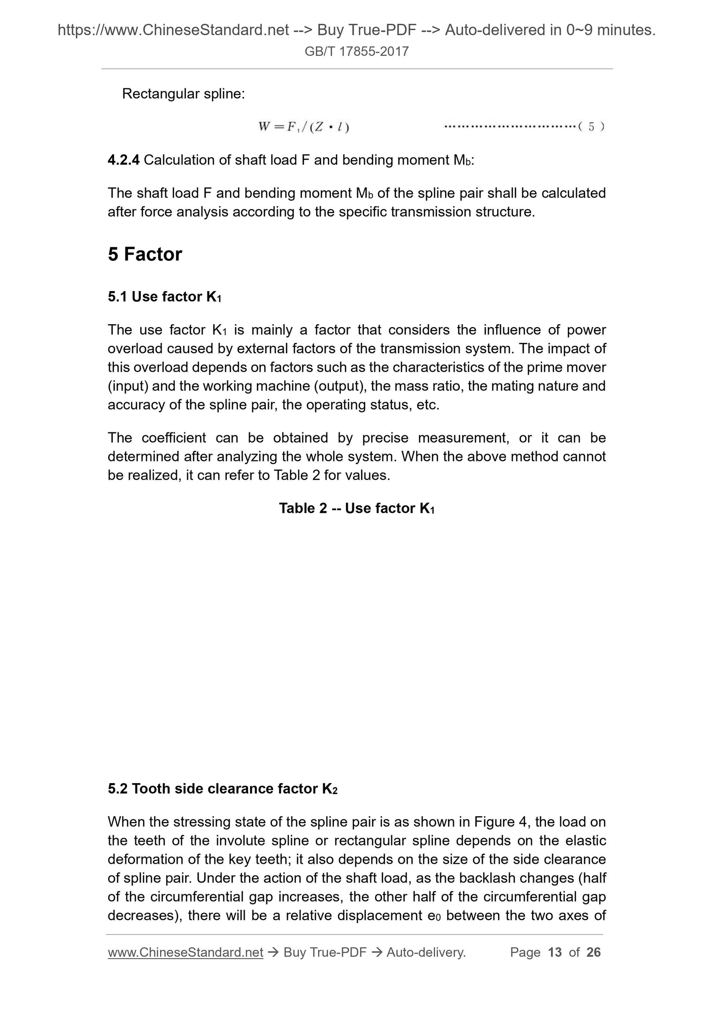
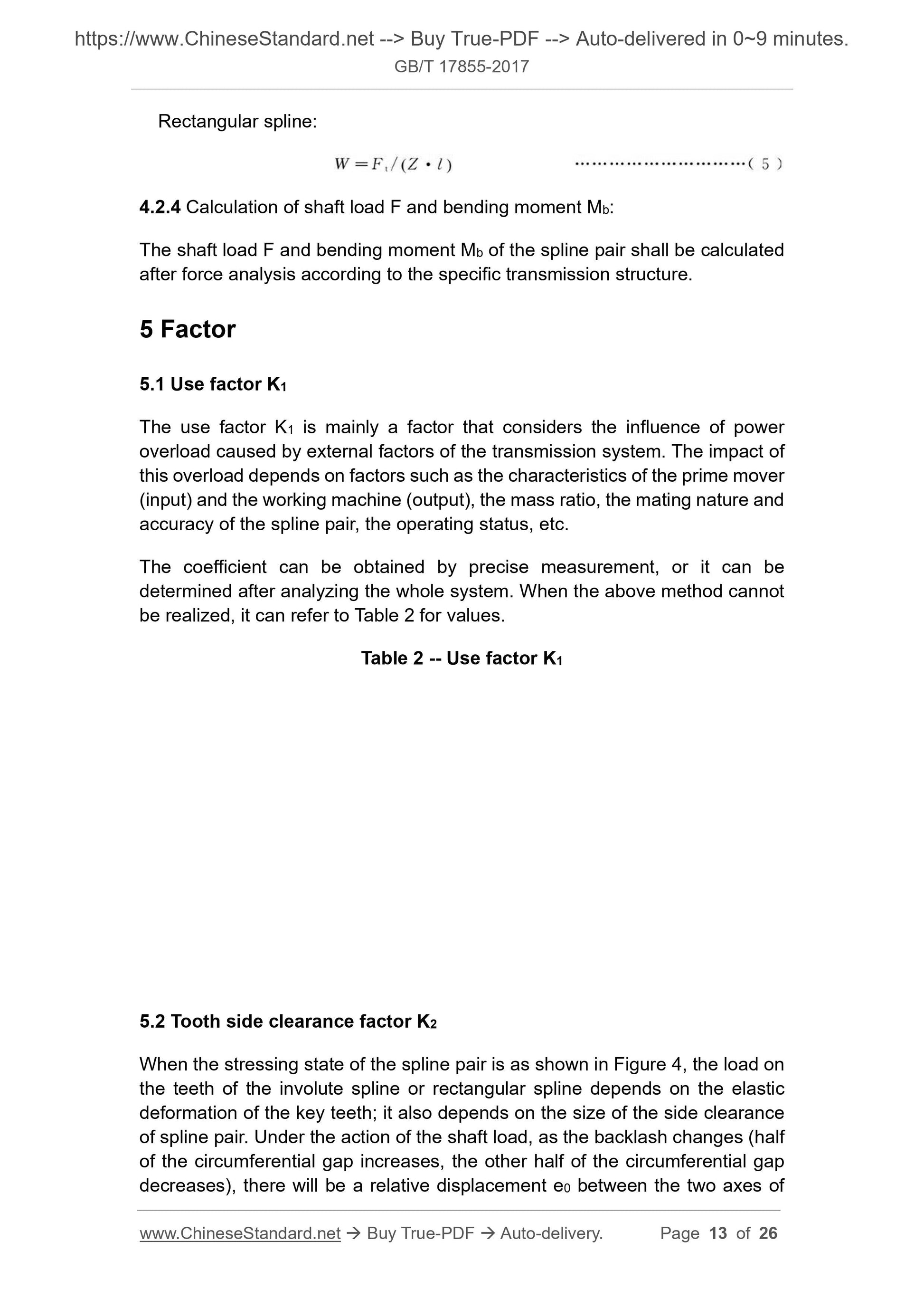
4.2.4 Calculation of final force F and bending moment Mb.
The compression force F and bending moment Mb of the spline pair shall be calculated after force analysis according to the specific transmission structure.
5 factor
5.1 Use factor K1
The use coefficient K1 is mainly a coefficient that considers the influence of power overload caused by external factors of the transmission system. The impact of this overload depends on
Factors such as the characteristics of the prime mover (input end) and the working machine (output end), the mass ratio, the mating nature and accuracy of the spline pair, and the operating status.
The coefficient can be obtained by precise measurement, or it can be determined after analyzing the whole system. When the above method cannot be achieved, you can refer to
Table 2 values.
Table 2 Use factor K1
5.2 Tooth side clearance factor K2
When the force state of the spline pair is shown in Figure 4, the magnitude of the load on each key tooth of the involute spline or rectangular spline is determined by
In addition to the elastic deformation of the key teeth, it also depends on the backlash of the spline pair. Under the action of the final pressure, as the backlash changes (between half of the circumference
The gap increases, and the other half of the circumferential gap decreases), the two axes of the inner spline and the outer spline will have a relative displacement e0, see Figure 4 and Figure 9.its
The magnitude of the displacement e0 is related to factors such as the size of the backlash (gap) of the spline and the manufacturing accuracy. After the displacement is generated, the load is distributed
On fewer key teeth (losing the self-centering effect on the involute spline), it affects the load-carrying capacity of the spline. Interdental
The clearance factor K2 is taken into consideration. Usually K2=1.1~3.0.
When the pressing force is small and the accuracy of the spline pair is high, K2=1.1~1.5 can be selected; when the pressing force is large and the accuracy of the spline pair is low, it can be
Take K2=2.0~3.0; when the pressing force is zero and only bears the torque (see Figure 2), K2=1.0.
5.3 Distribution coefficient K3
When the two axes of the inner spline and the outer spline of the spline pair are coaxial, due to the influence of the cumulative error of the tooth pitch (indexing error), the spline
The theoretical backlash (single tooth backlash) of the pair is different, and the load on each key tooth is also different.
This effect is considered by the distribution coefficient K3.For the spline pair before running-in, when the accuracy is high (according to the GB/T 1144 standard, it is fine
The dense rectangular spline or accuracy level is 5 or higher according to GB/T 3478.1-2008 standard), K3=1.1~1.2; when the accuracy
When it is low (when the rectangular spline is generally used according to GB/T 1144 standard or when the accuracy grade is lower than level 5 according to GB/T 3478.1-2008 standard),
K3=1.3~1.6.For the spline pair after running-in, when each key tooth is involved in the work and the load is basically the same, take K3=1.0.
5.4 Axial eccentric load factor K4
Due to the tooth orientation error generated during the manufacture of the spline pair and the concentricity error after installation, as well as the torsional deformation after loading, the tooth edge of each key
The axial load is uneven. Consider the axial eccentric load factor K4.Its value can be selected from Table 3.
For the spline pair after running-in, when the axial load distribution of each key tooth is basically the same, K4=1.0 can be taken.
When the accuracy of the spline is high and the index circle diameter D or the average circle diameter dm is small, the axial eccentric load factor K4 in Table 3 is taken as the smaller
Value, and vice versa, take the larger value.
Table 3 Axial eccentric load factor K4
6 Carrying capacity calculation
6.1 Calculation of tooth surface contact strength
6.1.1 Tooth surface compressive stress σH is calculated according to formula (6).
6.4 Calculation of tooth surface wear resistance
6.4.1 Calculation of wear resistance of spline pairs when working under 108 cycles
6.4.1.1 Tooth surface compressive stress σH is calculated according to formula (6).
6.4.1.2 See Table 4 for the allowable compressive stress [σH1] value of tooth surface wear.
6.4.1.3 The calculation result should meet the conditions listed in formula (16).
6.4.2 Calculation of wear resistance ability of spline pair under long-term work without wear
6.4.2.1 Tooth surface compressive stress σH is calculated according to formula (6).
6.4.2.2 Refer to Table 5 for the allowable compressive stress [σH2] value of tooth surface wear.
6.4.2.3 The calculation result should meet the conditions listed in formula (17).
6.5 Calculation of torsion and bending strength of external spline
The external spline will produce bending stress σFn and shear stress τtn under the action of torsion, bending and pressing force (usually near the end of the spline
maximum). These two stresses are combined into equivalent stress σV.
The equivalent stress σV is calculated according to formula (18).
Get Quotation: Click GB/T 17855-2017 (Self-service in 1-minute)
Historical versions (Master-website): GB/T 17855-2017
Preview True-PDF (Reload/Scroll-down if blank)
GB/T 17855-2017: Calculation of load capacity of spline
GB/T 17855-2017
Calculation of load capacity of spline
ICS 21.120.30
J18
National Standards of People's Republic of China
Replace GB/T 17855-1999
Calculation method of spline bearing capacity
2017-09-07 released
2018-04-01 implementation
General Administration of Quality Supervision, Inspection and Quarantine of the People's Republic of China
Issued by the National Standardization Administration of China
Preface
This standard was drafted in accordance with the rules given in GB/T 1.1-2009.
This standard replaces GB/T 17855-1999 "Calculation Method for Spline Bearing Capacity". Compared with GB/T 17855-1999, this standard
The main technical changes are as follows.
--- Revise Figure 6 and Figure 7 in the standard.
This standard was proposed and managed by the National Technical Committee for Machine Shafts and Accessories Standardization (SAC/TC109).
Drafting organizations of this standard. AVIC Productivity Promotion Center, Taiyuan Heavy Industry Co., Ltd., AVIC Comprehensive Technology Research Institute, AVIC I
Flying courtyard.
The main drafters of this standard. Ming Cuixin, Wang Xiaoling, Li Haibin, Liu Qiguo, Zhao Huiting.
The previous published versions of the standard replaced by this standard are as follows.
---GB/T 17855-1999.
Calculation method of spline bearing capacity
1 Scope
This standard specifies the calculation method for the bearing capacity of cylindrical straight tooth involute splines and cylindrical rectangular tooth splines (hereinafter referred to as splines).
This standard applies to splines manufactured in accordance with GB/T 1144 and GB/T 3478.1.Other types of splines can also be used as reference.
2 Normative references
The following documents are indispensable for the application of this document. For dated reference documents, only the dated version applies to this article
Pieces. For undated reference documents, the latest version (including all amendments) is applicable to this document.
GB/T 1144 Rectangular spline size, tolerance and inspection
GB/T 3478.1-2008 Cylindrical Straight Tooth Involute Spline (Metric Modular Tooth Side Fit) Part 1.General Introduction
3 Terms and codes
Terms and codes are shown in Table 1.
Table 1 Terms and codes
4.2 Load calculation
4.2.1 The input torque T is calculated according to formula (1).
4.2.4 Calculation of final force F and bending moment Mb.
The compression force F and bending moment Mb of the spline pair shall be calculated after force analysis according to the specific transmission structure.
5 factor
5.1 Use factor K1
The use coefficient K1 is mainly a coefficient that considers the influence of power overload caused by external factors of the transmission system. The impact of this overload depends on
Factors such as the characteristics of the prime mover (input end) and the working machine (output end), the mass ratio, the mating nature and accuracy of the spline pair, and the operating status.
The coefficient can be obtained by precise measurement, or it can be determined after analyzing the whole system. When the above method cannot be achieved, you can refer to
Table 2 values.
Table 2 Use factor K1
5.2 Tooth side clearance factor K2
When the force state of the spline pair is shown in Figure 4, the magnitude of the load on each key tooth of the involute spline or rectangular spline is determined by
In addition to the elastic deformation of the key teeth, it also depends on the backlash of the spline pair. Under the action of the final pressure, as the backlash changes (between half of the circumference
The gap increases, and the other half of the circumferential gap decreases), the two axes of the inner spline and the outer spline will have a relative displacement e0, see Figure 4 and Figure 9.its
The magnitude of the displacement e0 is related to factors such as the size of the backlash (gap) of the spline and the manufacturing accuracy. After the displacement is generated, the load is distributed
On fewer key teeth (losing the self-centering effect on the involute spline), it affects the load-carrying capacity of the spline. Interdental
The clearance factor K2 is taken into consideration. Usually K2=1.1~3.0.
When the pressing force is small and the accuracy of the spline pair is high, K2=1.1~1.5 can be selected; when the pressing force is large and the accuracy of the spline pair is low, it can be
Take K2=2.0~3.0; when the pressing force is zero and only bears the torque (see Figure 2), K2=1.0.
5.3 Distribution coefficient K3
When the two axes of the inner spline and the outer spline of the spline pair are coaxial, due to the influence of the cumulative error of the tooth pitch (indexing error), the spline
The theoretical backlash (single tooth backlash) of the pair is different, and the load on each key tooth is also different.
This effect is considered by the distribution coefficient K3.For the spline pair before running-in, when the accuracy is high (according to the GB/T 1144 standard, it is fine
The dense rectangular spline or accuracy level is 5 or higher according to GB/T 3478.1-2008 standard), K3=1.1~1.2; when the accuracy
When it is low (when the rectangular spline is generally used according to GB/T 1144 standard or when the accuracy grade is lower than level 5 according to GB/T 3478.1-2008 standard),
K3=1.3~1.6.For the spline pair after running-in, when each key tooth is involved in the work and the load is basically the same, take K3=1.0.
5.4 Axial eccentric load factor K4
Due to the tooth orientation error generated during the manufacture of the spline pair and the concentricity error after installation, as well as the torsional deformation after loading, the tooth edge of each key
The axial load is uneven. Consider the axial eccentric load factor K4.Its value can be selected from Table 3.
For the spline pair after running-in, when the axial load distribution of each key tooth is basically the same, K4=1.0 can be taken.
When the accuracy of the spline is high and the index circle diameter D or the average circle diameter dm is small, the axial eccentric load factor K4 in Table 3 is taken as the smaller
Value, and vice versa, take the larger value.
Table 3 Axial eccentric load factor K4
6 Carrying capacity calculation
6.1 Calculation of tooth surface contact strength
6.1.1 Tooth surface compressive stress σH is calculated according to formula (6).
6.4 Calculation of tooth surface wear resistance
6.4.1 Calculation of wear resistance of spline pairs when working under 108 cycles
6.4.1.1 Tooth surface compressive stress σH is calculated according to formula (6).
6.4.1.2 See Table 4 for the allowable compressive stress [σH1] value of tooth surface wear.
6.4.1.3 The calculation result should meet the conditions listed in formula (16).
6.4.2 Calculation of wear resistance ability of spline pair under long-term work without wear
6.4.2.1 Tooth surface compressive stress σH is calculated according to formula (6).
6.4.2.2 Refer to Table 5 for the allowable compressive stress [σH2] value of tooth surface wear.
6.4.2.3 The calculation result should meet the conditions listed in formula (17).
6.5 Calculation of torsion and bending strength of external spline
The external spline will produce bending stress σFn and shear stress τtn under the action of torsion, bending and pressing force (usually near the end of the spline
maximum). These two stresses are combined into equivalent stress σV.
The equivalent stress σV is calculated according to formula (18).
Share