1
/
of
11
www.ChineseStandard.us -- Field Test Asia Pte. Ltd.
GB/T 20948-2007 English PDF (GB/T20948-2007)
GB/T 20948-2007 English PDF (GB/T20948-2007)
Regular price
$150.00
Regular price
Sale price
$150.00
Unit price
/
per
Shipping calculated at checkout.
Couldn't load pickup availability
GB/T 20948-2007: Rear-view mirrors requirements for agricultural and forestry tractors
Delivery: 9 seconds. Download (& Email) true-PDF + Invoice.
Get Quotation: Click GB/T 20948-2007 (Self-service in 1-minute)
Historical versions (Master-website): GB/T 20948-2007
Preview True-PDF (Reload/Scroll-down if blank)
GB/T 20948-2007
NATIONAL STANDARD OF THE
PEOPLE’S REPUBLIC OF CHINA
ICS 65.060.10
T 68
Rear-view mirrors requirements for
agricultural and forestry tractors
ISSUED ON: JUNE 25, 2007
IMPLEMENTED ON: NOVEMBER 1, 2007
Issued by: General Administration of Quality Supervision, Inspection
and Quarantine of the People’s Republic of China;
Standardization Administration of the People's Republic of
China.
Table of Contents
Foreword ... 3
1 Scope ... 4
2 Normative references ... 4
3 Terms ... 4
4 Performance requirements ... 7
5 Installation requirements ... 11
6 Measurement and devices and test methods ... 12
7 Inspection rules ... 24
8 Marking, packaging, transportation and storage ... 26
Appendix A (Normative) Spectral tristimulus values of the CIE standard
colorimetric observer ... 28
Rear-view mirrors requirements for
agricultural and forestry tractors
1 Scope
This Standard specifies the definitions, performance requirements,
installation requirements, test methods, inspection rules and marking,
packaging, transportation and storage of rear-view mirrors for agricultural and
forestry wheeled and crawler tractors.
This Standard applies to the agricultural and forestry wheeled and crawler
tractors.
2 Normative references
The provisions in the following documents become the provisions of this
Standard through reference in this Standard. For dated references, the
subsequent amendments (excluding corrections) or revisions do not apply to
this Standard. However, parties who reach an agreement based on this
Standard are encouraged to study if the latest editions of these documents
are applicable. For undated references, the latest editions apply to this
Standard.
QC/T 625-1999 Metallic coatings and conversion coatings for automobile
QC/T 484-1999 Automobile paint coatings
ISO 5353:1995 Earth-moving machinery, and tractors and machinery for
agriculture and forestry - Seat index point
3 Terms
The following terms and definitions are applicable to this Standard.
3.1 Rear-view mirror
A device that is able to see the rear and side images of the tractor within the
vision specified in 3.10.
3.2 Interior rear-view mirror
A device that meets the vision defined in 3.1 and is mounted in the tractor
cab.
3.3 Exterior rear-view mirror
A device that meets the vision defined in 3.1 and is mounted on the outer
surface of the tractor.
3.4 Class of rear-view mirror
Various rear-view mirrors with one or more common features or functions.
Class I is an interior rear-view mirror; and Class II is an exterior rear-view
mirror.
3.5 Center of the mirror
The center of mass of the visible area on the reflecting surface.
3.6 Principal radius of curvature at one point obtained on the
reflecting surface (ri, ri’)
The radius of curvature measured by the instrument specified in 6.3.1 through
the center of the reflecting surface, parallel to the line segment b of the mirror
and perpendicular to the direction of the line. See 4.3.1.2 for the
determination of line segment b.
3.7 Radius of curvature at one point on the reflecting surface (rpi)
Refer to the arithmetic mean value of the principal radius of curvature:
Where:
rpi - Radius of curvature at the ith point, in millimeters (mm);
ri, ri’ - Principal radius of curvature measured in two mutually perpendicular
directions at the ith point, in millimeters (mm).
3.8 Radius of curvature of the constituent parts of the rear-view mirror
(C)
C refers to the radius of the arc of the curved shape of the components such
as protective frame, support frame, and connecting member of the rear-view
mirror.
3.9 Driver’s ocular points
4.1.5 For the edge of the fixed hole or recess with a diameter or a maximum
diagonal of less than 12mm on the rear-view mirror, if it has been rounded,
the requirements for radius of curvature in 4.1.4 are not necessarily met.
4.1.6 The connection of the rear-view mirror to the tractor is designed to
ensure that the rear-view mirror is offset from the axis of rotation or the center
of rotation in the direction of impact, or either of them, to form a cylinder with a
radius of 50mm. The cylinder shall be cut at least to the surface portion to
which the connector is attached.
4.1.7 For exterior rear-view mirrors, if the parts involved in 4.1.3, 4.1.4, and
4.1.5 are made of materials not greater than Shore hardness of A60, it is not
necessary to meet the above requirements.
4.1.8 For interior rear-view mirrors, if the parts on the rear-view mirrors are
made of materials less than Shore hardness of A50 and mounted on a steel
support, the tests of 4.1.3 and 4.1.4 apply only to this support.
4.2 Appearance requirements
4.2.1 Under the illumination condition of 500 lx, when the mirror surface is
viewed from the 45° direction at 500mm from the naked eye, there shall be no
defects such as deformation, blur, streaks, bubbles, scratches, cracks and
inclusions on the rear-view mirror surface.
4.2.2 Rubber parts shall not have obvious defects such as damages and
cracks.
4.2.3 Plastic parts shall not have obvious defects such as fading, cracks,
scratches and deformation.
4.3 Performance requirements
4.3.1 Size requirements
4.3.1.1 Interior rear-view mirror (Class I)
It shall be possible to draw a rectangle with a base of a and a height of 40mm
on the reflecting surface. The size a is calculated according to the Formula
(2).
Where:
4.4.3.2 The difference between rpi (rp1, rp2 and rp3) value and r value of the
radius of curvature at any point shall be no more than 0.15r.
4.5 Reflectance
4.5.1 The reflectance value determined according to the method specified in
6.4 shall be not less than 40%. If the rear-view mirror has two working
positions (daytime and nighttime), the color signal of road traffic shall be
correctly recognized when it is in the daytime position, and the reflectance
value at nighttime position shall be no less than 4%.
4.5.2 Except for long-term rear-view mirrors under extremely harsh weather
conditions, the reflectance shall meet the reflectance values specified in 4.5.1
during normal use.
4.6 Impact resistance and bending resistance
4.6.1 The rear-view mirrors shall be subjected to an anti-impact test in
accordance with 6.5 and subjected to an anti-bending test in accordance with
6.6.
4.6.2 When the rear-view mirror performs the anti-impact test specified in
6.5 and the anti-bending test specified in 6.6, the reflecting surface shall not
be broken, but the following two conditions may be considered as meeting the
requirements:
4.6.2.1 The shards of glass remain attached to the protective casing or to
objects that are firmly attached to the protective casing. The glass is allowed
to partially detach from the above portion, but the length of any side of the
rupture shall not exceed 2.5mm. At the point of impact, small shards are
allowed to detach from the above portion.
4.6.2.2 The reflecting surface is made of safety glass.
4.6.3 For the rear-view mirror attached to the windshield glass, if the
support member of the rear-view mirror is damaged during the impact test,
the residual part of the protruding base shall be no more than 10mm, and the
shape shall still meet the requirements of 4.1.4 and 4.6.2.
4.7 Vibration resistance
When the vibration resistance of the rear-view mirror is tested in accordance
with the provisions of 6.7, each component shall be free from deformation,
damage, or detachment, which may affect its function. The mirror direction
shall be kept in the original normal operation position.
4.8 Moisture resistance
5.2 Position
5.2.1 The position of the exterior rear-view mirror shall be such that the
driver can clearly see the vision defined in 5.4 when sitting in the seat while
driving normally.
5.2.2 The rear-view mirror shall be visible from the part of the windshield
wiper that is not operating, or from the side window of the tractor (if installed).
5.2.3 In the case of the maximum operation mass of the tractor, if the
bottom edge of the rear-view mirror is less than 2m from the ground, the
installation protrusion of the rear-view mirror shall be no more than 0.20m of
the total width of the tractor.
5.3 Adjustment
5.3.1 The interior rear-view mirror shall enable the driver to make
adjustments at the driving position.
5.3.2 The exterior rear-view mirror shall enable the driver’s arm to make
adjustments by extending out of the tractor or outside the window.
5.4 Vision
5.4.1 Interior rear-view mirror (Class I)
The driver shall be able to see at least a vision area with a width of at least
20m on the horizontal road with the aid of the interior rear-view mirror. The
center plane is the longitudinal reference plane of the tractor and extends
from 60m behind the driver’s ocular points to the horizon, as shown in Figure
9.
5.4.2 Exterior rear-view mirror (Class II)
The driver shall be able to see a vision area with a left and right width of at
least 4m on the horizontal road with the aid of the exterior rear-view mirror.
The left and right sides are parallel to the plane of the longitudinal reference
plane of the tractor and are tangent to the left and right outermost points of
the tractor, and extend from 20m behind the driver’s ocular points to the
horizon. In addition, the driver shall be able to see a vision area with a width
of 1m and connected with the above area from 4m behind the driver’s ocular
points with the aid of the exterior rear-view mirror, as shown in Figure 10.
6 Measurement and devices and test methods
6.1 Measurement of the radius of curvature “C” of the protective frame
the sum of the regular reflectance and the diffuse reflectance.
6.4.1.3 Spectral characteristics of light sources and photodetectors
a) The light source consists of a CIE standard light source A and a lens that
enables the light from the light source to be a parallel beam. In order to
keep the light source voltage stable while the instrument is operating, a
regulated power supply shall be used.
b) The spectral response of the photodetector carried by the receiving unit is
proportional to the appropriate brightness function of the CIE (1931)
standard colorimetric observer (SEE Appendix A). Other combinations of
illuminator-filter-receiver that produce effects that are fully equivalent to
CIE standard illuminator A and daylight vision may also be used. When an
optical integrating sphere is used in the receiving unit, the inner surface of
the sphere shall be coated with a matt (diffusely reflective), non-spectral
selective, white paint.
6.4.1.4 Geometric conditions
a) The incident beam angle (θ) is preferably 0.44 rad ± 0.09 rad (25° ± 5°)
from the perpendicular line perpendicular to the surface of the rear-view
mirror, and shall not exceed the upper limit (0.53 rad or 30°). The angle (θ)
of the receiver axis to the perpendicular line shall be equal to the incident
beam angle (as shown in Figure 5). The diameter of the incident beam on
the test surface shall be not less than 19mm. The area of the reflected
beam covering the photodetector shall be less than the photosensitive
area, but shall be no less than 50% of the photosensitive area, and as
close as possible to the coverage area of the instrument during
calibration.
b) When the optical integrating sphere is used for the receiving unit, the
diameter of the sphere shall be no less than 127mm. On the sphere, the
aperture of the incident beam of the rear-view mirror and the ball wall
shall pass all of the incident beam and the reflected beam. The
photodetector shall be placed in a position that is not exposed to incident
and reflected beams.
6.4.1.5 Electrical characteristic of the photodetector, i.e., indicating
meter device
On the indicating meter, the reading output by the photodetector is a linear
function of the brightness on the photosensitive area. In order to facilitate
zeroing and calibration, light, electricity or a combination of light and
electricity may be used, but the method shall not affect the linearity and
spectral characteristics of the instrument. The accuracy of the receiver, i.e.,
indicating system shall be within ±2% of full scale or within ±10% of the
reading, whichever is less.
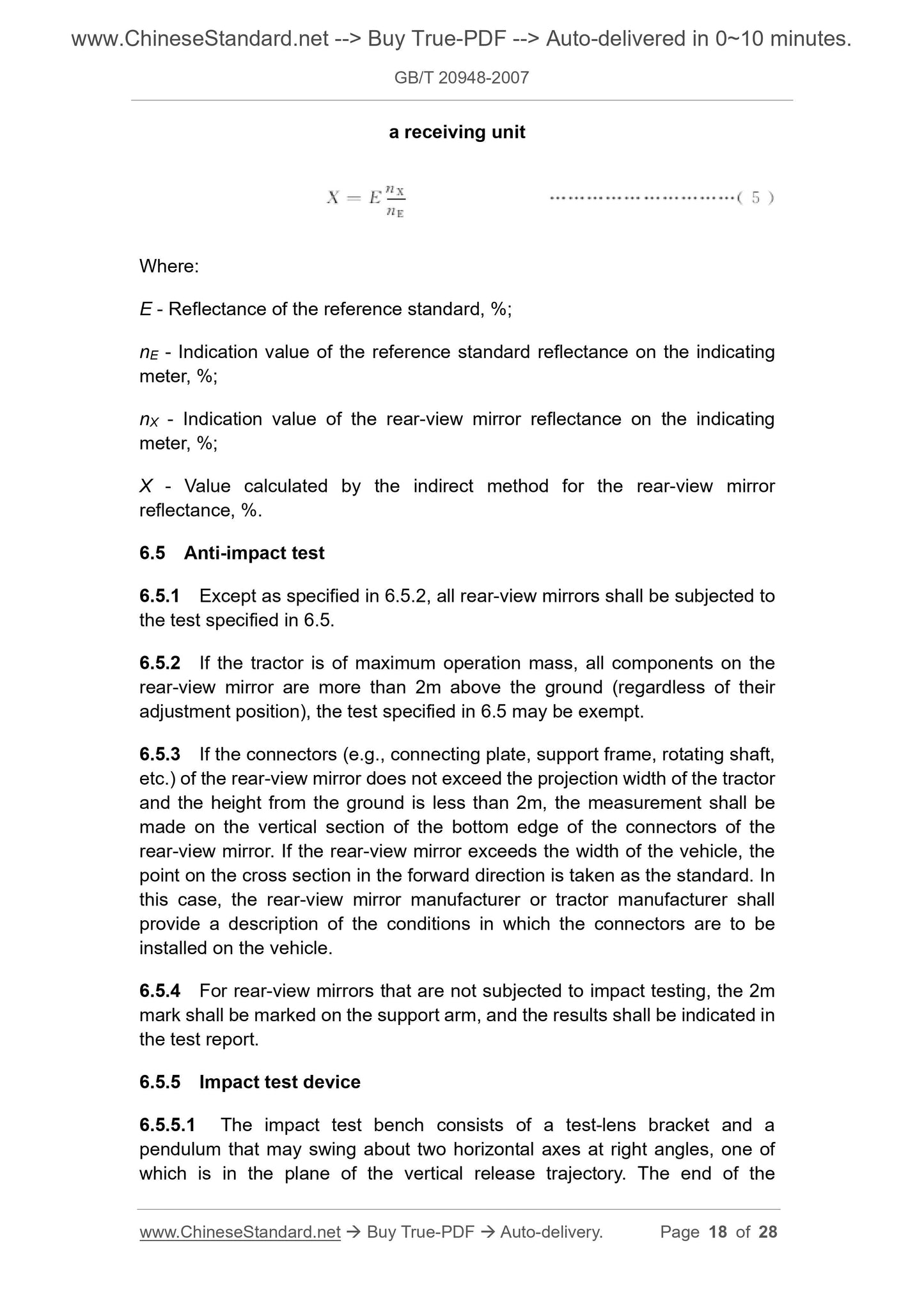
a receiving unit
Where:
E - Reflectance of the reference standard, %;
nE - Indication value of the reference standard reflectance on the indicating
meter, %;
nX - Indication value of the rear-view mirror reflectance on the indicating
meter, %;
X - Value calculated by the indirect method for the rear-view mirror
reflectance, %.
6.5 Anti-impact test
6.5.1 Except as specified in 6.5.2, all rear-view mirrors shall be subjected to
the test specified in 6.5.
6.5.2 If the tractor is of maximum operation mass, all components on the
rear-view mirror are more than 2m above the ground (regardless of their
adjustment position), the test specified in 6.5 may be exempt.
6.5.3 If the connectors (e.g., connecting plate, support frame, rotating shaft,
etc.) of the rear-view mirror does not exceed the projection width of the tractor
and the height from the ground is less than 2m, the measurement shall be
made on the vertical section of the bottom edge of the connectors of the
rear-view mirror. If the rear-view mirror exceeds the width of the vehicle, the
point on the cross section in the forward direction is taken as the standard. In
this case, the rear-view mirror manufacturer or tractor manufacturer shall
provide a description of the conditions in which the connectors are to be
installed on the vehicle.
6.5.4 For rear-view mirrors that are not subjected to impact testing, the 2m
mark shall be marked on the support arm, and the results shall be indicated in
the test report.
6.5.5 Impact test device
6.5.5.1 The impact test bench consists of a test-lens bracket and a
pendulum that may swing about two horizontal axes at right angles, one of
Delivery: 9 seconds. Download (& Email) true-PDF + Invoice.
Get Quotation: Click GB/T 20948-2007 (Self-service in 1-minute)
Historical versions (Master-website): GB/T 20948-2007
Preview True-PDF (Reload/Scroll-down if blank)
GB/T 20948-2007
NATIONAL STANDARD OF THE
PEOPLE’S REPUBLIC OF CHINA
ICS 65.060.10
T 68
Rear-view mirrors requirements for
agricultural and forestry tractors
ISSUED ON: JUNE 25, 2007
IMPLEMENTED ON: NOVEMBER 1, 2007
Issued by: General Administration of Quality Supervision, Inspection
and Quarantine of the People’s Republic of China;
Standardization Administration of the People's Republic of
China.
Table of Contents
Foreword ... 3
1 Scope ... 4
2 Normative references ... 4
3 Terms ... 4
4 Performance requirements ... 7
5 Installation requirements ... 11
6 Measurement and devices and test methods ... 12
7 Inspection rules ... 24
8 Marking, packaging, transportation and storage ... 26
Appendix A (Normative) Spectral tristimulus values of the CIE standard
colorimetric observer ... 28
Rear-view mirrors requirements for
agricultural and forestry tractors
1 Scope
This Standard specifies the definitions, performance requirements,
installation requirements, test methods, inspection rules and marking,
packaging, transportation and storage of rear-view mirrors for agricultural and
forestry wheeled and crawler tractors.
This Standard applies to the agricultural and forestry wheeled and crawler
tractors.
2 Normative references
The provisions in the following documents become the provisions of this
Standard through reference in this Standard. For dated references, the
subsequent amendments (excluding corrections) or revisions do not apply to
this Standard. However, parties who reach an agreement based on this
Standard are encouraged to study if the latest editions of these documents
are applicable. For undated references, the latest editions apply to this
Standard.
QC/T 625-1999 Metallic coatings and conversion coatings for automobile
QC/T 484-1999 Automobile paint coatings
ISO 5353:1995 Earth-moving machinery, and tractors and machinery for
agriculture and forestry - Seat index point
3 Terms
The following terms and definitions are applicable to this Standard.
3.1 Rear-view mirror
A device that is able to see the rear and side images of the tractor within the
vision specified in 3.10.
3.2 Interior rear-view mirror
A device that meets the vision defined in 3.1 and is mounted in the tractor
cab.
3.3 Exterior rear-view mirror
A device that meets the vision defined in 3.1 and is mounted on the outer
surface of the tractor.
3.4 Class of rear-view mirror
Various rear-view mirrors with one or more common features or functions.
Class I is an interior rear-view mirror; and Class II is an exterior rear-view
mirror.
3.5 Center of the mirror
The center of mass of the visible area on the reflecting surface.
3.6 Principal radius of curvature at one point obtained on the
reflecting surface (ri, ri’)
The radius of curvature measured by the instrument specified in 6.3.1 through
the center of the reflecting surface, parallel to the line segment b of the mirror
and perpendicular to the direction of the line. See 4.3.1.2 for the
determination of line segment b.
3.7 Radius of curvature at one point on the reflecting surface (rpi)
Refer to the arithmetic mean value of the principal radius of curvature:
Where:
rpi - Radius of curvature at the ith point, in millimeters (mm);
ri, ri’ - Principal radius of curvature measured in two mutually perpendicular
directions at the ith point, in millimeters (mm).
3.8 Radius of curvature of the constituent parts of the rear-view mirror
(C)
C refers to the radius of the arc of the curved shape of the components such
as protective frame, support frame, and connecting member of the rear-view
mirror.
3.9 Driver’s ocular points
4.1.5 For the edge of the fixed hole or recess with a diameter or a maximum
diagonal of less than 12mm on the rear-view mirror, if it has been rounded,
the requirements for radius of curvature in 4.1.4 are not necessarily met.
4.1.6 The connection of the rear-view mirror to the tractor is designed to
ensure that the rear-view mirror is offset from the axis of rotation or the center
of rotation in the direction of impact, or either of them, to form a cylinder with a
radius of 50mm. The cylinder shall be cut at least to the surface portion to
which the connector is attached.
4.1.7 For exterior rear-view mirrors, if the parts involved in 4.1.3, 4.1.4, and
4.1.5 are made of materials not greater than Shore hardness of A60, it is not
necessary to meet the above requirements.
4.1.8 For interior rear-view mirrors, if the parts on the rear-view mirrors are
made of materials less than Shore hardness of A50 and mounted on a steel
support, the tests of 4.1.3 and 4.1.4 apply only to this support.
4.2 Appearance requirements
4.2.1 Under the illumination condition of 500 lx, when the mirror surface is
viewed from the 45° direction at 500mm from the naked eye, there shall be no
defects such as deformation, blur, streaks, bubbles, scratches, cracks and
inclusions on the rear-view mirror surface.
4.2.2 Rubber parts shall not have obvious defects such as damages and
cracks.
4.2.3 Plastic parts shall not have obvious defects such as fading, cracks,
scratches and deformation.
4.3 Performance requirements
4.3.1 Size requirements
4.3.1.1 Interior rear-view mirror (Class I)
It shall be possible to draw a rectangle with a base of a and a height of 40mm
on the reflecting surface. The size a is calculated according to the Formula
(2).
Where:
4.4.3.2 The difference between rpi (rp1, rp2 and rp3) value and r value of the
radius of curvature at any point shall be no more than 0.15r.
4.5 Reflectance
4.5.1 The reflectance value determined according to the method specified in
6.4 shall be not less than 40%. If the rear-view mirror has two working
positions (daytime and nighttime), the color signal of road traffic shall be
correctly recognized when it is in the daytime position, and the reflectance
value at nighttime position shall be no less than 4%.
4.5.2 Except for long-term rear-view mirrors under extremely harsh weather
conditions, the reflectance shall meet the reflectance values specified in 4.5.1
during normal use.
4.6 Impact resistance and bending resistance
4.6.1 The rear-view mirrors shall be subjected to an anti-impact test in
accordance with 6.5 and subjected to an anti-bending test in accordance with
6.6.
4.6.2 When the rear-view mirror performs the anti-impact test specified in
6.5 and the anti-bending test specified in 6.6, the reflecting surface shall not
be broken, but the following two conditions may be considered as meeting the
requirements:
4.6.2.1 The shards of glass remain attached to the protective casing or to
objects that are firmly attached to the protective casing. The glass is allowed
to partially detach from the above portion, but the length of any side of the
rupture shall not exceed 2.5mm. At the point of impact, small shards are
allowed to detach from the above portion.
4.6.2.2 The reflecting surface is made of safety glass.
4.6.3 For the rear-view mirror attached to the windshield glass, if the
support member of the rear-view mirror is damaged during the impact test,
the residual part of the protruding base shall be no more than 10mm, and the
shape shall still meet the requirements of 4.1.4 and 4.6.2.
4.7 Vibration resistance
When the vibration resistance of the rear-view mirror is tested in accordance
with the provisions of 6.7, each component shall be free from deformation,
damage, or detachment, which may affect its function. The mirror direction
shall be kept in the original normal operation position.
4.8 Moisture resistance
5.2 Position
5.2.1 The position of the exterior rear-view mirror shall be such that the
driver can clearly see the vision defined in 5.4 when sitting in the seat while
driving normally.
5.2.2 The rear-view mirror shall be visible from the part of the windshield
wiper that is not operating, or from the side window of the tractor (if installed).
5.2.3 In the case of the maximum operation mass of the tractor, if the
bottom edge of the rear-view mirror is less than 2m from the ground, the
installation protrusion of the rear-view mirror shall be no more than 0.20m of
the total width of the tractor.
5.3 Adjustment
5.3.1 The interior rear-view mirror shall enable the driver to make
adjustments at the driving position.
5.3.2 The exterior rear-view mirror shall enable the driver’s arm to make
adjustments by extending out of the tractor or outside the window.
5.4 Vision
5.4.1 Interior rear-view mirror (Class I)
The driver shall be able to see at least a vision area with a width of at least
20m on the horizontal road with the aid of the interior rear-view mirror. The
center plane is the longitudinal reference plane of the tractor and extends
from 60m behind the driver’s ocular points to the horizon, as shown in Figure
9.
5.4.2 Exterior rear-view mirror (Class II)
The driver shall be able to see a vision area with a left and right width of at
least 4m on the horizontal road with the aid of the exterior rear-view mirror.
The left and right sides are parallel to the plane of the longitudinal reference
plane of the tractor and are tangent to the left and right outermost points of
the tractor, and extend from 20m behind the driver’s ocular points to the
horizon. In addition, the driver shall be able to see a vision area with a width
of 1m and connected with the above area from 4m behind the driver’s ocular
points with the aid of the exterior rear-view mirror, as shown in Figure 10.
6 Measurement and devices and test methods
6.1 Measurement of the radius of curvature “C” of the protective frame
the sum of the regular reflectance and the diffuse reflectance.
6.4.1.3 Spectral characteristics of light sources and photodetectors
a) The light source consists of a CIE standard light source A and a lens that
enables the light from the light source to be a parallel beam. In order to
keep the light source voltage stable while the instrument is operating, a
regulated power supply shall be used.
b) The spectral response of the photodetector carried by the receiving unit is
proportional to the appropriate brightness function of the CIE (1931)
standard colorimetric observer (SEE Appendix A). Other combinations of
illuminator-filter-receiver that produce effects that are fully equivalent to
CIE standard illuminator A and daylight vision may also be used. When an
optical integrating sphere is used in the receiving unit, the inner surface of
the sphere shall be coated with a matt (diffusely reflective), non-spectral
selective, white paint.
6.4.1.4 Geometric conditions
a) The incident beam angle (θ) is preferably 0.44 rad ± 0.09 rad (25° ± 5°)
from the perpendicular line perpendicular to the surface of the rear-view
mirror, and shall not exceed the upper limit (0.53 rad or 30°). The angle (θ)
of the receiver axis to the perpendicular line shall be equal to the incident
beam angle (as shown in Figure 5). The diameter of the incident beam on
the test surface shall be not less than 19mm. The area of the reflected
beam covering the photodetector shall be less than the photosensitive
area, but shall be no less than 50% of the photosensitive area, and as
close as possible to the coverage area of the instrument during
calibration.
b) When the optical integrating sphere is used for the receiving unit, the
diameter of the sphere shall be no less than 127mm. On the sphere, the
aperture of the incident beam of the rear-view mirror and the ball wall
shall pass all of the incident beam and the reflected beam. The
photodetector shall be placed in a position that is not exposed to incident
and reflected beams.
6.4.1.5 Electrical characteristic of the photodetector, i.e., indicating
meter device
On the indicating meter, the reading output by the photodetector is a linear
function of the brightness on the photosensitive area. In order to facilitate
zeroing and calibration, light, electricity or a combination of light and
electricity may be used, but the method shall not affect the linearity and
spectral characteristics of the instrument. The accuracy of the receiver, i.e.,
indicating system shall be within ±2% of full scale or within ±10% of the
reading, whichever is less.
a receiving unit
Where:
E - Reflectance of the reference standard, %;
nE - Indication value of the reference standard reflectance on the indicating
meter, %;
nX - Indication value of the rear-view mirror reflectance on the indicating
meter, %;
X - Value calculated by the indirect method for the rear-view mirror
reflectance, %.
6.5 Anti-impact test
6.5.1 Except as specified in 6.5.2, all rear-view mirrors shall be subjected to
the test specified in 6.5.
6.5.2 If the tractor is of maximum operation mass, all components on the
rear-view mirror are more than 2m above the ground (regardless of their
adjustment position), the test specified in 6.5 may be exempt.
6.5.3 If the connectors (e.g., connecting plate, support frame, rotating shaft,
etc.) of the rear-view mirror does not exceed the projection width of the tractor
and the height from the ground is less than 2m, the measurement shall be
made on the vertical section of the bottom edge of the connectors of the
rear-view mirror. If the rear-view mirror exceeds the width of the vehicle, the
point on the cross section in the forward direction is taken as the standard. In
this case, the rear-view mirror manufacturer or tractor manufacturer shall
provide a description of the conditions in which the connectors are to be
installed on the vehicle.
6.5.4 For rear-view mirrors that are not subjected to impact testing, the 2m
mark shall be marked on the support arm, and the results shall be indicated in
the test report.
6.5.5 Impact test device
6.5.5.1 The impact test bench consists of a test-lens bracket and a
pendulum that may swing about two horizontal axes at right angles, one of
Share