1
/
of
7
PayPal, credit cards. Download editable-PDF and invoice in 1 second!
GB/T 22065-2008 English PDF (GBT22065-2008)
GB/T 22065-2008 English PDF (GBT22065-2008)
Regular price
$150.00 USD
Regular price
Sale price
$150.00 USD
Unit price
/
per
Shipping calculated at checkout.
Couldn't load pickup availability
Delivery: 3 seconds. Download true-PDF + Invoice.
Get QUOTATION in 1-minute: Click GB/T 22065-2008
Historical versions: GB/T 22065-2008
Preview True-PDF (Reload/Scroll if blank)
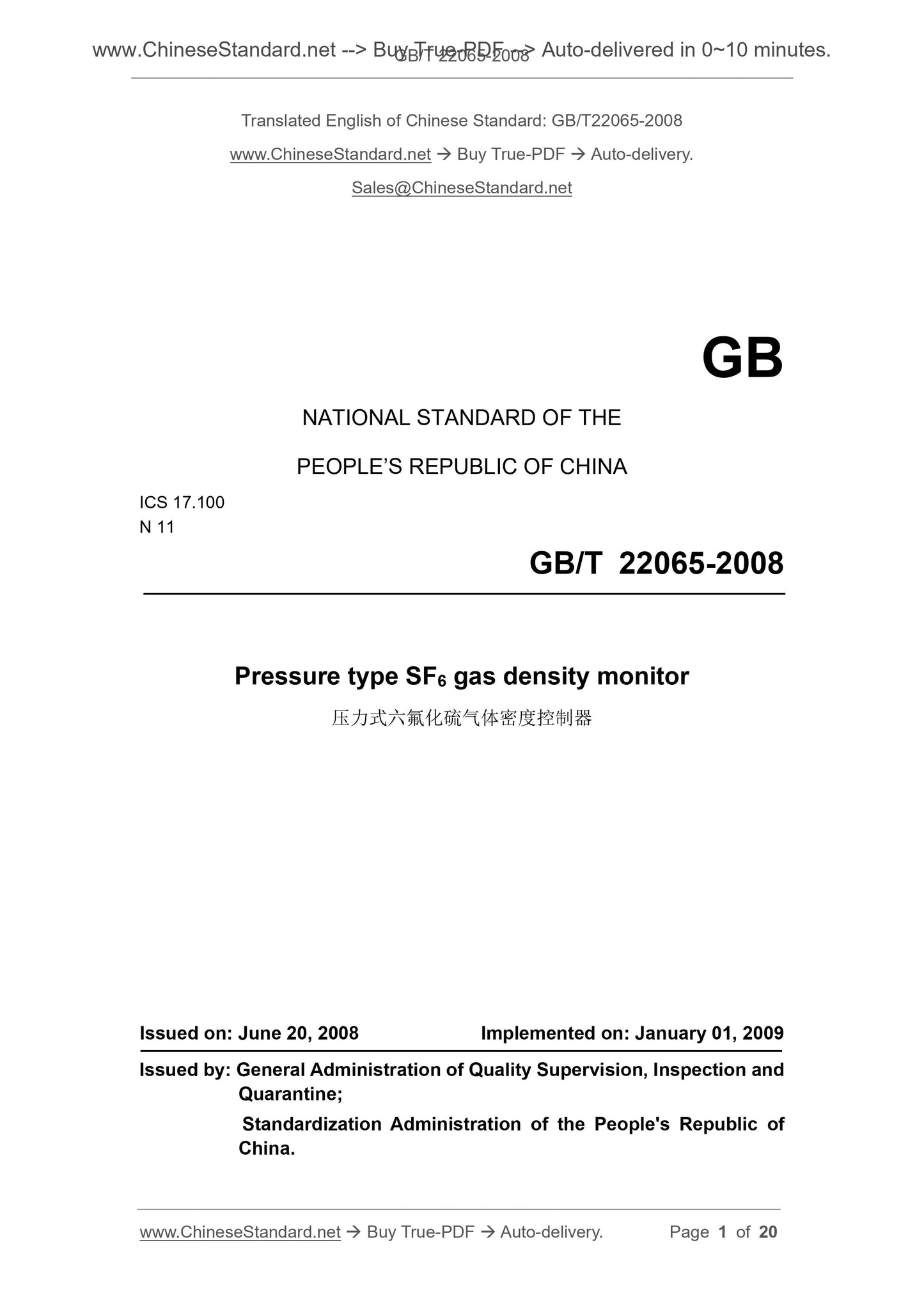
GB/T 22065-2008: Pressure type SF6 gas density monitor
GB/T 22065-2008
GB
NATIONAL STANDARD OF THE
PEOPLE’S REPUBLIC OF CHINA
ICS 17.100
N 11
Pressure type SF6 gas density monitor
压力式六氟化硫气体密度控制器
ISSUED ON. JUNE 20, 2008
IMPLEMENTED ON. JANUARY 01, 2009
Issued by. General Administration of Quality Supervision, Inspection and
Quarantine;
Standardization Administration of the People's Republic of
China.
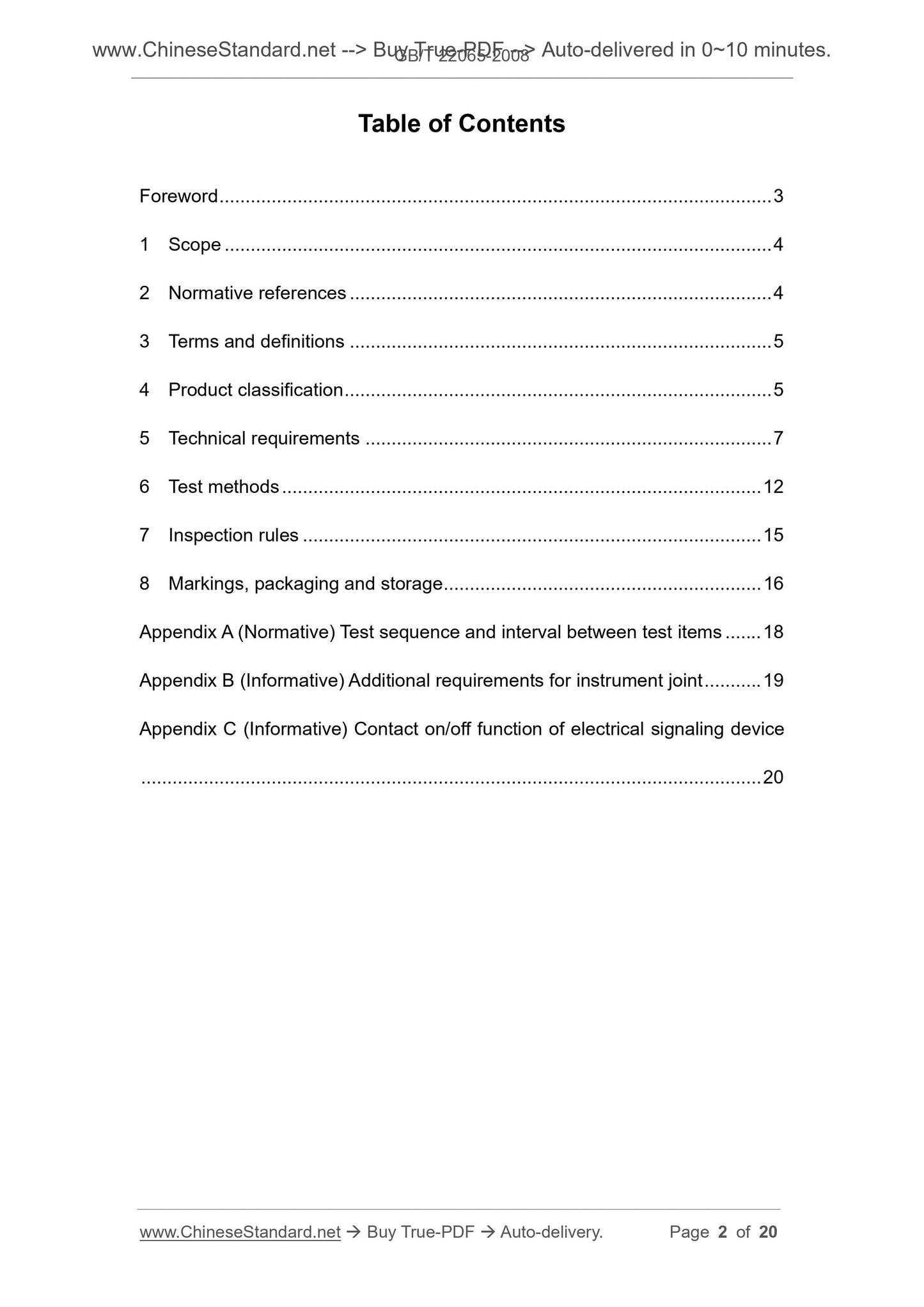
Table of Contents
Foreword ... 3
1 Scope ... 4
2 Normative references ... 4
3 Terms and definitions ... 5
4 Product classification ... 5
5 Technical requirements ... 7
6 Test methods ... 12
7 Inspection rules ... 15
8 Markings, packaging and storage ... 16
Appendix A (Normative) Test sequence and interval between test items ... 18
Appendix B (Informative) Additional requirements for instrument joint ... 19
Appendix C (Informative) Contact on/off function of electrical signaling device
... 20
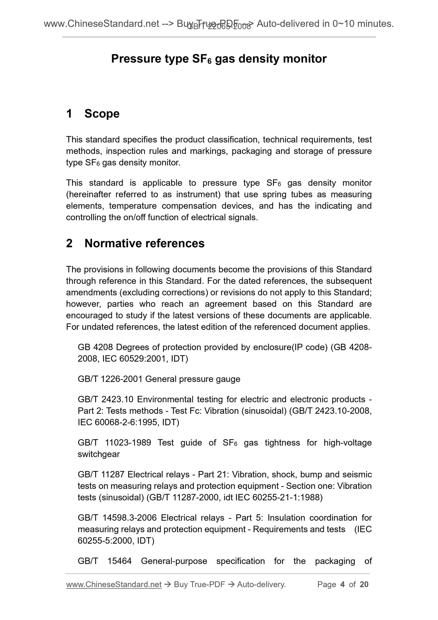
Pressure type SF6 gas density monitor
1 Scope
This standard specifies the product classification, technical requirements, test
methods, inspection rules and markings, packaging and storage of pressure
type SF6 gas density monitor.
This standard is applicable to pressure type SF6 gas density monitor
(hereinafter referred to as instrument) that use spring tubes as measuring
elements, temperature compensation devices, and has the indicating and
controlling the on/off function of electrical signals.
2 Normative references
The provisions in following documents become the provisions of this Standard
through reference in this Standard. For the dated references, the subsequent
amendments (excluding corrections) or revisions do not apply to this Standard;
however, parties who reach an agreement based on this Standard are
encouraged to study if the latest versions of these documents are applicable.
For undated references, the latest edition of the referenced document applies.
GB 4208 Degrees of protection provided by enclosure(IP code) (GB 4208-
2008, IEC 60529.2001, IDT)
GB/T 1226-2001 General pressure gauge
GB/T 2423.10 Environmental testing for electric and electronic products -
Part 2. Tests methods - Test Fc. Vibration (sinusoidal) (GB/T 2423.10-2008,
IEC 60068-2-6.1995, IDT)
GB/T 11023-1989 Test guide of SF6 gas tightness for high-voltage
switchgear
GB/T 11287 Electrical relays - Part 21. Vibration, shock, bump and seismic
tests on measuring relays and protection equipment - Section one. Vibration
tests (sinusoidal) (GB/T 11287-2000, idt IEC 60255-21-1.1988)
GB/T 14598.3-2006 Electrical relays - Part 5. Insulation coordination for
measuring relays and protection equipment - Requirements and tests (IEC
60255-5.2000, IDT)
GB/T 15464 General-purpose specification for the packaging of
instrumentation products
JB/T 5528 Scale and distribution for pressure gauge
JB/T 9329 Basic environmental conditions and testing methods for
instruments transportation and storage in the transportation
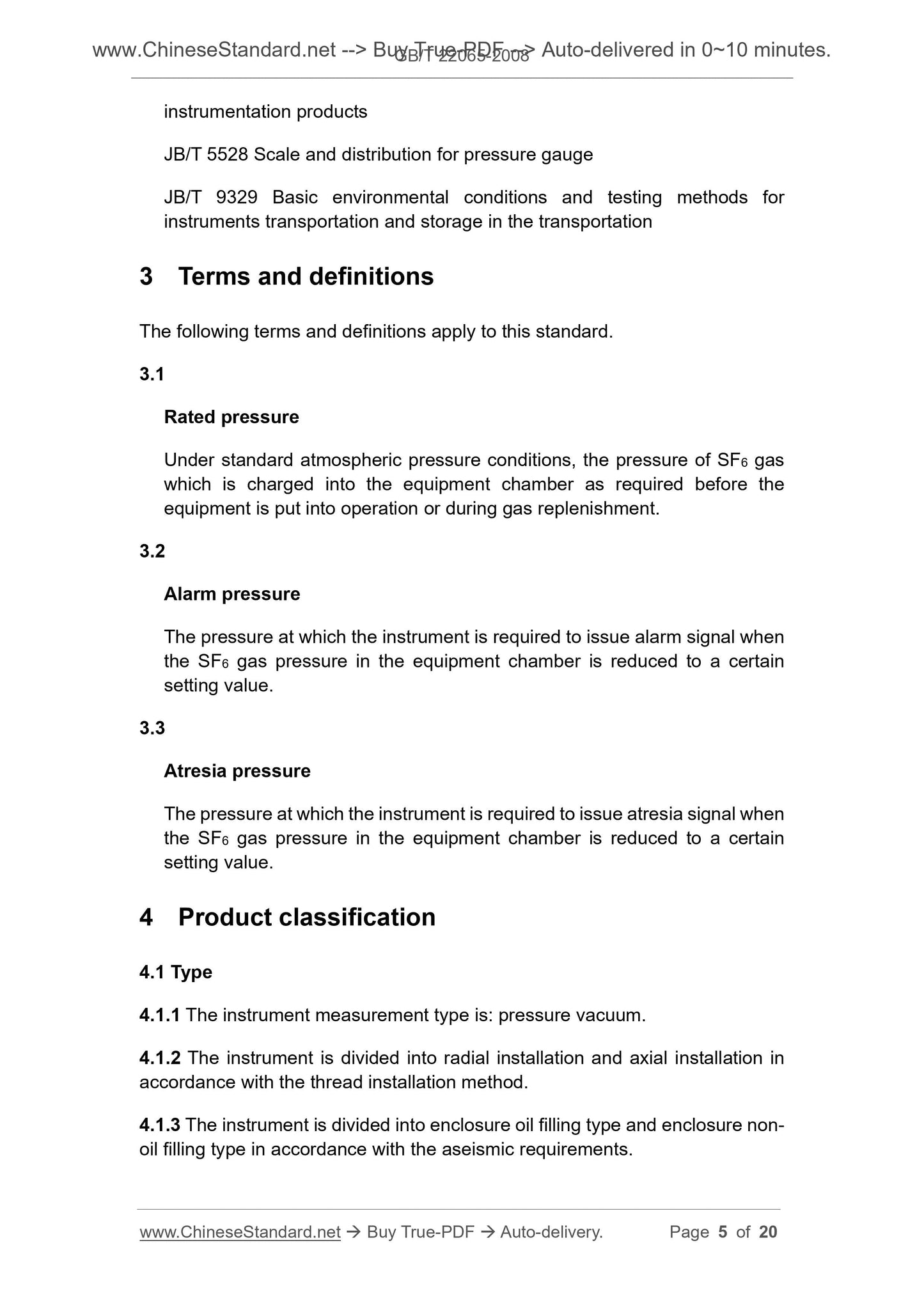
3 Terms and definitions
The following terms and definitions apply to this standard.
3.1
Rated pressure
Under standard atmospheric pressure conditions, the pressure of SF6 gas
which is charged into the equipment chamber as required before the
equipment is put into operation or during gas replenishment.
3.2
Alarm pressure
The pressure at which the instrument is required to issue alarm signal when
the SF6 gas pressure in the equipment chamber is reduced to a certain
setting value.
3.3
Atresia pressure
The pressure at which the instrument is required to issue atresia signal when
the SF6 gas pressure in the equipment chamber is reduced to a certain
setting value.
4 Product classification
4.1 Type
4.1.1 The instrument measurement type is. pressure vacuum.
4.1.2 The instrument is divided into radial installation and axial installation in
accordance with the thread installation method.
4.1.3 The instrument is divided into enclosure oil filling type and enclosure non-
oil filling type in accordance with the aseismic requirements.
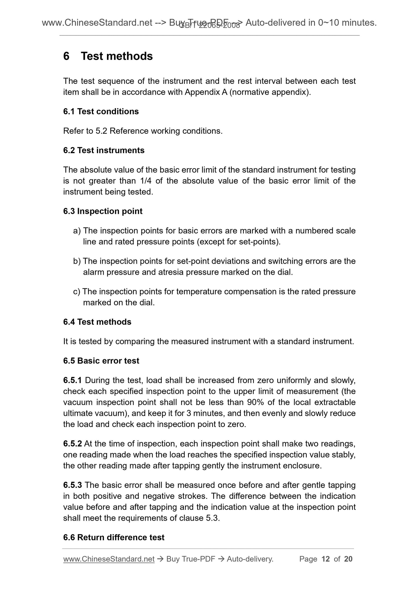
6 Test methods
The test sequence of the instrument and the rest interval between each test
item shall be in accordance with Appendix A (normative appendix).
6.1 Test conditions
Refer to 5.2 Reference working conditions.
6.2 Test instruments
The absolute value of the basic error limit of the standard instrument for testing
is not greater than 1/4 of the absolute value of the basic error limit of the
instrument being tested.
6.3 Inspection point
a) The inspection points for basic errors are marked with a numbered scale
line and rated pressure points (except for set-points).
b) The inspection points for set-point deviations and switching errors are the
alarm pressure and atresia pressure marked on the dial.
c) The inspection points for temperature compensation is the rated pressure
marked on the dial.
6.4 Test methods
It is tested by comparing the measured instrument with a standard instrument.
6.5 Basic error test
6.5.1 During the test, load shall be increased from zero uniformly and slowly,
check each specified inspection point to the upper limit of measurement (the
vacuum inspection point shall not be less than 90% of the local extractable
ultimate vacuum), and keep it for 3 minutes, and then evenly and slowly reduce
the load and check each inspection point to zero.
6.5.2 At the time of inspection, each inspection point shall make two readings,
one reading made when the load reaches the specified inspection value stably,
the other reading made after tapping gently the instrument enclosure.
6.5.3 The basic error shall be measured once before and after gentle tapping
in both positive and negative strokes. The difference between the indication
value before and after tapping and the indication value at the inspection point
shall meet the requirements of clause 5.3.
6.6 Return difference test
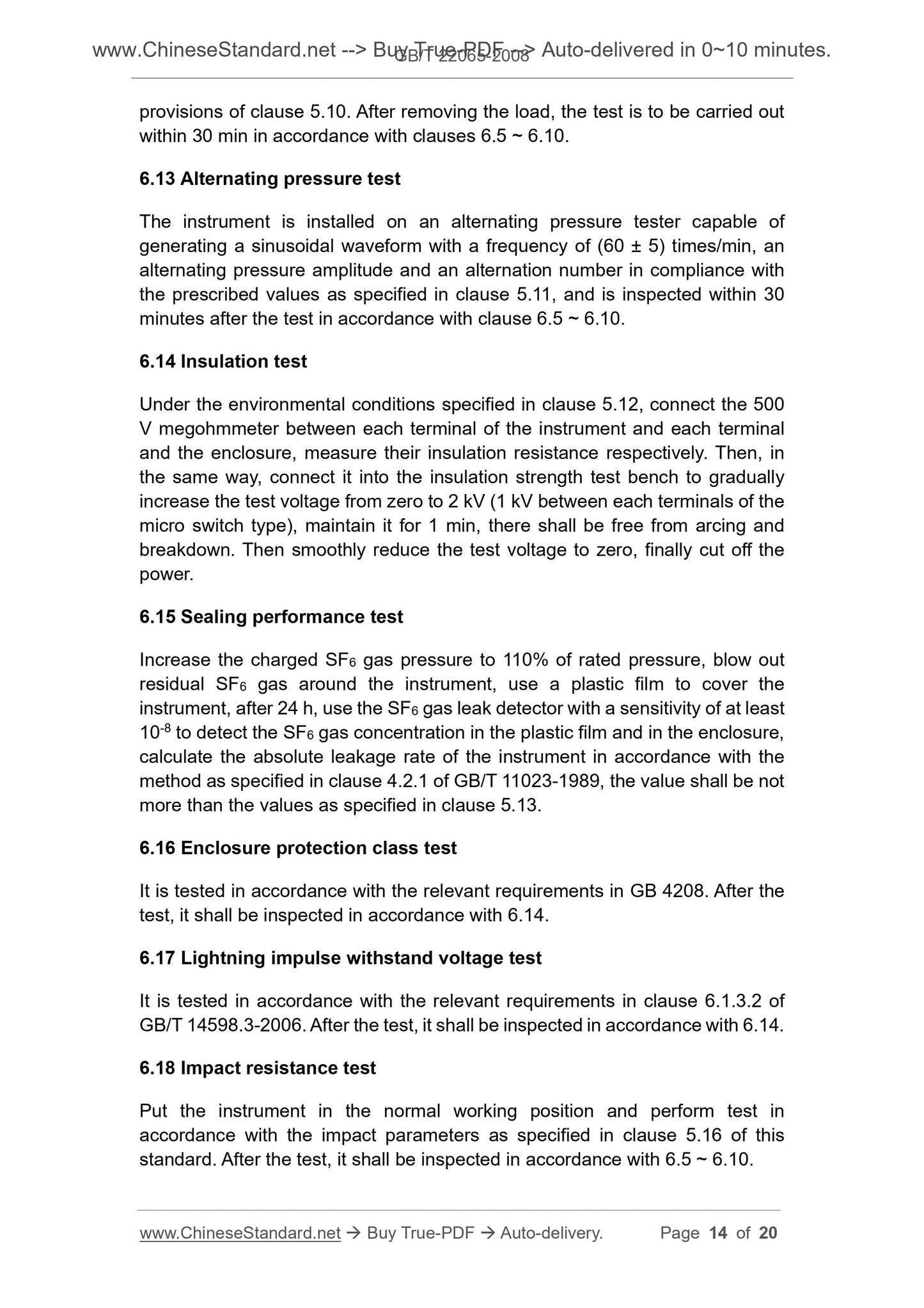
provisions of clause 5.10. After removing the load, the test is to be carried out
within 30 min in accordance with clauses 6.5 ~ 6.10.
6.13 Alternating pressure test
The instrument is installed on an alternating pressure tester capable of
generating a sinusoidal waveform with a frequency of (60 ± 5) times/min, an
alternating pressure amplitude and an alternation number in compliance with
the prescribed values as specified in clause 5.11, and is inspected within 30
minutes after the test in accordance with clause 6.5 ~ 6.10.
6.14 Insulation test
Under the environmental conditions specified in clause 5.12, connect the 500
V megohmmeter between each terminal of the instrument and each terminal
and the enclosure, measure their insulation resistance respectively. Then, in
the same way, connect it into the insulation strength test bench to gradually
increase the test voltage from zero to 2 kV (1 kV between each terminals of the
micro switch type), maintain it for 1 min, there shall be free from arcing and
breakdown. Then smoothly reduce the test voltage to zero, finally cut off the
power.
6.15 Sealing performance test
Increase the charged SF6 gas pressure to 110% of rated pressure, blow out
residual SF6 gas around the instrument, use a plastic film to cover the
instrument, after 24 h, use the SF6 gas leak detector with a sensitivity of at least
10-8 to detect the SF6 gas concentration in the plastic film and in the enclosure,
calculate the absolute leakage rate of the instrument in accordance with the
method as specified in clause 4.2.1 of GB/T ...
Share
