1
/
of
8
www.ChineseStandard.us -- Field Test Asia Pte. Ltd.
GB/T 230.2-2022 English PDF (GB/T230.2-2022)
GB/T 230.2-2022 English PDF (GB/T230.2-2022)
Regular price
$380.00
Regular price
Sale price
$380.00
Unit price
/
per
Shipping calculated at checkout.
Couldn't load pickup availability
GB/T 230.2-2022: Metallic materials - Rockwell hardness test - Part 2: Verification and calibration of testing machines and indenters
Delivery: 9 seconds. Download (& Email) true-PDF + Invoice.
Get Quotation: Click GB/T 230.2-2022 (Self-service in 1-minute)
Historical versions (Master-website): GB/T 230.2-2022
Preview True-PDF (Reload/Scroll-down if blank)
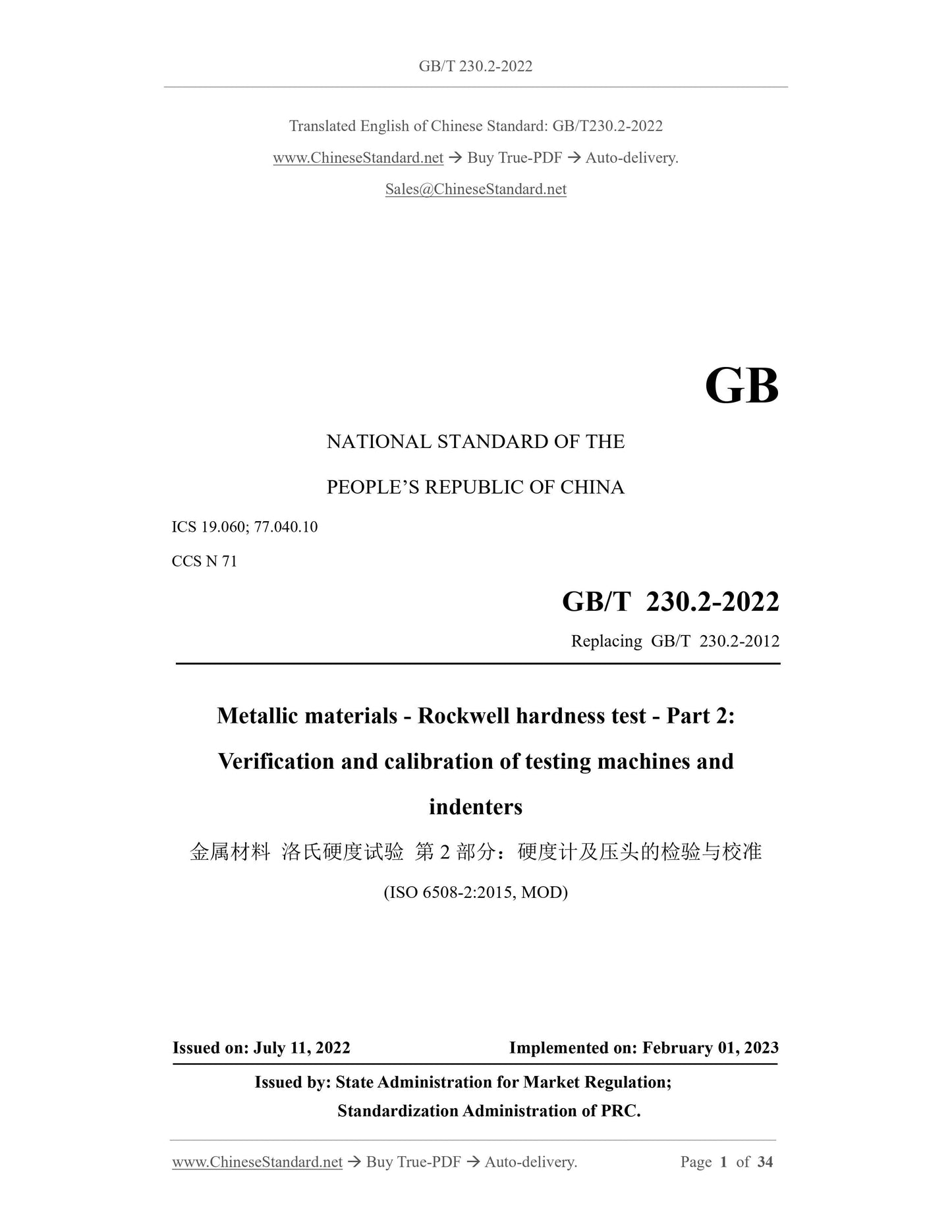
GB/T 230.2-2022
GB
NATIONAL STANDARD OF THE
PEOPLE’S REPUBLIC OF CHINA
ICS 19.060; 77.040.10
CCS N 71
Replacing GB/T 230.2-2012
Metallic materials - Rockwell hardness test - Part 2:
Verification and calibration of testing machines and
indenters
(ISO 6508-2:2015, MOD)
ISSUED ON: JULY 11, 2022
IMPLEMENTED ON: FEBRUARY 01, 2023
Issued by: State Administration for Market Regulation;
Standardization Administration of PRC.
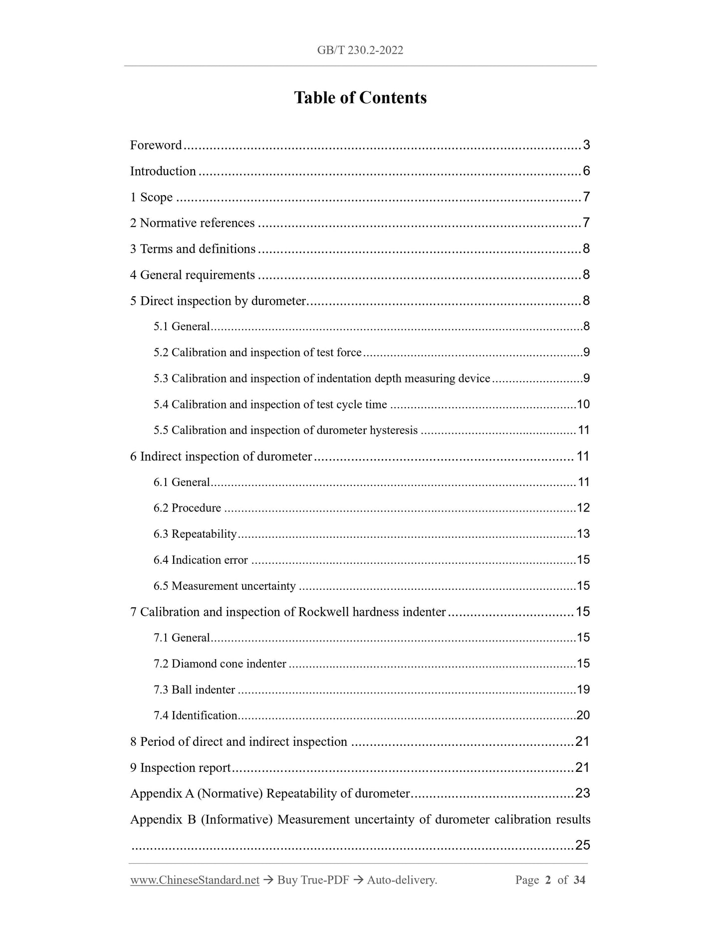
Table of Contents
Foreword ... 3
Introduction ... 6
1 Scope ... 7
2 Normative references ... 7
3 Terms and definitions ... 8
4 General requirements ... 8
5 Direct inspection by durometer ... 8
5.1 General... 8
5.2 Calibration and inspection of test force ... 9
5.3 Calibration and inspection of indentation depth measuring device ... 9
5.4 Calibration and inspection of test cycle time ... 10
5.5 Calibration and inspection of durometer hysteresis ... 11
6 Indirect inspection of durometer ... 11
6.1 General... 11
6.2 Procedure ... 12
6.3 Repeatability ... 13
6.4 Indication error ... 15
6.5 Measurement uncertainty ... 15
7 Calibration and inspection of Rockwell hardness indenter ... 15
7.1 General... 15
7.2 Diamond cone indenter ... 15
7.3 Ball indenter ... 19
7.4 Identification ... 20
8 Period of direct and indirect inspection ... 21
9 Inspection report ... 21
Appendix A (Normative) Repeatability of durometer ... 23
Appendix B (Informative) Measurement uncertainty of durometer calibration results
... 25
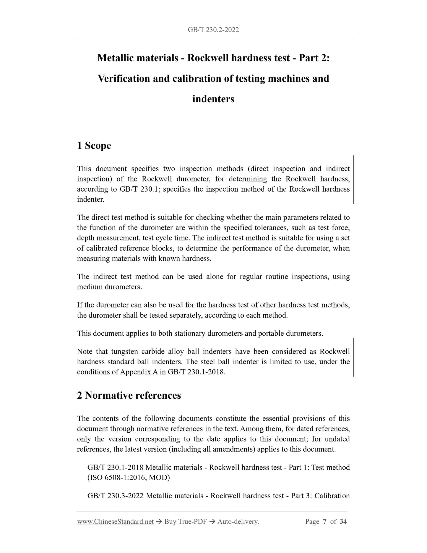
Metallic materials - Rockwell hardness test - Part 2:
Verification and calibration of testing machines and
indenters
1 Scope
This document specifies two inspection methods (direct inspection and indirect
inspection) of the Rockwell durometer, for determining the Rockwell hardness,
according to GB/T 230.1; specifies the inspection method of the Rockwell hardness
indenter.
The direct test method is suitable for checking whether the main parameters related to
the function of the durometer are within the specified tolerances, such as test force,
depth measurement, test cycle time. The indirect test method is suitable for using a set
of calibrated reference blocks, to determine the performance of the durometer, when
measuring materials with known hardness.
The indirect test method can be used alone for regular routine inspections, using
medium durometers.
If the durometer can also be used for the hardness test of other hardness test methods,
the durometer shall be tested separately, according to each method.
This document applies to both stationary durometers and portable durometers.
Note that tungsten carbide alloy ball indenters have been considered as Rockwell
hardness standard ball indenters. The steel ball indenter is limited to use, under the
conditions of Appendix A in GB/T 230.1-2018.
2 Normative references
The contents of the following documents constitute the essential provisions of this
document through normative references in the text. Among them, for dated references,
only the version corresponding to the date applies to this document; for undated
references, the latest version (including all amendments) applies to this document.
GB/T 230.1-2018 Metallic materials - Rockwell hardness test - Part 1: Test method
(ISO 6508-1:2016, MOD)
GB/T 230.3-2022 Metallic materials - Rockwell hardness test - Part 3: Calibration
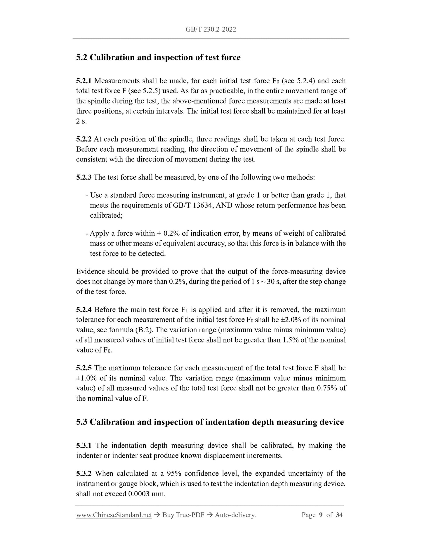
5.2 Calibration and inspection of test force
5.2.1 Measurements shall be made, for each initial test force F0 (see 5.2.4) and each
total test force F (see 5.2.5) used. As far as practicable, in the entire movement range of
the spindle during the test, the above-mentioned force measurements are made at least
three positions, at certain intervals. The initial test force shall be maintained for at least
2 s.
5.2.2 At each position of the spindle, three readings shall be taken at each test force.
Before each measurement reading, the direction of movement of the spindle shall be
consistent with the direction of movement during the test.
5.2.3 The test force shall be measured, by one of the following two methods:
- Use a standard force measuring instrument, at grade 1 or better than grade 1, that
meets the requirements of GB/T 13634, AND whose return performance has been
calibrated;
- Apply a force within ± 0.2% of indication error, by means of weight of calibrated
mass or other means of equivalent accuracy, so that this force is in balance with the
test force to be detected.
Evidence should be provided to prove that the output of the force-measuring device
does not change by more than 0.2%, during the period of 1 s ~ 30 s, after the step change
of the test force.
5.2.4 Before the main test force F1 is applied and after it is removed, the maximum
tolerance for each measurement of the initial test force F0 shall be ±2.0% of its nominal
value, see formula (B.2). The variation range (maximum value minus minimum value)
of all measured values of initial test force shall not be greater than 1.5% of the nominal
value of F0.
5.2.5 The maximum tolerance for each measurement of the total test force F shall be
±1.0% of its nominal value. The variation range (maximum value minus minimum
value) of all measured values of the total test force shall not be greater than 0.75% of
the nominal value of F.
5.3 Calibration and inspection of indentation depth measuring device
5.3.1 The indentation depth measuring device shall be calibrated, by making the
indenter or indenter seat produce known displacement increments.
5.3.2 When calculated at a 95% confidence level, the expanded uncertainty of the
instrument or gauge block, which is used to test the indentation depth measuring device,
shall not exceed 0.0003 mm.
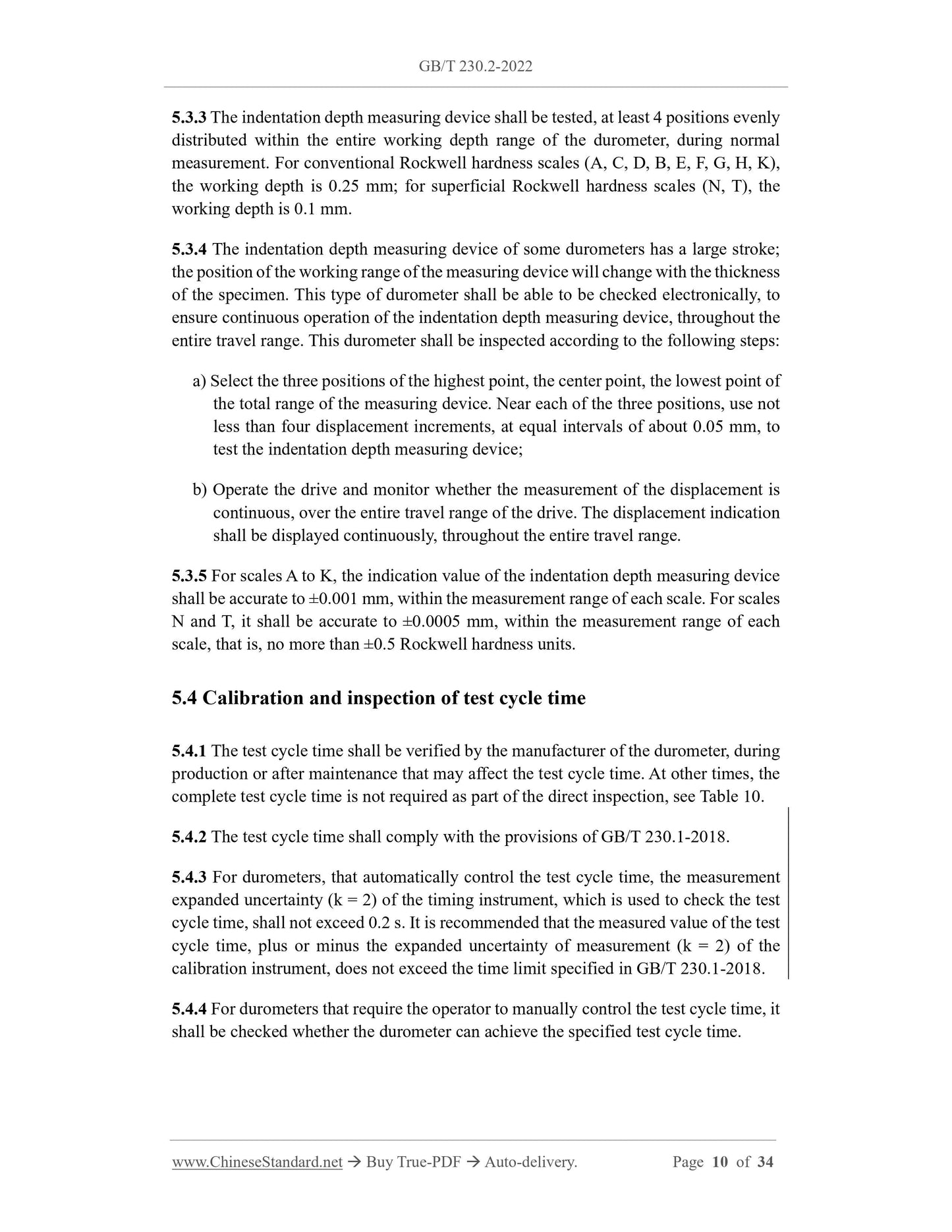
5.3.3 The indentation depth measuring device shall be tested, at least 4 positions evenly
distributed within the entire working depth range of the durometer, during normal
measurement. For conventional Rockwell hardness scales (A, C, D, B, E, F, G, H, K),
the working depth is 0.25 mm; for superficial Rockwell hardness scales (N, T), the
working depth is 0.1 mm.
5.3.4 The indentation depth measuring device of some durometers has a large stroke;
the position of the working range of the measuring device will change with the thickness
of the specimen. This type of durometer shall be able to be checked electronically, to
ensure continuous operation of the indentation depth measuring device, throughout the
entire travel range. This durometer shall be inspected according to the following steps:
a) Select the three positions of the highest point, the center point, the lowest point of
the total range of the measuring device. Near each of the three positions, use not
less than four displacement increments, at equal intervals of about 0.05 mm, to
test the indentation depth measuring device;
b) Operate the drive and monitor whether the measurement of the displacement is
continuous, over the entire travel range of the drive. The displacement indication
shall be displayed continuously, throughout the entire travel range.
5.3.5 For scales A to K, the indication value of the indentation depth measuring device
shall be accurate to ±0.001 mm, within the measurement range of each scale. For scales
N and T, it shall be accurate to ±0.0005 mm, within the measurement range of each
scale, that is, no more than ±0.5 Rockwell hardness units.
5.4 Calibration and inspection of test cycle time
5.4.1 The test cycle time shall be verified by the manufacturer of the durometer, during
production or after maintenance that may affect the test cycle time. At other times, the
complete test cycle time is not required as part of the direct inspection, see Table 10.
5.4.2 The test cycle time shall comply with the provisions of GB/T 230.1-2018.
5.4.3 For durometers, that automatically control the test cycle time, the measurement
expanded uncertainty (k = 2) of the timing instrument, which is used to check the test
cycle time, shall not exceed 0.2 s. It is recommended that the measured value of the test
cycle time, plus or minus the expanded uncertainty of measurement (k = 2) of the
calibration instrument, does not exceed the time limit specified in GB/T 230.1-2018.
5.4.4 For durometers that require the operator to manually control the test cycle time, it
shall be checked whether the durometer can achieve the specified test cycle time.
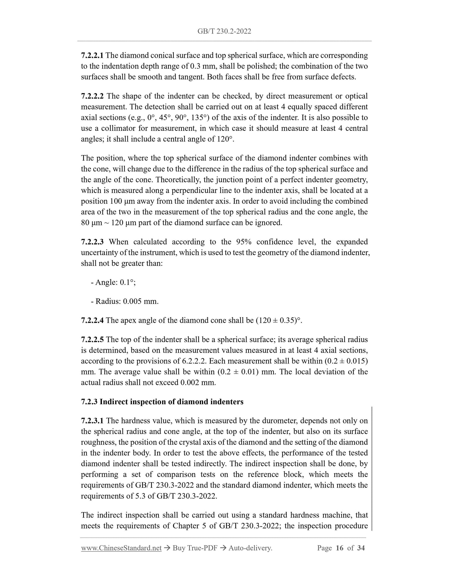
7.2.2.1 The diamond conical surface and top spherical surface, which are corresponding
to the indentation depth range of 0.3 mm, shall be polished; the combination of the two
surfaces shall be smooth and tangent. Both faces shall be free from surface defects.
7.2.2.2 The shape of the indenter can be checked, by direct measurement or optical
measurement. The detection shall be carried out on at least 4 equally spaced different
axial sections (e.g., 0°, 45°, 90°, 135°) of the axis of the indenter. It is also possible to
use a collimator for measurement, in which case it should measure at least 4 central
angles; it shall include a central angle of 120°.
The position, where the top spherical surface of the diamond indenter combines with
the cone, will change due to the difference in the radius of the top spherical surface and
the angle of the cone. Theoretically, the junction point of a perfect indenter geometry,
which is measured along a perpendicular line to the indenter axis, shall be located at a
position 100 μm away from the indenter axis. In order to avoid including the combined
area of the two in the measurement of the top spherical radius and the cone angle, the
80 μm ~ 120 μm part of the diamond surface can be ignored.
7.2.2.3 When calculated according to the 95% confidence level, the expanded
uncertainty of the instrument, which is used to test the geometry of the diamond indenter,
shall not be greater than:
- Angle: 0.1°;
- Radius: 0.005 mm.
7.2.2.4 The apex angle of the diamond cone shall be (120 ± 0.35)°.
7.2.2.5 The top of the indenter shall be a spherical surface; its average spherical radius
is determined, based on the measurement values measured in at least 4 axial sections,
according to the provisions of 6.2.2.2. Each measurement shall be within (0.2 ± 0.015)
mm. The average value shall be within (0.2 ± 0.01) mm. The local deviation of the
actual radius shall not exceed 0.002 mm.
7.2.3 Indirect inspection of diamond indenters
7.2.3.1 The hardness value, which is measured by the durometer, depends not only on
the spherical radius and cone angle, at the top of the indenter, but also on its surface
roughness, the position of the crystal axis of the diamond and the setting of the diamond
in the indenter body. In order to test the above effects, the performance of the tested
diamond indenter shall be tested indirectly. The indirect inspection shall be done, by
performing a set of comparison tests on the reference block, which meets the
requirements of GB/T 230.3-2022 and the standard diamond indenter, which meets the
requirements of 5.3 of GB/T 230.3-2022.
The indirect inspection shall be carried out using a standard hardness machine, that
meets the requirements of Chapter 5 of GB/T 230.3-2022; the inspection procedure
Appendix B
(Informative)
Measurement uncertainty of durometer calibration results
B.1 Overview
Measurement uncertainty analysis is a powerful tool for identifying sources of error and
understanding differences in measurement results. This Appendix gives guidance on the
assessment of uncertainty. If the customer has no special requirements, this method can
be used as a reference. The guidelines, which are presented in this document, for the
performance of durometers have been developed and refined over a considerable period
of time. When the determination of the durometer needs to meet a specified tolerance,
the tolerance already includes the uncertainty related to the measuring instrument and
(or) reference standard used. Therefore, any further adjustments to the uncertainty (such
as reduction of tolerances by measurement uncertainty) are not appropriate. This applies
to all measurements, which are made on the durometer, either directly or indirectly. In
various cases, these values may be simple measurements, which are taken by specified
measuring instruments and/or reference standards used, when assessing compliance of
a durometer with the provisions of this document. However, in some special cases, it is
also permissible to reduce the tolerance by measurement uncertainty. This situation only
applies where the relevant parties reach an agreement by consensus.
B.2 Direct inspection - Uncertainty of measurement of test parts of a durometer
B.2.1 Uncertainty of test force calibration
Measure the test force directly. Calculate and report the difference -- BETWEEN the
measured value of each force applied by the durometer AND the corresponding
standard force value indicated by the standard force gauge. A direct inspection checks
that each value is within the specified limits of the maximum allowable error. Therefore,
a method of measuring uncertainty using the calculated value of the true value of the
test force, which is specified in the relevant test method, is given below. The relative
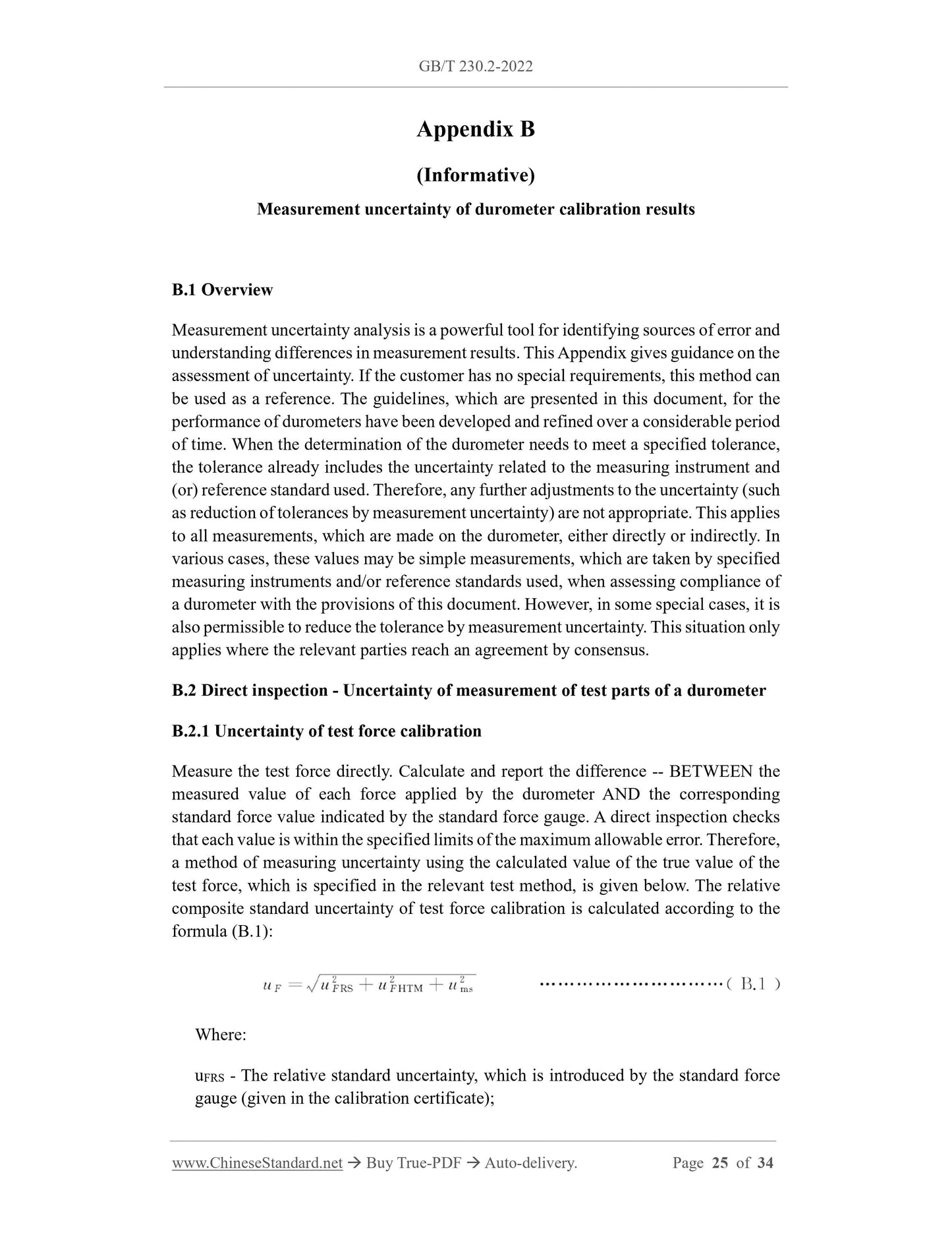
composite standard uncertainty of test force calibration is calculated according to the
formula (B.1):
Where:
uFRS - The relative standard uncertainty, which is introduced by the standard force
gauge (given in the calibration certificate);
B.3 Indirect inspection - Uncertainty in durometer calibration
B.3.1 Uncertainty of durometer error
Note: In this Appendix, according to the definition of the hardness test standard, the subscript
"CRM (Certified Reference Material)" means "reference block".
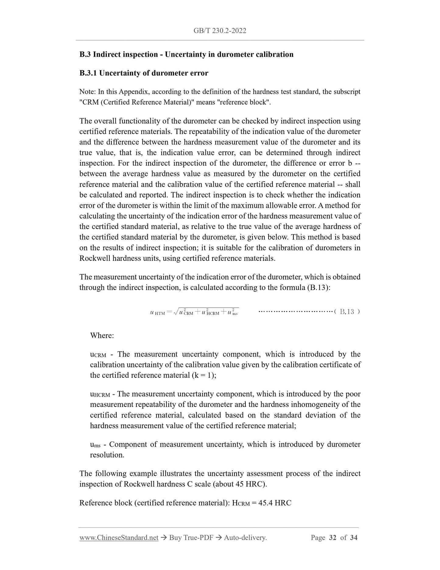
The overall functionality of the durometer can be checked by indirect inspection using
certified reference materials. The repeatability of the indication value of the durometer
and the difference between the hardness measurement value of the durometer and its
true value, that is, the indication value error, can be determined through indirect
inspection. For th...
Share
