1
/
of
12
www.ChineseStandard.us -- Field Test Asia Pte. Ltd.
GB/T 23341.2-2018 English PDF (GB/T23341.2-2018)
GB/T 23341.2-2018 English PDF (GB/T23341.2-2018)
Regular price
$325.00
Regular price
Sale price
$325.00
Unit price
/
per
Shipping calculated at checkout.
Couldn't load pickup availability
GB/T 23341.2-2018: Turbochargers - Part 2: Test methods
Delivery: 9 seconds. Download (& Email) true-PDF + Invoice.
Get Quotation: Click GB/T 23341.2-2018 (Self-service in 1-minute)
Historical versions (Master-website): GB/T 23341.2-2018
Preview True-PDF (Reload/Scroll-down if blank)
GB/T 23341.2-2018
NATIONAL STANDARD OF THE
PEOPLE’S REPUBLIC OF CHINA
ICS 27.020
J 91
Replacing GB/T 23341.2-2009
Turbochargers - Part 2: Test methods
ISSUED ON: FEBRUARY 06, 2018
IMPLEMENTED ON: SEPTEMBER 01, 2018
Issued by: General Administration of Quality Supervision, Inspection and
Quarantine;
Standardization Administration of the People's Republic of China.
Table of Contents
Foreword ... 3
1 Scope ... 5
2 Normative references ... 5
3 Terms and definitions ... 5
4 Technical requirements for test equipment ... 6
5 General conditions for tests ... 8
6 Test items and methods ... 8
Annex A (informative) Record sheet for compressor performance test ... 28
Annex B (informative) Record sheet for turbine performance test ... 30
Annex C (informative) Record sheet for supercharger self cycle test ... 31
Annex D (informative) Schematic diagram of turbine casing flow capacity test ... 33
Turbochargers - Part 2: Test methods
1 Scope
This Part of GB/T 23341 specifies technical requirements for test equipment of radial
and mixed-flow turbochargers (hereinafter referred to as "the supercharger") and
general methods for bench performance test.
This Part applies to superchargers for internal combustion engines (including diesel
engines, gasoline engines and natural gas engines) for vehicles, ships, construction
machinery, agricultural and forestry machinery, power generation and other purposes.
This Part does not apply to axial-flow superchargers.
2 Normative references
The following referenced documents are indispensable for the application of this
document. For dated references, only the edition cited applies. For undated references,
the latest edition of the referenced document (including any amendments) applies.
GB/T 2624 (all parts), Full differential pressure device installed in a pipe of circular
cross-section measuring fluid flow
GB/T 23341.1-2018, Turbochargers - Part 1: General requirements
JB/T 6002-2007, Turbochargers. Limit values and measurement methods for
cleanliness
JB/T 9752.3, Turbochargers - Part 3: Balance quality requirements and check
methods of rotors
JB/T 12334-2015, Measuring method for noise of turbochargers
JB/T 12335-2015, Turbochargers. Leakage test method
3 Terms and definitions
For the purposes of this document, the terms and definitions defined in GB/T 23341.1
as well as the followings apply.
3.1 hot blast test
The test that the external source compressed air is heated and input to the turbine, and
the flow, such as the non-contact electromagnetic sensor tube speed measurement or
photoelectric speed measurement instrument for the magnetization of the compressor
impeller lock nut. Instrument accuracy is ±0.2% of full scale.
4.3 Pressure measurement
4.3.1 Static pressure measurement of compressor or turbine inlet and outlet gas. Use a
measuring tube with a straight and smooth inner wall and a circular section. The area
of the pipeline is not less than the area of the connected inlet and outlet. The pipe length
is not less than 5 times the pipe diameter. The length of the straight section before the
static pressure measuring point (in the direction of the airflow) is not less than 2 times
the pipe diameter. In addition to the direct measurement of the total pressure of the gas
at the inlet and outlet, it can also be calculated from the measured static pressure, total
temperature and flow rate. Instrument accuracy is ±0.2% of full scale.
4.3.2 Lubricating oil pressure measurement. Instrument accuracy is ±2% of full scale.
4.3.3 Ambient barometric pressure measurement. Instrument accuracy is ±2% of full
scale.
4.4 Temperature measurement
4.4.1 Compressor and turbine inlet and outlet temperatures shall be measured in circular
section measuring tubes by electrical thermometers with stagnant sheaths. The
measuring point shall be arranged at a position of 0.5 times the pipe diameter behind
the static pressure measuring point (in the direction of the airflow). It shall be staggered
from the pressure measuring point. The electrical thermometer shall be inserted
vertically. The depth is 1/3 of the diameter of the measuring pipe (calculated by the
position of the orifice of the stagnant sheath). When the diameter of the measuring pipe
is small and cannot be inserted into the depth specified by the thermometer itself, it is
allowed to insert the 1/2 position of the diameter of the measuring pipe.
4.4.2 When measuring the performance of the compressor, the accuracy of the
instrument is ±0.3% of the full scale. When measuring turbine performance, the
instrument accuracy is ±0.5% of full scale. For other measurement of turbine inlet and
outlet temperature, the instrument accuracy is ±1% of full scale.
4.4.3 Lubricating oil temperature measurement. Instrument accuracy is ±2% of full
scale.
4.4.4 Ambient air temperature measurement. Instrument accuracy is ±1% of full scale.
4.5 Flow measurement
Compressor flow measurement can be carried out by gas mass flowmeter or standard
orifice flowmeter or end-face intake double-wire flowmeter. The standard orifice
flowmeter is installed on the compressor outlet piping. The end-face intake double-wire
flowmeter is installed on the compressor inlet piping. Turbine flow measurement can
be carried out by gas mass flowmeter or standard orifice flowmeter. The flow meter is
mounted on the intake duct in front of the combustion chamber. The design,
manufacture, installation, use and flow calculation of standard orifice flowmeter shall
comply with the provisions of GB/T 2624. The end-face air inlet double-wire flowmeter
or other types of flowmeters shall be calibrated before they can be used. Instrument
accuracy is ±0.5% of full scale.
5 General conditions for tests
5.1 The supercharger used for the test shall meet the requirements of the product
technical documents and pass the inspection.
5.2 The measuring instrument used for the test shall be verified and calibrated by an
authorized metrology department. It shall be accompanied by a certificate. It shall be
within the validity period of the verification period.
5.3 The supercharger for diesel engine shall use at least CD40 or lubricating oil of
equivalent level. Gasoline engine and natural gas supercharger shall use at least
SL15W-40 or lubricating oil of equivalent level.
5.4 During the test, unless otherwise specified, the following parameters shall be
controlled:
a) The lubricating oil inlet oil pressure is 0.25MPa~0.5MPa. The inlet oil
temperature is 60℃~100℃. The outlet oil temperature is ≤120℃.
b) The compressor inlet pressure ≥-6kPa.
c) The turbine outlet back pressure is generally ≤3kPa (for models requiring high
back pressure, it is implemented according to special technical conditions). When
the test pipeline is allowed to have exhaust air, the negative pressure at the turbine
outlet is generally ≤1kPa. However, the ambient conditions shall be kept consistent
throughout the test process, so as to avoid measurement errors. When conducting
the turbine performance test, it is not allowed to use the exhaust air extraction
device. The back pressure of the turbine outlet is ≤600Pa.
d) The cooling water inlet temperature is 75℃~85℃. The cooling water inlet
pressure is 0.1MPa~0.2MPa.
e) The test speed deviation shall be controlled within ±0.5% speed range.
6 Test items and methods
6.1 Compressor performance test
provisions of Chapter 4 and Chapter 5.
6.2.2 Test methods
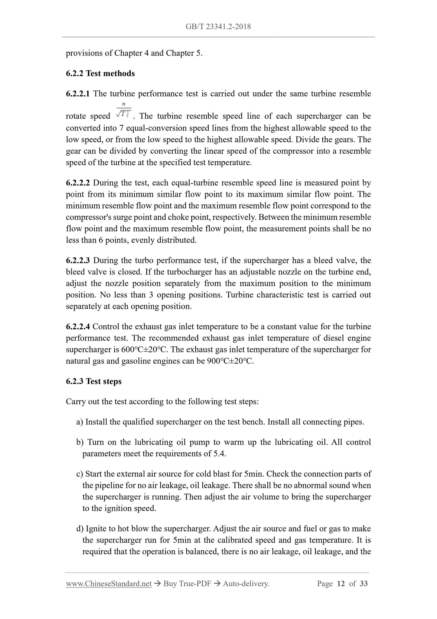
6.2.2.1 The turbine performance test is carried out under the same turbine resemble
rotate speed . The turbine resemble speed line of each supercharger can be
converted into 7 equal-conversion speed lines from the highest allowable speed to the
low speed, or from the low speed to the highest allowable speed. Divide the gears. The
gear can be divided by converting the linear speed of the compressor into a resemble
speed of the turbine at the specified test temperature.
6.2.2.2 During the test, each equal-turbine resemble speed line is measured point by
point from its minimum similar flow point to its maximum similar flow point. The
minimum resemble flow point and the maximum resemble flow point correspond to the
compressor's surge point and choke point, respectively. Between the minimum resemble
flow point and the maximum resemble flow point, the measurement points shall be no
less than 6 points, evenly distributed.
6.2.2.3 During the turbo performance test, if the supercharger has a bleed valve, the
bleed valve is closed. If the turbocharger has an adjustable nozzle on the turbine end,
adjust the nozzle position separately from the maximum position to the minimum
position. No less than 3 opening positions. Turbine characteristic test is carried out
separately at each opening position.
6.2.2.4 Control the exhaust gas inlet temperature to be a constant value for the turbine
performance test. The recommended exhaust gas inlet temperature of diesel engine
supercharger is 600℃±20℃. The exhaust gas inlet temperature of the supercharger for
natural gas and gasoline engines can be 900℃±20℃.
6.2.3 Test steps
Carry out the test according to the following test steps:
a) Install the qualified supercharger on the test bench. Install all connecting pipes.
b) Turn on the lubricating oil pump to warm up the lubricating oil. All control
parameters meet the requirements of 5.4.
c) Start the external air source for cold blast for 5min. Check the connection parts of
the pipeline for no air leakage, oil leakage. There shall be no abnormal sound when
the supercharger is running. Then adjust the air volume to bring the supercharger
to the ignition speed.
d) Ignite to hot blow the supercharger. Adjust the air source and fuel or gas to make
the supercharger run for 5min at the calibrated speed and gas temperature. It is
required that the operation is balanced, there is no air leakage, oil leakage, and the
sound is normal.
e) Adjust air source and fuel or gas. Control the temperature of the exhaust gas inlet
to a constant value. Select an equal-resemble speed line. Find surge and choke
points. Evenly divide the flow of the two intervals into more than 6 points for
testing. During the test, measure the value of each measuring point after the test
control parameters are adjusted to the specified value and stabilized for 3min (time
can be shorten for the surge point). Measure each point for 5 times. Take the
average value when calculating.
f) After the test, close the fuel or gas valve. Then use a cold air source to blow the
cold supercharger.
6.2.4 Measurement parameters
During the test, measure the following parameters:
a) Total pressure of turbine inlet gas;
b) Total temperature of turbine inlet gas;
c) Turbine flow or flowmeter gas differential pressure;
d) Turbine outlet gas static pressure;
e) Turbine outlet gas static temperature;
f) Total pressure of compressor inlet gas;
g) Total temperature of compressor inlet gas;
h) Total pressure of compressor outlet gas;
i) Total temperature of compressor outlet gas;
j) Supercharger rotate speed;
k) Lubricating oil inlet temperature;
l) Lubricating oil outlet temperature;
m) Lubricating oil flow;
n) Atmospheric pressure and ambient temperature during the test.
6.2.5 Data processing
According to the parameters measured in the test, according to the relevant formulas in
GB/T 23341.1-2018, calculate turbine resemble flow, turbine efficiency, expansion
pressure and speed to prevent over-temperature and over-speed. Avoid accidents.
Adjust the intake valve and fuel supply at the inlet of the turbine box evenly and
slowly. After confirming that the self cycle of the supercharger is successful, close
the intake valve.
f) Adjust the speed of the supercharger to the working speed when the test is required.
Test after running stably for 8min~10min.
g) After the test, slowly reduce the speed. Close fuel valve. Turn off. At the same
time, close the self cycle valve for cold blast. After the test is completed, the
lubricating oil pump can only be turned off after the supercharger stops running.
6.3.4 Measurement parameters
During the test, measure the following parameters:
a) Total pressure of compressor inlet gas;
b) Total temperature of compressor inlet gas;
c) Compressor flow or flowmeter gas differential pressure;
d) Total pressure of compressor outlet gas;
e) Total temperature of compressor outlet gas;
f) Total pressure of turbine inlet gas;
g) Total temperature of turbine inlet gas;
h) Static pressure of turbine outlet gas;
i) Static temperature of turbine outlet gas;
j) Rotate speed of the supercharger;
k) Lubricating oil outlet temperature;
l) Atmospheric pressure and ambient temperature during the test.
6.3.5 Data processing
According to the parameters measured in the test, according to the relevant formulas in
GB/T 23341.1-2018, calculate supercharger performance parameters such as
compressor pressure ratio πc, compressor conversion flow Gcnp, compressor efficiency
ηc and supercharger total efficiency ηTc. The self cycle performance test data can be
recorded in the format of Annex C.
6.4 Supercharger noise test
According to JB/T 12334-2015.
6.5 Characteristic test of turbocharger lubricating oil supply
6.5.1 Test conditions
The test bench shall comply with the provisions of Chapter 4. In addition to the
provisions in Chapter 5, the test conditions shall also meet the following provisions:
a) The adjustment range of lubricating oil pressure is 0MPa~0.7MPa;
b) The adjustment range of lubricating oil temperature is 0℃~150℃;
c) The flowmeter accuracy is ±0.5%.
6.5.2 Test methods
Use external air source hot blast or self cycle to test. Adjust the inlet oil temperature
and inlet pressure of the supercharger as follows:
a) Under the speed of supercharger 0.3nmax, 0.5nmax, 0.8nmax, the lubricating oil
inlet temperature is a certain temperature value (respectively, no less than 4
temperature values in the range of 60℃~120℃, evenly distribute...
Delivery: 9 seconds. Download (& Email) true-PDF + Invoice.
Get Quotation: Click GB/T 23341.2-2018 (Self-service in 1-minute)
Historical versions (Master-website): GB/T 23341.2-2018
Preview True-PDF (Reload/Scroll-down if blank)
GB/T 23341.2-2018
NATIONAL STANDARD OF THE
PEOPLE’S REPUBLIC OF CHINA
ICS 27.020
J 91
Replacing GB/T 23341.2-2009
Turbochargers - Part 2: Test methods
ISSUED ON: FEBRUARY 06, 2018
IMPLEMENTED ON: SEPTEMBER 01, 2018
Issued by: General Administration of Quality Supervision, Inspection and
Quarantine;
Standardization Administration of the People's Republic of China.
Table of Contents
Foreword ... 3
1 Scope ... 5
2 Normative references ... 5
3 Terms and definitions ... 5
4 Technical requirements for test equipment ... 6
5 General conditions for tests ... 8
6 Test items and methods ... 8
Annex A (informative) Record sheet for compressor performance test ... 28
Annex B (informative) Record sheet for turbine performance test ... 30
Annex C (informative) Record sheet for supercharger self cycle test ... 31
Annex D (informative) Schematic diagram of turbine casing flow capacity test ... 33
Turbochargers - Part 2: Test methods
1 Scope
This Part of GB/T 23341 specifies technical requirements for test equipment of radial
and mixed-flow turbochargers (hereinafter referred to as "the supercharger") and
general methods for bench performance test.
This Part applies to superchargers for internal combustion engines (including diesel
engines, gasoline engines and natural gas engines) for vehicles, ships, construction
machinery, agricultural and forestry machinery, power generation and other purposes.
This Part does not apply to axial-flow superchargers.
2 Normative references
The following referenced documents are indispensable for the application of this
document. For dated references, only the edition cited applies. For undated references,
the latest edition of the referenced document (including any amendments) applies.
GB/T 2624 (all parts), Full differential pressure device installed in a pipe of circular
cross-section measuring fluid flow
GB/T 23341.1-2018, Turbochargers - Part 1: General requirements
JB/T 6002-2007, Turbochargers. Limit values and measurement methods for
cleanliness
JB/T 9752.3, Turbochargers - Part 3: Balance quality requirements and check
methods of rotors
JB/T 12334-2015, Measuring method for noise of turbochargers
JB/T 12335-2015, Turbochargers. Leakage test method
3 Terms and definitions
For the purposes of this document, the terms and definitions defined in GB/T 23341.1
as well as the followings apply.
3.1 hot blast test
The test that the external source compressed air is heated and input to the turbine, and
the flow, such as the non-contact electromagnetic sensor tube speed measurement or
photoelectric speed measurement instrument for the magnetization of the compressor
impeller lock nut. Instrument accuracy is ±0.2% of full scale.
4.3 Pressure measurement
4.3.1 Static pressure measurement of compressor or turbine inlet and outlet gas. Use a
measuring tube with a straight and smooth inner wall and a circular section. The area
of the pipeline is not less than the area of the connected inlet and outlet. The pipe length
is not less than 5 times the pipe diameter. The length of the straight section before the
static pressure measuring point (in the direction of the airflow) is not less than 2 times
the pipe diameter. In addition to the direct measurement of the total pressure of the gas
at the inlet and outlet, it can also be calculated from the measured static pressure, total
temperature and flow rate. Instrument accuracy is ±0.2% of full scale.
4.3.2 Lubricating oil pressure measurement. Instrument accuracy is ±2% of full scale.
4.3.3 Ambient barometric pressure measurement. Instrument accuracy is ±2% of full
scale.
4.4 Temperature measurement
4.4.1 Compressor and turbine inlet and outlet temperatures shall be measured in circular
section measuring tubes by electrical thermometers with stagnant sheaths. The
measuring point shall be arranged at a position of 0.5 times the pipe diameter behind
the static pressure measuring point (in the direction of the airflow). It shall be staggered
from the pressure measuring point. The electrical thermometer shall be inserted
vertically. The depth is 1/3 of the diameter of the measuring pipe (calculated by the
position of the orifice of the stagnant sheath). When the diameter of the measuring pipe
is small and cannot be inserted into the depth specified by the thermometer itself, it is
allowed to insert the 1/2 position of the diameter of the measuring pipe.
4.4.2 When measuring the performance of the compressor, the accuracy of the
instrument is ±0.3% of the full scale. When measuring turbine performance, the
instrument accuracy is ±0.5% of full scale. For other measurement of turbine inlet and
outlet temperature, the instrument accuracy is ±1% of full scale.
4.4.3 Lubricating oil temperature measurement. Instrument accuracy is ±2% of full
scale.
4.4.4 Ambient air temperature measurement. Instrument accuracy is ±1% of full scale.
4.5 Flow measurement
Compressor flow measurement can be carried out by gas mass flowmeter or standard
orifice flowmeter or end-face intake double-wire flowmeter. The standard orifice
flowmeter is installed on the compressor outlet piping. The end-face intake double-wire
flowmeter is installed on the compressor inlet piping. Turbine flow measurement can
be carried out by gas mass flowmeter or standard orifice flowmeter. The flow meter is
mounted on the intake duct in front of the combustion chamber. The design,
manufacture, installation, use and flow calculation of standard orifice flowmeter shall
comply with the provisions of GB/T 2624. The end-face air inlet double-wire flowmeter
or other types of flowmeters shall be calibrated before they can be used. Instrument
accuracy is ±0.5% of full scale.
5 General conditions for tests
5.1 The supercharger used for the test shall meet the requirements of the product
technical documents and pass the inspection.
5.2 The measuring instrument used for the test shall be verified and calibrated by an
authorized metrology department. It shall be accompanied by a certificate. It shall be
within the validity period of the verification period.
5.3 The supercharger for diesel engine shall use at least CD40 or lubricating oil of
equivalent level. Gasoline engine and natural gas supercharger shall use at least
SL15W-40 or lubricating oil of equivalent level.
5.4 During the test, unless otherwise specified, the following parameters shall be
controlled:
a) The lubricating oil inlet oil pressure is 0.25MPa~0.5MPa. The inlet oil
temperature is 60℃~100℃. The outlet oil temperature is ≤120℃.
b) The compressor inlet pressure ≥-6kPa.
c) The turbine outlet back pressure is generally ≤3kPa (for models requiring high
back pressure, it is implemented according to special technical conditions). When
the test pipeline is allowed to have exhaust air, the negative pressure at the turbine
outlet is generally ≤1kPa. However, the ambient conditions shall be kept consistent
throughout the test process, so as to avoid measurement errors. When conducting
the turbine performance test, it is not allowed to use the exhaust air extraction
device. The back pressure of the turbine outlet is ≤600Pa.
d) The cooling water inlet temperature is 75℃~85℃. The cooling water inlet
pressure is 0.1MPa~0.2MPa.
e) The test speed deviation shall be controlled within ±0.5% speed range.
6 Test items and methods
6.1 Compressor performance test
provisions of Chapter 4 and Chapter 5.
6.2.2 Test methods
6.2.2.1 The turbine performance test is carried out under the same turbine resemble
rotate speed . The turbine resemble speed line of each supercharger can be
converted into 7 equal-conversion speed lines from the highest allowable speed to the
low speed, or from the low speed to the highest allowable speed. Divide the gears. The
gear can be divided by converting the linear speed of the compressor into a resemble
speed of the turbine at the specified test temperature.
6.2.2.2 During the test, each equal-turbine resemble speed line is measured point by
point from its minimum similar flow point to its maximum similar flow point. The
minimum resemble flow point and the maximum resemble flow point correspond to the
compressor's surge point and choke point, respectively. Between the minimum resemble
flow point and the maximum resemble flow point, the measurement points shall be no
less than 6 points, evenly distributed.
6.2.2.3 During the turbo performance test, if the supercharger has a bleed valve, the
bleed valve is closed. If the turbocharger has an adjustable nozzle on the turbine end,
adjust the nozzle position separately from the maximum position to the minimum
position. No less than 3 opening positions. Turbine characteristic test is carried out
separately at each opening position.
6.2.2.4 Control the exhaust gas inlet temperature to be a constant value for the turbine
performance test. The recommended exhaust gas inlet temperature of diesel engine
supercharger is 600℃±20℃. The exhaust gas inlet temperature of the supercharger for
natural gas and gasoline engines can be 900℃±20℃.
6.2.3 Test steps
Carry out the test according to the following test steps:
a) Install the qualified supercharger on the test bench. Install all connecting pipes.
b) Turn on the lubricating oil pump to warm up the lubricating oil. All control
parameters meet the requirements of 5.4.
c) Start the external air source for cold blast for 5min. Check the connection parts of
the pipeline for no air leakage, oil leakage. There shall be no abnormal sound when
the supercharger is running. Then adjust the air volume to bring the supercharger
to the ignition speed.
d) Ignite to hot blow the supercharger. Adjust the air source and fuel or gas to make
the supercharger run for 5min at the calibrated speed and gas temperature. It is
required that the operation is balanced, there is no air leakage, oil leakage, and the
sound is normal.
e) Adjust air source and fuel or gas. Control the temperature of the exhaust gas inlet
to a constant value. Select an equal-resemble speed line. Find surge and choke
points. Evenly divide the flow of the two intervals into more than 6 points for
testing. During the test, measure the value of each measuring point after the test
control parameters are adjusted to the specified value and stabilized for 3min (time
can be shorten for the surge point). Measure each point for 5 times. Take the
average value when calculating.
f) After the test, close the fuel or gas valve. Then use a cold air source to blow the
cold supercharger.
6.2.4 Measurement parameters
During the test, measure the following parameters:
a) Total pressure of turbine inlet gas;
b) Total temperature of turbine inlet gas;
c) Turbine flow or flowmeter gas differential pressure;
d) Turbine outlet gas static pressure;
e) Turbine outlet gas static temperature;
f) Total pressure of compressor inlet gas;
g) Total temperature of compressor inlet gas;
h) Total pressure of compressor outlet gas;
i) Total temperature of compressor outlet gas;
j) Supercharger rotate speed;
k) Lubricating oil inlet temperature;
l) Lubricating oil outlet temperature;
m) Lubricating oil flow;
n) Atmospheric pressure and ambient temperature during the test.
6.2.5 Data processing
According to the parameters measured in the test, according to the relevant formulas in
GB/T 23341.1-2018, calculate turbine resemble flow, turbine efficiency, expansion
pressure and speed to prevent over-temperature and over-speed. Avoid accidents.
Adjust the intake valve and fuel supply at the inlet of the turbine box evenly and
slowly. After confirming that the self cycle of the supercharger is successful, close
the intake valve.
f) Adjust the speed of the supercharger to the working speed when the test is required.
Test after running stably for 8min~10min.
g) After the test, slowly reduce the speed. Close fuel valve. Turn off. At the same
time, close the self cycle valve for cold blast. After the test is completed, the
lubricating oil pump can only be turned off after the supercharger stops running.
6.3.4 Measurement parameters
During the test, measure the following parameters:
a) Total pressure of compressor inlet gas;
b) Total temperature of compressor inlet gas;
c) Compressor flow or flowmeter gas differential pressure;
d) Total pressure of compressor outlet gas;
e) Total temperature of compressor outlet gas;
f) Total pressure of turbine inlet gas;
g) Total temperature of turbine inlet gas;
h) Static pressure of turbine outlet gas;
i) Static temperature of turbine outlet gas;
j) Rotate speed of the supercharger;
k) Lubricating oil outlet temperature;
l) Atmospheric pressure and ambient temperature during the test.
6.3.5 Data processing
According to the parameters measured in the test, according to the relevant formulas in
GB/T 23341.1-2018, calculate supercharger performance parameters such as
compressor pressure ratio πc, compressor conversion flow Gcnp, compressor efficiency
ηc and supercharger total efficiency ηTc. The self cycle performance test data can be
recorded in the format of Annex C.
6.4 Supercharger noise test
According to JB/T 12334-2015.
6.5 Characteristic test of turbocharger lubricating oil supply
6.5.1 Test conditions
The test bench shall comply with the provisions of Chapter 4. In addition to the
provisions in Chapter 5, the test conditions shall also meet the following provisions:
a) The adjustment range of lubricating oil pressure is 0MPa~0.7MPa;
b) The adjustment range of lubricating oil temperature is 0℃~150℃;
c) The flowmeter accuracy is ±0.5%.
6.5.2 Test methods
Use external air source hot blast or self cycle to test. Adjust the inlet oil temperature
and inlet pressure of the supercharger as follows:
a) Under the speed of supercharger 0.3nmax, 0.5nmax, 0.8nmax, the lubricating oil
inlet temperature is a certain temperature value (respectively, no less than 4
temperature values in the range of 60℃~120℃, evenly distribute...
Share