1
/
of
8
www.ChineseStandard.us -- Field Test Asia Pte. Ltd.
GB/T 2423.24-2013 English PDF (GB/T2423.24-2013)
GB/T 2423.24-2013 English PDF (GB/T2423.24-2013)
Regular price
$295.00
Regular price
Sale price
$295.00
Unit price
/
per
Shipping calculated at checkout.
Couldn't load pickup availability
GB/T 2423.24-2013: Environmental testing - Part 2: Test methods - Test Sa: Simulated solar radiation at ground level and guidance for solar radiation testing
Delivery: 9 seconds. Download (& Email) true-PDF + Invoice.
Get Quotation: Click GB/T 2423.24-2013 (Self-service in 1-minute)
Historical versions (Master-website): GB/T 2423.24-2013
Preview True-PDF (Reload/Scroll-down if blank)
GB/T 2423.24-2013
GB
NATIONAL STANDARD OF THE
PEOPLE’S REPUBLIC OF CHINA
ICS 19.040
K 04
GB/T 2423.24-2013 / IEC 60068-2-5:2010
Replacing GB/T 2424.24-1995, GB/T 2424.14-1995
Environmental testing - Part 2: Test methods - Test Sa:
Simulated solar radiation at ground level and
guidance for solar radiation testing
(IEC 60068-2-5:2010, Environmental testing - Part 2-5: Tests - Test Sa:
Simulated solar radiation at ground level and guidance for solar radiation
testing, IDT)
ISSUED ON: NOVEMBER 12, 2013
IMPLEMENTED ON: MARCH 07, 2014
Issued by: General Administration of Quality Supervision, Inspection and
Quarantine of PRC;
Standardization Administration of PRC.
Table of Contents
Foreword ... 3
1 Scope ... 6
2 Normative references ... 6
3 Terms and definitions ... 6
4 General description ... 8
5 Test conditions ... 9
6 Initial inspection ... 11
7 Test ... 11
8 Final inspection ... 13
9 Information to be given by relevant specifications ... 14
10 Information to be given in the test report ... 14
Appendix A (Informative) Interpretation of test results ... 16
Appendix B (Informative) Radiation source ... 18
Appendix C (Informative) Measurement instrument ... 20
Appendix NA (Informative) Composition of GB/T 2423 ... 22
References ... 26
Environmental testing - Part 2: Test methods - Test Sa:
Simulated solar radiation at ground level and
guidance for solar radiation testing
1 Scope
This part of GB/T 2423 provides guidance for testing equipment or components,
under solar radiation conditions.
The purpose of the test is to check the extent to which equipment or
components are affected by solar radiation.
The comprehensive test method can detect changes in electrical, mechanical
or other physical properties.
2 Normative references
The following documents are essential to the application of this document. For
the dated documents, only the versions with the dates indicated are applicable
to this document; for the undated documents, only the latest version (including
all the amendments) is applicable to this standard.
IEC 60068-1 Environmental testing - Part 1: General and guidance
IEC 60068-2-1 Environmental testing - Part 2-1: Tests - Test A: Cold
IEC 60068-2-2 Environmental testing - Part 2-2: Tests - Test B: Dry heat
IEC 60068-2-78 Environmental testing - Part 2-78: Tests - Test Cab: Damp
heat, steady state
CIE 85:19891) Solar spectral irradiance
3 Terms and definitions
The terms and definitions as defined in IEC 60068-1, as well as the following
terms and definitions, apply to this document.
1 The original text of IEC is "CIE 85:1985", which is wrong in the year. It is corrected here to "CIE 85:1989".
If required, the recommended value of IEC 60068-2-78 shall be used first.
The relevant specifications shall specify the humidity during the following test
AND whether it needs to be maintained:
a) Only during the irradiation period;
b) Only in the dark period;
c) The entire test duration.
5.4 Ozone and other polluting gases
The ozone, which is produced by the short-wave ultraviolet rays in the test
radiation source, is usually discharged out of the test box, by a filter that corrects
the spectral energy distribution. Because ozone and other polluting gases will
significantly affect the degradation process of certain materials, it is important
to exhaust these gases from the test box, unless otherwise required by relevant
specifications.
5.5 Surface contamination
Dust and other surface contaminants can significantly change the absorption
characteristics of the irradiated surface. Unless otherwise required, the test
sample should be tested, under clean conditions. However, if the impact of
surface contaminants is to be evaluated, relevant specifications should include
necessary information such as surface preparation.
5.6 Installation of test sample
The test sample shall be installed on a raised support, turntable or a special
base, which has known thermal conductivity and heat capacity, in the test box,
according to the relevant specifications. There shall be sufficient spacing
between test samples, to avoid the radiation from the light source OR
secondary radiant heat. The temperature sensor should be attached to the test
sample, as required.
5.7 Test facility
The optical parts, lamps, reflectors, filters of the test equipment shall be kept
clean.
The irradiance on the specified measurement plane shall be measured, before
each test.
Any specified auxiliary environmental conditions, such as ambient temperature,
humidity, air flow rate or other parameters, shall be continuously monitored,
throughout the test period.
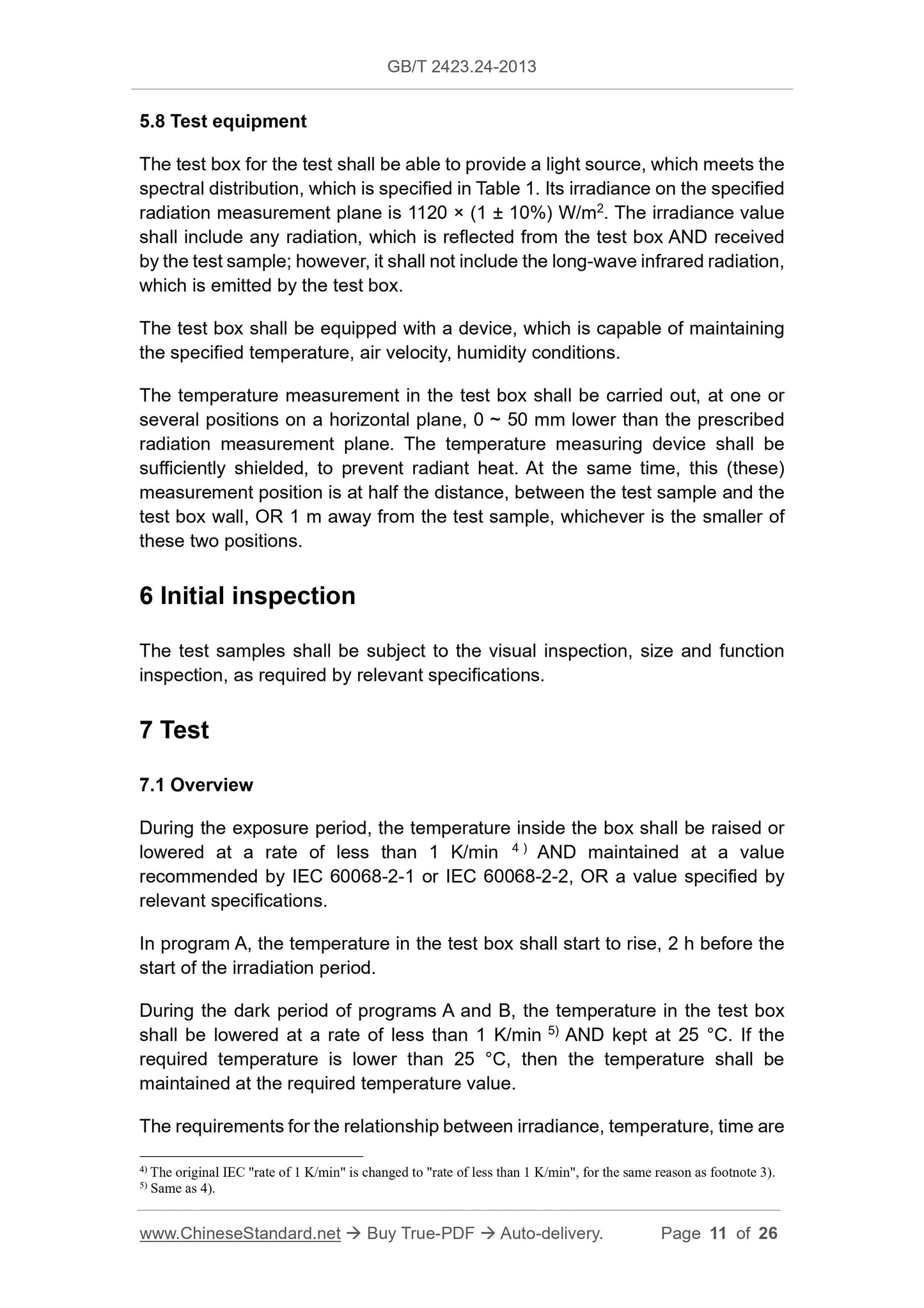
5.8 Test equipment
The test box for the test shall be able to provide a light source, which meets the
spectral distribution, which is specified in Table 1. Its irradiance on the specified
radiation measurement plane is 1120 × (1 ± 10%) W/m2. The irradiance value
shall include any radiation, which is reflected from the test box AND received
by the test sample; however, it shall not include the long-wave infrared radiation,
which is emitted by the test box.
The test box shall be equipped with a device, which is capable of maintaining
the specified temperature, air velocity, humidity conditions.
The temperature measurement in the test box shall be carried out, at one or
several positions on a horizontal plane, 0 ~ 50 mm lower than the prescribed
radiation measurement plane. The temperature measuring device shall be
sufficiently shielded, to prevent radiant heat. At the same time, this (these)
measurement position is at half the distance, between the test sample and the
test box wall, OR 1 m away from the test sample, whichever is the smaller of
these two positions.
6 Initial inspection
The test samples shall be subject to the visual inspection, size and function
inspection, as required by relevant specifications.
7 Test
7.1 Overview
During the exposure period, the temperature inside the box shall be raised or
lowered at a rate of less than 1 K/min 4 ) AND maintained at a value
recommended by IEC 60068-2-1 or IEC 60068-2-2, OR a value specified by
relevant specifications.
In program A, the temperature in the test box shall start to rise, 2 h before the
start of the irradiation period.
During the dark period of programs A and B, the temperature in the test box
shall be lowered at a rate of less than 1 K/min 5) AND kept at 25 °C. If the
required temperature is lower than 25 °C, then the temperature shall be
maintained at the required temperature value.
The requirements for the relationship between irradiance, temperature, time are
4) The original IEC "rate of 1 K/min" is changed to "rate of less than 1 K/min", for the same reason as footnote 3).
5) Same as 4).
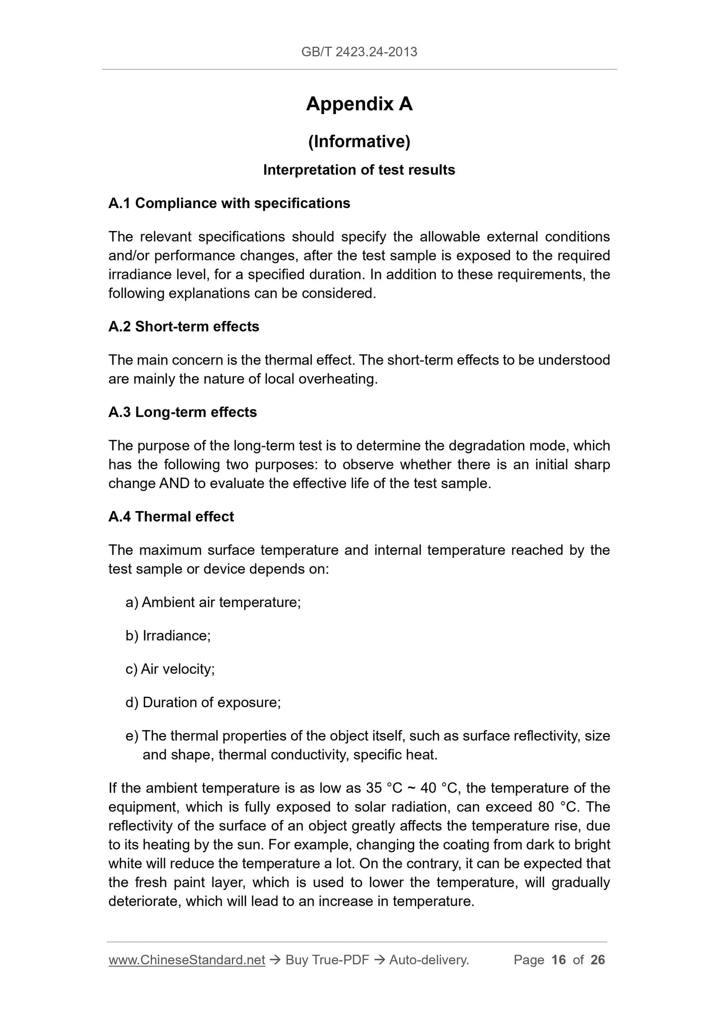
Appendix A
(Informative)
Interpretation of test results
A.1 Compliance with specifications
The relevant specifications should specify the allowable external conditions
and/or performance changes, after the test sample is exposed to the required
irradiance level, for a specified duration. In addition to these requirements, the
following explanations can be considered.
A.2 Short-term effects
The main concern is the thermal effect. The short-term effects to be understood
are mainly the nature of local overheating.
A.3 Long-term effects
The purpose of the long-term test is to determine the degradation mode, which
has the following two purposes: to observe whether there is an initial sharp
change AND to evaluate the effective life of the test sample.
A.4 Thermal effect
The maximum surface temperature and internal temperature reached by the
test sample or device depends on:
a) Ambient air temperature;
b) Irradiance;
c) Air velocity;
d) Duration of exposure;
e) The thermal properties of the object itself, such as surface reflectivity, size
and shape, thermal conductivity, specific heat.
If the ambient temperature is as low as 35 °C ~ 40 °C, the temperature of the
equipment, which is fully exposed to solar radiation, can exceed 80 °C. The
reflectivity of the surface of an object greatly affects the temperature rise, due
to its heating by the sun. For example, changing the coating from dark to bright
white will reduce the temperature a lot. On the contrary, it can be expected that
the fresh paint layer, which is used to lower the temperature, will gradually
deteriorate, which will lead to an increase in temperature.
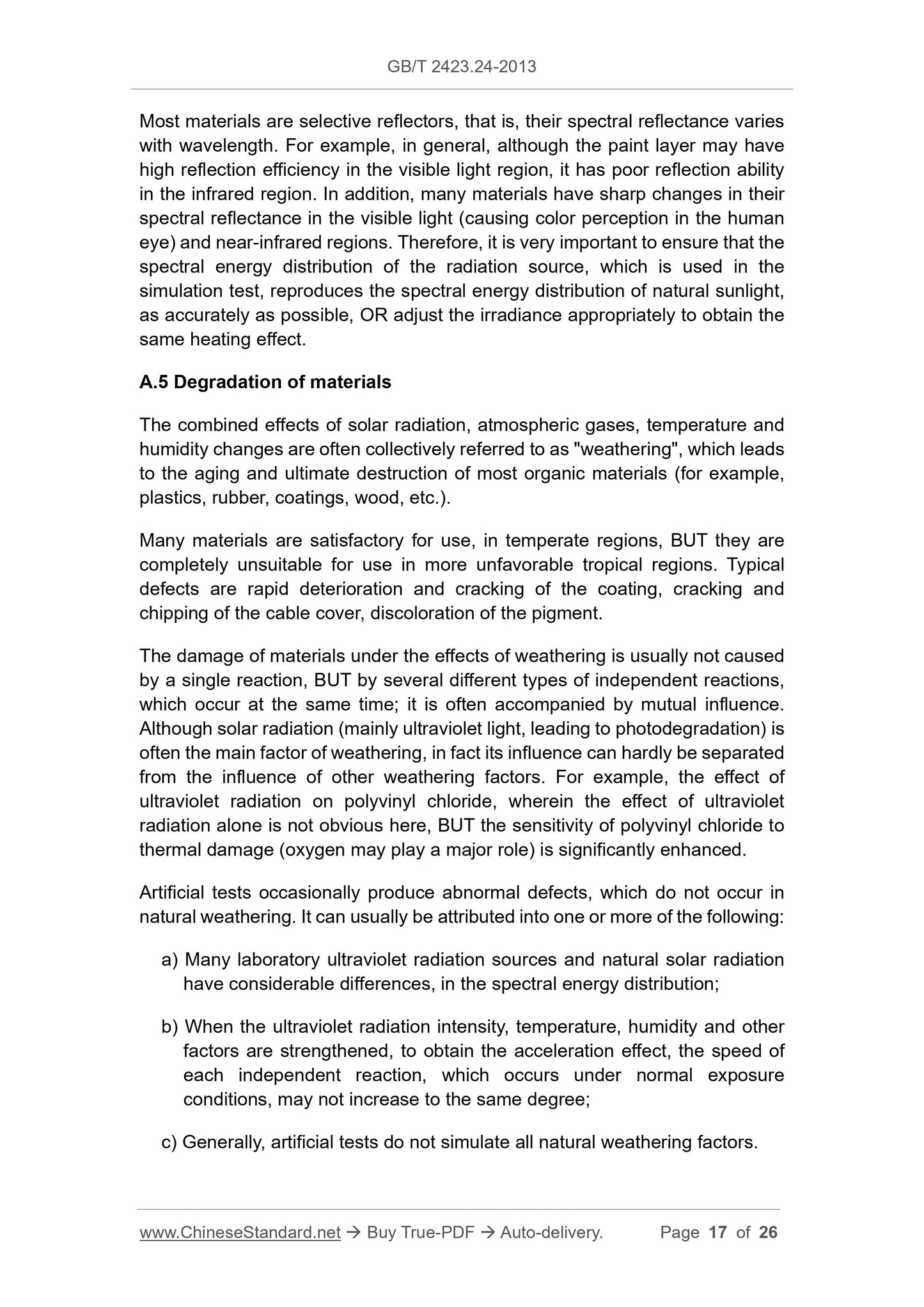
Most materials are selective reflectors, that is, their spectral reflectance varies
with wavelength. For example, in general, although the paint layer may have
high reflection efficiency in the visible light region, it has poor reflection ability
in the infrared region. In addition, many materials have sharp changes in their
spectral reflectance in the visible light (causing color perception in the human
eye) and near-infrared regions. Therefore, it is very important to ensure that the
spectral energy distribution of the radiation source, which is used in the
simulation test, reproduces the spectral energy distribution of natural sunlight,
as accurately as possible, OR adjust the irradiance appropriately to obtain the
same heating effect.
A.5 Degradation of materials
The combined effects of solar radiation, atmospheric gases, temperature and
humidity changes are often collectively referred to as "weathering", which leads
to the aging and ultimate destruction of most organic materials (for example,
plastics, rubber, coatings, wood, etc.).
Many materials are satisfactory for use, in temperate regions, BUT they are
completely unsuitable for use in more unfavorable tropical regions. Typical
defects are rapid deterioration and cracking of the coating, cracking and
chipping of the cable cover, discoloration of the pigment.
The damage of materials under the effects of weathering is usually not caused
by a single reaction, BUT by several different types of independent reactions,
which occur at the same time; it is often accompanied by mutual influence.
Although solar radiation (mainly ultraviolet light, leading to photodegradation) is
often the main factor of weathering, in fact its influence can hardly be separated
from the influence of other weathering factors. For example, the effect of
ultraviolet radiation on polyvinyl chloride, wherein the effect of ultraviolet
radiation alone is not obvious here, BUT the sensitivity of polyvinyl chloride to
thermal damage (oxygen may play a major role) is significantly enhanced.
Artificial tests occasionally produce abnormal defects, which do not occur in
natural weathering. It can usually be attributed into one or more of the following:
a) Many laboratory ultraviolet radiation sources and natural solar radiation
have considerable differences, in the spectral energy distribution;
b) When the ultraviolet radiation intensity, temperature, humidity and other
factors are strengthened, to obtain the acceleration effect, the speed of
each independent reaction, which occurs under normal exposure
conditions, may not increase to the same degree;
c) Generally, artificial tests do not simulate all natural weathering factors.
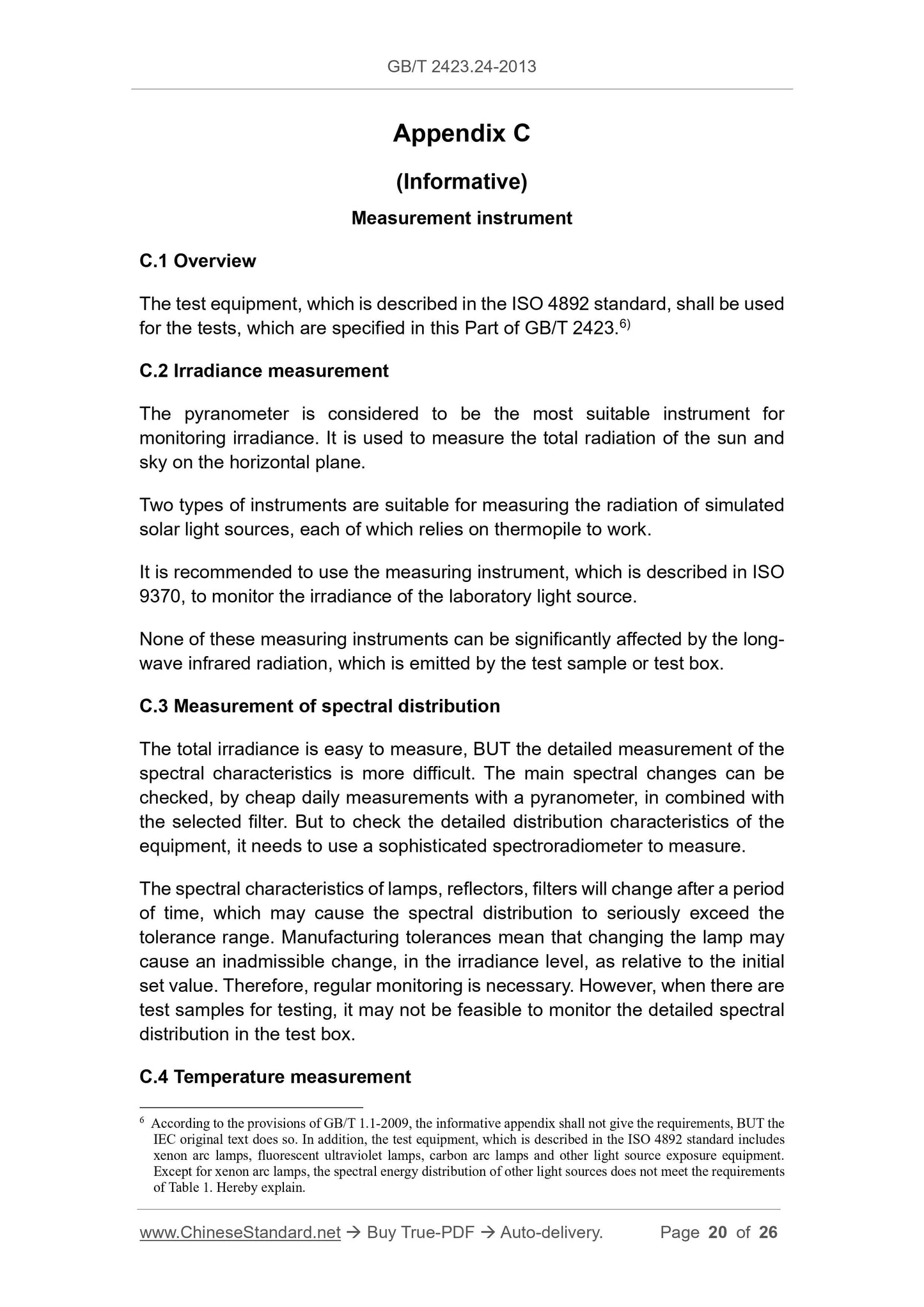
Appendix C
(Informative)
Measurement instrument
C.1 Overview
The test equipment, which is described in the ISO 4892 standard, shall be used
for the tests, which are specified in this Part of GB/T 2423.6)
C.2 Irradiance measurement
The pyranometer is considered to be the most suitable instrument for
monitoring irradiance. It is used to measure the total radiation of the sun and
sky on the horizontal plane.
Two types of instruments are suitable for measuring the radiation of simulated
solar light sources, each of which relies on thermopile to work.
It is recommended to use the measuring instrument, which is described in ISO
9370, to monitor the irradiance of the laboratory light source.
None of these measuring instruments can be significantly affected by the long-
wave infrared radiation, which is emitted by the test sample or test box.
C.3 Measurement of spectral distribution
The total irradiance is easy to measure, BUT the detailed measurement of the
spectral characteristics is more difficult. The main spectral changes can be
checked, by cheap daily measurements with a pyranometer, in combined with
the selected filter. But to check the detailed distribution characteristics of the
equipment, it needs to use a sophisticated spectroradiometer to measure.
The spectral characteristics of lamps, reflectors, filters will change after a period
of time, which may cause the spectral distribution to seriously exceed the
tolerance range. Manufacturing tolerances mean that changing the lamp may
cause an inadmissible change, in the irradiance level, as relative to the initial
set value. Therefore, regular monitoring is necessary. However, when there are
test samples for testing, it may not be feasible to monitor the detailed spectral
distribution in the test box.
C.4 Temperature measurement
6 According to the provisions of GB/T 1.1-2009, the informative appendix shall not give the requirements, BUT the
IEC original text does so. In addition, the test equipment, which is described in the ISO 4892 standard includes
xenon arc lamps, fluorescent ultraviolet lamps, carbon arc lamps and other light source exposure equipment.
Except for xenon arc lamps, the spectral energy distribution of other light sources does not meet the requirements
of Table 1. Hereby explain.
GB/T 2423.24-2013
GB
NATIONAL STANDARD OF THE
PEOPLE’S REPUBLIC OF CHINA
ICS 19.040
K 04
GB/T 2423.24-2013 / IEC 60068-2-5:2010
Replacing GB/T 2424.24-1995, GB/T 2424.14-1995
Environmental testing - Part 2: Test methods - Test Sa:
Simulated solar radiation at ground level and
guidance for solar radiation testing
(IEC 60068-2-5:2010, Environmental testing - Part 2-5: Tests - Test Sa:
Simulated solar radiation at ground level and guidance for solar radiation
testi...
Delivery: 9 seconds. Download (& Email) true-PDF + Invoice.
Get Quotation: Click GB/T 2423.24-2013 (Self-service in 1-minute)
Historical versions (Master-website): GB/T 2423.24-2013
Preview True-PDF (Reload/Scroll-down if blank)
GB/T 2423.24-2013
GB
NATIONAL STANDARD OF THE
PEOPLE’S REPUBLIC OF CHINA
ICS 19.040
K 04
GB/T 2423.24-2013 / IEC 60068-2-5:2010
Replacing GB/T 2424.24-1995, GB/T 2424.14-1995
Environmental testing - Part 2: Test methods - Test Sa:
Simulated solar radiation at ground level and
guidance for solar radiation testing
(IEC 60068-2-5:2010, Environmental testing - Part 2-5: Tests - Test Sa:
Simulated solar radiation at ground level and guidance for solar radiation
testing, IDT)
ISSUED ON: NOVEMBER 12, 2013
IMPLEMENTED ON: MARCH 07, 2014
Issued by: General Administration of Quality Supervision, Inspection and
Quarantine of PRC;
Standardization Administration of PRC.
Table of Contents
Foreword ... 3
1 Scope ... 6
2 Normative references ... 6
3 Terms and definitions ... 6
4 General description ... 8
5 Test conditions ... 9
6 Initial inspection ... 11
7 Test ... 11
8 Final inspection ... 13
9 Information to be given by relevant specifications ... 14
10 Information to be given in the test report ... 14
Appendix A (Informative) Interpretation of test results ... 16
Appendix B (Informative) Radiation source ... 18
Appendix C (Informative) Measurement instrument ... 20
Appendix NA (Informative) Composition of GB/T 2423 ... 22
References ... 26
Environmental testing - Part 2: Test methods - Test Sa:
Simulated solar radiation at ground level and
guidance for solar radiation testing
1 Scope
This part of GB/T 2423 provides guidance for testing equipment or components,
under solar radiation conditions.
The purpose of the test is to check the extent to which equipment or
components are affected by solar radiation.
The comprehensive test method can detect changes in electrical, mechanical
or other physical properties.
2 Normative references
The following documents are essential to the application of this document. For
the dated documents, only the versions with the dates indicated are applicable
to this document; for the undated documents, only the latest version (including
all the amendments) is applicable to this standard.
IEC 60068-1 Environmental testing - Part 1: General and guidance
IEC 60068-2-1 Environmental testing - Part 2-1: Tests - Test A: Cold
IEC 60068-2-2 Environmental testing - Part 2-2: Tests - Test B: Dry heat
IEC 60068-2-78 Environmental testing - Part 2-78: Tests - Test Cab: Damp
heat, steady state
CIE 85:19891) Solar spectral irradiance
3 Terms and definitions
The terms and definitions as defined in IEC 60068-1, as well as the following
terms and definitions, apply to this document.
1 The original text of IEC is "CIE 85:1985", which is wrong in the year. It is corrected here to "CIE 85:1989".
If required, the recommended value of IEC 60068-2-78 shall be used first.
The relevant specifications shall specify the humidity during the following test
AND whether it needs to be maintained:
a) Only during the irradiation period;
b) Only in the dark period;
c) The entire test duration.
5.4 Ozone and other polluting gases
The ozone, which is produced by the short-wave ultraviolet rays in the test
radiation source, is usually discharged out of the test box, by a filter that corrects
the spectral energy distribution. Because ozone and other polluting gases will
significantly affect the degradation process of certain materials, it is important
to exhaust these gases from the test box, unless otherwise required by relevant
specifications.
5.5 Surface contamination
Dust and other surface contaminants can significantly change the absorption
characteristics of the irradiated surface. Unless otherwise required, the test
sample should be tested, under clean conditions. However, if the impact of
surface contaminants is to be evaluated, relevant specifications should include
necessary information such as surface preparation.
5.6 Installation of test sample
The test sample shall be installed on a raised support, turntable or a special
base, which has known thermal conductivity and heat capacity, in the test box,
according to the relevant specifications. There shall be sufficient spacing
between test samples, to avoid the radiation from the light source OR
secondary radiant heat. The temperature sensor should be attached to the test
sample, as required.
5.7 Test facility
The optical parts, lamps, reflectors, filters of the test equipment shall be kept
clean.
The irradiance on the specified measurement plane shall be measured, before
each test.
Any specified auxiliary environmental conditions, such as ambient temperature,
humidity, air flow rate or other parameters, shall be continuously monitored,
throughout the test period.
5.8 Test equipment
The test box for the test shall be able to provide a light source, which meets the
spectral distribution, which is specified in Table 1. Its irradiance on the specified
radiation measurement plane is 1120 × (1 ± 10%) W/m2. The irradiance value
shall include any radiation, which is reflected from the test box AND received
by the test sample; however, it shall not include the long-wave infrared radiation,
which is emitted by the test box.
The test box shall be equipped with a device, which is capable of maintaining
the specified temperature, air velocity, humidity conditions.
The temperature measurement in the test box shall be carried out, at one or
several positions on a horizontal plane, 0 ~ 50 mm lower than the prescribed
radiation measurement plane. The temperature measuring device shall be
sufficiently shielded, to prevent radiant heat. At the same time, this (these)
measurement position is at half the distance, between the test sample and the
test box wall, OR 1 m away from the test sample, whichever is the smaller of
these two positions.
6 Initial inspection
The test samples shall be subject to the visual inspection, size and function
inspection, as required by relevant specifications.
7 Test
7.1 Overview
During the exposure period, the temperature inside the box shall be raised or
lowered at a rate of less than 1 K/min 4 ) AND maintained at a value
recommended by IEC 60068-2-1 or IEC 60068-2-2, OR a value specified by
relevant specifications.
In program A, the temperature in the test box shall start to rise, 2 h before the
start of the irradiation period.
During the dark period of programs A and B, the temperature in the test box
shall be lowered at a rate of less than 1 K/min 5) AND kept at 25 °C. If the
required temperature is lower than 25 °C, then the temperature shall be
maintained at the required temperature value.
The requirements for the relationship between irradiance, temperature, time are
4) The original IEC "rate of 1 K/min" is changed to "rate of less than 1 K/min", for the same reason as footnote 3).
5) Same as 4).
Appendix A
(Informative)
Interpretation of test results
A.1 Compliance with specifications
The relevant specifications should specify the allowable external conditions
and/or performance changes, after the test sample is exposed to the required
irradiance level, for a specified duration. In addition to these requirements, the
following explanations can be considered.
A.2 Short-term effects
The main concern is the thermal effect. The short-term effects to be understood
are mainly the nature of local overheating.
A.3 Long-term effects
The purpose of the long-term test is to determine the degradation mode, which
has the following two purposes: to observe whether there is an initial sharp
change AND to evaluate the effective life of the test sample.
A.4 Thermal effect
The maximum surface temperature and internal temperature reached by the
test sample or device depends on:
a) Ambient air temperature;
b) Irradiance;
c) Air velocity;
d) Duration of exposure;
e) The thermal properties of the object itself, such as surface reflectivity, size
and shape, thermal conductivity, specific heat.
If the ambient temperature is as low as 35 °C ~ 40 °C, the temperature of the
equipment, which is fully exposed to solar radiation, can exceed 80 °C. The
reflectivity of the surface of an object greatly affects the temperature rise, due
to its heating by the sun. For example, changing the coating from dark to bright
white will reduce the temperature a lot. On the contrary, it can be expected that
the fresh paint layer, which is used to lower the temperature, will gradually
deteriorate, which will lead to an increase in temperature.
Most materials are selective reflectors, that is, their spectral reflectance varies
with wavelength. For example, in general, although the paint layer may have
high reflection efficiency in the visible light region, it has poor reflection ability
in the infrared region. In addition, many materials have sharp changes in their
spectral reflectance in the visible light (causing color perception in the human
eye) and near-infrared regions. Therefore, it is very important to ensure that the
spectral energy distribution of the radiation source, which is used in the
simulation test, reproduces the spectral energy distribution of natural sunlight,
as accurately as possible, OR adjust the irradiance appropriately to obtain the
same heating effect.
A.5 Degradation of materials
The combined effects of solar radiation, atmospheric gases, temperature and
humidity changes are often collectively referred to as "weathering", which leads
to the aging and ultimate destruction of most organic materials (for example,
plastics, rubber, coatings, wood, etc.).
Many materials are satisfactory for use, in temperate regions, BUT they are
completely unsuitable for use in more unfavorable tropical regions. Typical
defects are rapid deterioration and cracking of the coating, cracking and
chipping of the cable cover, discoloration of the pigment.
The damage of materials under the effects of weathering is usually not caused
by a single reaction, BUT by several different types of independent reactions,
which occur at the same time; it is often accompanied by mutual influence.
Although solar radiation (mainly ultraviolet light, leading to photodegradation) is
often the main factor of weathering, in fact its influence can hardly be separated
from the influence of other weathering factors. For example, the effect of
ultraviolet radiation on polyvinyl chloride, wherein the effect of ultraviolet
radiation alone is not obvious here, BUT the sensitivity of polyvinyl chloride to
thermal damage (oxygen may play a major role) is significantly enhanced.
Artificial tests occasionally produce abnormal defects, which do not occur in
natural weathering. It can usually be attributed into one or more of the following:
a) Many laboratory ultraviolet radiation sources and natural solar radiation
have considerable differences, in the spectral energy distribution;
b) When the ultraviolet radiation intensity, temperature, humidity and other
factors are strengthened, to obtain the acceleration effect, the speed of
each independent reaction, which occurs under normal exposure
conditions, may not increase to the same degree;
c) Generally, artificial tests do not simulate all natural weathering factors.
Appendix C
(Informative)
Measurement instrument
C.1 Overview
The test equipment, which is described in the ISO 4892 standard, shall be used
for the tests, which are specified in this Part of GB/T 2423.6)
C.2 Irradiance measurement
The pyranometer is considered to be the most suitable instrument for
monitoring irradiance. It is used to measure the total radiation of the sun and
sky on the horizontal plane.
Two types of instruments are suitable for measuring the radiation of simulated
solar light sources, each of which relies on thermopile to work.
It is recommended to use the measuring instrument, which is described in ISO
9370, to monitor the irradiance of the laboratory light source.
None of these measuring instruments can be significantly affected by the long-
wave infrared radiation, which is emitted by the test sample or test box.
C.3 Measurement of spectral distribution
The total irradiance is easy to measure, BUT the detailed measurement of the
spectral characteristics is more difficult. The main spectral changes can be
checked, by cheap daily measurements with a pyranometer, in combined with
the selected filter. But to check the detailed distribution characteristics of the
equipment, it needs to use a sophisticated spectroradiometer to measure.
The spectral characteristics of lamps, reflectors, filters will change after a period
of time, which may cause the spectral distribution to seriously exceed the
tolerance range. Manufacturing tolerances mean that changing the lamp may
cause an inadmissible change, in the irradiance level, as relative to the initial
set value. Therefore, regular monitoring is necessary. However, when there are
test samples for testing, it may not be feasible to monitor the detailed spectral
distribution in the test box.
C.4 Temperature measurement
6 According to the provisions of GB/T 1.1-2009, the informative appendix shall not give the requirements, BUT the
IEC original text does so. In addition, the test equipment, which is described in the ISO 4892 standard includes
xenon arc lamps, fluorescent ultraviolet lamps, carbon arc lamps and other light source exposure equipment.
Except for xenon arc lamps, the spectral energy distribution of other light sources does not meet the requirements
of Table 1. Hereby explain.
GB/T 2423.24-2013
GB
NATIONAL STANDARD OF THE
PEOPLE’S REPUBLIC OF CHINA
ICS 19.040
K 04
GB/T 2423.24-2013 / IEC 60068-2-5:2010
Replacing GB/T 2424.24-1995, GB/T 2424.14-1995
Environmental testing - Part 2: Test methods - Test Sa:
Simulated solar radiation at ground level and
guidance for solar radiation testing
(IEC 60068-2-5:2010, Environmental testing - Part 2-5: Tests - Test Sa:
Simulated solar radiation at ground level and guidance for solar radiation
testi...
Share