1
/
of
5
PayPal, credit cards. Download editable-PDF and invoice in 1 second!
GB/T 25123.3-2011 English PDF (GBT25123.3-2011)
GB/T 25123.3-2011 English PDF (GBT25123.3-2011)
Regular price
$205.00 USD
Regular price
Sale price
$205.00 USD
Unit price
/
per
Shipping calculated at checkout.
Couldn't load pickup availability
Delivery: 3 seconds. Download true-PDF + Invoice.
Get QUOTATION in 1-minute: Click GB/T 25123.3-2011
Historical versions: GB/T 25123.3-2011
Preview True-PDF (Reload/Scroll if blank)
GB/T 25123.3-2011: Electric traction -- Rotating electrical machines for rail and road vehicles -- Part 3: Determination of the total losses of convertor-fed alternating current motors by summation of the component losses
GB/T 25123.3-2011
GB
NATIONAL STANDARD OF THE
PEOPLE’S REPUBLIC OF CHINA
ICS 29.280
S 35
GB/T 25123.3-2011 / IEC 60349-3:1995
Electric traction - Rotating electrical machines for rail and
road vehicles - Part 3: Determination of the total losses of
convertor-fed alternating current motors by summation of
the component losses
(IEC 60349-3:1995, IDT)
ISSUED ON: DECEMBER 30, 2011
IMPLEMENTED ON: JUNE 01, 2012
Issued by: General Administration of Quality Supervision, Inspection and
Quarantine of the People's Republic of China;
Standardization Administration of the People's Republic of China.
Table of Contents
Foreword ... 3
1 Scope ... 5
2 Instrumentation ... 5
3 Summation of losses ... 7
3.1 The total losses are the sum of the following component losses ... 7
3.2 Determination of the component losses ... 7
Annex A (informative) The equivalent circuit of an asynchronous motor ... 11
Annex B (informative) Stray load loss ... 19
Bibliography ... 21
Foreword
GB/T 25123 "Electric traction - Rotating electrical machines for rail and road vehicles"
consists of the following parts:
- Part 1: Machines others than electronic convertor-fed alternating current motors;
- Part 2: Electronic convertor-fed alternating current motors;
- Part 3: Determination of the total losses of convertor-fed alternating current motors
by summation of the component losses.
This Part is Part 3 of GB/T 25123.
This Part was drafted in accordance with the rules given in GB/T 1.1-2009.
This Part uses redrafting method to modify and adopt IEC 60349-3:1995 "Electric
traction - Rotating electrical machines for rail and road vehicles - Part 3: Determination
of the total losses of convertor-fed alternating current motors by summation of the
component losses".
This Part made the following editorial changes:
- According to the requirements of GB/T 1.1-2009, the formula numbers (1)~(8) of
IEC 60349-3:1995 are numbered as (A.1)~(A.9) in this Part. Add numbers to the
formulas in 3.2.1.2 and Annex B;
- Correct the following errors in Table A.2 of the original text:
a) In the formula of item 15, "(1)/(7)" in the original text is changed to "1/(7)";
b) In the formula of item 19, "(17)-(18)" in the original text is changed to
"(17)+(18)";
c) In the formula of item 24, "(23)/(2)" in the original text is changed to "(23)+(2)";
d) In the formula of item 27, "(22)2" in the original text is changed to "(22)".
This Part was proposed by Ministry of Railways of the People's Republic of China.
This Part shall be under the jurisdiction of National Technical Committee on Traction
Electrical Equipment and Systems of Standardization Administration of China
(SAC/TC 278).
Main drafting organizations of this Part: Zhuzhou CSR Times Electric Co., Ltd.
The drafting organizations of this Part: CSR Zhuzhou Electric Co., Ltd. and Yongji
Xinshisu Electric Co., Ltd.
Electric traction - Rotating electrical machines for rail and
road vehicles - Part 3: Determination of the total losses of
convertor-fed alternating current motors by summation of
the component losses
1 Scope
This Part of GB/T 25123 applies to machines that comply with GB/T 25123.2.
The total losses of a convertor-fed motor may be determined by summation of the
component losses derived from no-load and load tests. The total input power is the sum
of the power at the fundamental frequency and at all other frequencies. In all practical
cases the latter input includes the losses resulting from the voltage and current
harmonics in the convertor supply by using suitable instrumentation it can be derived
from measurement of the total and fundamental frequency power inputs when the
machine is on load.
The losses supplied at the fundamental frequency cannot be measured directly and so
are derived from measurement of the fundamental frequency load current and the
fundamental frequency no-load power input.
2 Instrumentation
The extra loss due to operation on a convertor supply is obtained from the difference of
the total and fundamental frequency power input on load.
The power inputs shall be measured simultaneously on each phase by a digital sampling
instrument. Measurement on all three phases is preferred but the two wattmeter method
is permissible as an alternative.
The total power is obtained from the product of voltage and current over a period of
time and the fundamental power from a Fourier transform using the same sampling.
It is necessary to consider the accuracy of the whole instrument chain considering both
amplification and phase shift errors over the desired frequency range. As the power
factor of the harmonics is generally very low (less than 0.l for voltage imposed
asynchronous systems) particular attention is drawn to the need for minimum phase
angle errors.
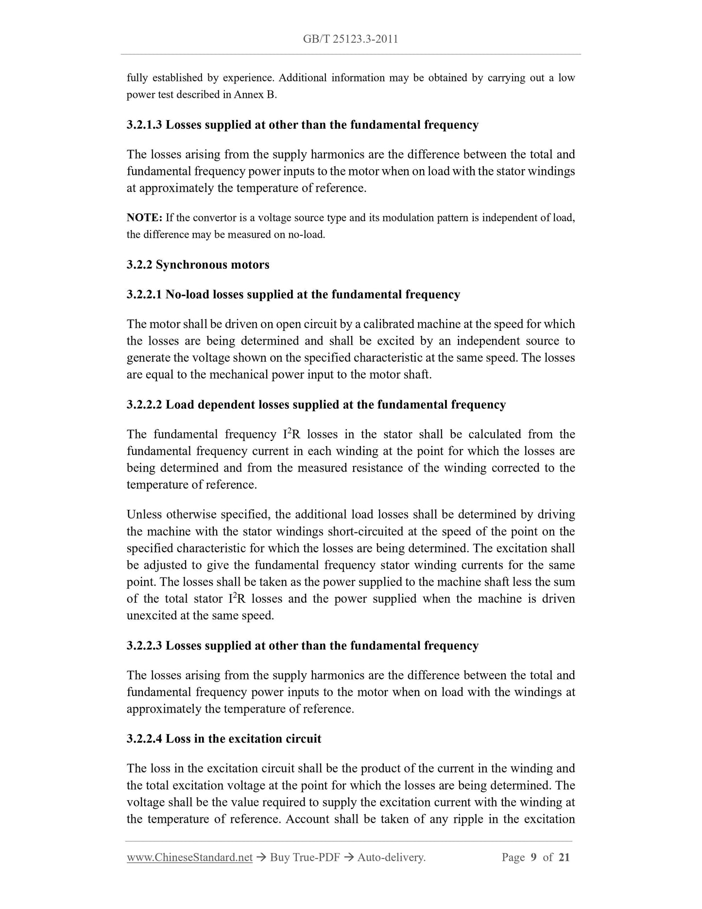
fully established by experience. Additional information may be obtained by carrying out a low
power test described in Annex B.
3.2.1.3 Losses supplied at other than the fundamental frequency
The losses arising from the supply harmonics are the difference between the total and
fundamental frequency power inputs to the motor when on load with the stator windings
at approximately the temperature of reference.
NOTE: If the convertor is a voltage source type and its modulation pattern is independent of load,
the difference may be measured on no-load.
3.2.2 Synchronous motors
3.2.2.1 No-load losses supplied at the fundamental frequency
The motor shall be driven on open circuit by a calibrated machine at the speed for which
the losses are being determined and shall be excited by an independent source to
generate the voltage shown on the specified characteristic at the same speed. The losses
are equal to the mechanical power input to the motor shaft.
3.2.2.2 Load dependent losses supplied at the fundamental frequency
The fundamental frequency I2R losses in the stator shall be calculated from the
fundamental frequency current in each winding at the point for which the losses are
being determined and from the measured resistance of the winding corrected to the
temperature of reference.
Unless otherwise specified, the additional load losses shall be determined by driving
the machine with the stator windings short-circuited at the speed of the point on the
specified characteristic for which the losses are being determined. The excitation shall
be adjusted to give the fundamental frequency stator winding currents for the same
point. The losses shall be taken as the power supplied to the machine shaft less the sum
of the total stator I2R losses and the power supplied when the machine is driven
unexcited at the same speed.
3.2.2.3 Losses supplied at other than the fundamental frequency
The losses arising from the supply harmonics are the difference between the total and
fundamental frequency power inputs to the motor when on load with the windings at
approximately the temperature of reference.
3.2.2.4 Loss in the excitation circuit
The loss in the excitation circuit shall be the product of the current in the winding and
the total excitation voltage at the point for which the losses are being determined. The
voltage shall be the value required to supply the excitation current with the winding at
the temperature of reference. Account shall be taken of any ripple in the excitation
Share
