1
/
of
12
PayPal, credit cards. Download editable-PDF and invoice in 1 second!
GB/T 25127.2-2020 English PDF (GB/T25127.2-2020)
GB/T 25127.2-2020 English PDF (GB/T25127.2-2020)
Regular price
$275.00 USD
Regular price
Sale price
$275.00 USD
Unit price
/
per
Shipping calculated at checkout.
Couldn't load pickup availability
Delivery: 3 seconds. Download true-PDF + Invoice.
Get Quotation: Click GB/T 25127.2-2020 (Self-service in 1-minute)
Historical versions (Master-website): GB/T 25127.2-2020
Preview True-PDF (Reload/Scroll-down if blank)
GB/T 25127.2-2020: Low ambient temperature air source heat pump (water chilling) packages - Part 2: Heat pump (water chilling) packages for household and similar application
GB/T 25127.2-2020.Low ambient temperature air source heat pump (chilled water) units Part 2.Heat pump (chilled water) units for household and similar purposes
National Standard of the People's Republic of China
Replaces GB/T 25127.2-2010
State Administration for Market Regulation
The National Standardization Administration issued
1 Scope
This part of GB/T 25127 specifies the low ambient temperature air source heat pumps (cold water) for household and similar purposes driven by electric motors.
The type and basic parameters, technical requirements, test methods, inspection rules, and marking, packaging, transportation, etc. of the unit (hereinafter referred to as the "unit").
and storage.
This standard is applicable to equipment with a nominal heating capacity of no more than 35 kW, using air as the heat (cold) source, and operating in an ambient temperature of no less than -25°C.
The unit for producing hot (cold) water. Other similar units can refer to this.
2 Normative references
The following documents are essential for the application of this document. For any dated referenced document, only the dated version applies to this document.
For any undated referenced documents, the latest version (including all amendments) shall apply to this document.
GB/T 2423.17 Environmental testing for electric and electronic products Part 2.Test methods Test Ka. Salt spray
GB 2894-2008 Safety signs and their use guidelines
GB/T 3785 (all parts) Electroacoustic sound level meter
GB/T 4208-2017 Enclosure protection degree (IP code)
GB 4706.1-2005 Safety of household and similar electrical appliances Part 1.General requirements
GB 4706.32-2012 Safety of household and similar electrical appliances - Particular requirements for heat pumps, air conditioners and dehumidifiers
GB/T 5226.1-2019 Electrical safety of machinery Electrical equipment of machinery Part 1.General technical requirements
GB/T 9237 Safety and environmental requirements for refrigeration systems and heat pumps
GB/T 10870-2014 Performance test method for vapor compression cycle chillers (heat pumps)
GB/T 13306 Labels
GB/T 13384 General technical requirements for packaging of electromechanical products
GB/T 18430.1-2007 Vapor compression cycle chillers (heat pumps) Part 1.Chillers for industrial or commercial and similar purposes
Water (heat pump) unit
GB/T 26572 Limit requirements for restricted substances in electronic and electrical products
JB/T 4330-1999 Determination of noise from refrigeration and air-conditioning equipment
JB/T 7249 Terminology of Refrigeration Equipment
NB/T 47012 Pressure vessels for refrigeration equipment
3 Terms and definitions
The terms and definitions defined in JB/T 7249 and the following apply to this document.
4 Types and basic parameters
4.1 Type
4.1.1 According to the structural type, it is divided into.
---Integral type;
---split type.
4.1.2 According to the unit function, it is divided into.
--- Single heating type (including units used simultaneously or switched with auxiliary electric heating);
---Cold and warm type.
4.1.3 According to the end of the unit matching, it is divided into.
---Floor radiation type;
---Fan coil type;
---Radiator type;
---other.
4.1.4 According to the power supply used by the unit, it is divided into.
---Single-phase AC power supply;
---Three-phase AC power supply.
4.2 Model
The method of compiling the unit model may be determined by the manufacturer, but the model should reflect the heating capacity of the unit under the nominal operating conditions of this part.
4.3 Basic parameters
4.3.1 The power supply of the unit is rated at 220V or 380V and rated at 50Hz.
4.3.2 The unit should be able to operate normally under the following conditions.
---Ambient temperature of single heat type unit. -25℃~21℃;
---Ambient temperature for cooling and heating units. -25℃~43℃.
4.3.3 The test parameters of the unit are shown in Table 1.
4.3.4 The performance coefficient of the unit and its limit values are shown in Table 2.
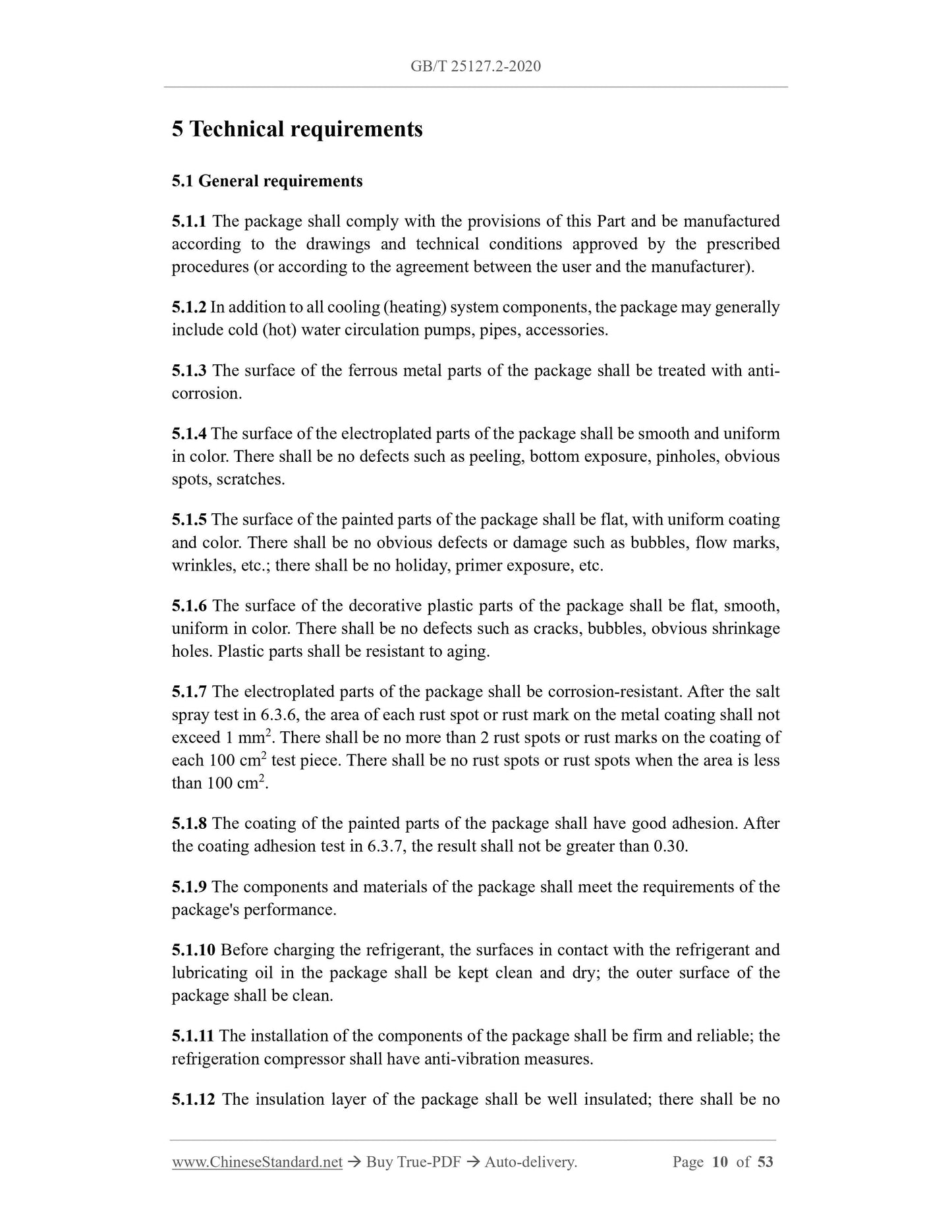
5 Technical requirements
5.1 General requirements
5.1.1 The unit shall comply with the provisions of this Part and be constructed in accordance with the drawings and technical specifications approved through the prescribed procedures (or as agreed between the user and the manufacturer).
manufacture.
5.1.2 In addition to all refrigeration (heating) system components, the unit may also generally include cold (hot) water circulation pumps, pipes and accessories.
5.1.3 The surface of the ferrous metal parts of the unit should be treated with anti-corrosion treatment.
5.1.4 The surface of the electroplated parts of the unit should be smooth and uniform in color, and should not have defects such as peeling, exposed bottom, pinholes, obvious spots and scratches.
5.1.5 The surface of the unit's painted parts should be flat, with uniform coating and color, and should not have obvious defects or damage such as bubbles, flow marks, wrinkles, etc.
There are situations such as missing paint and exposed primer.
5.1.6 The surface of decorative plastic parts of the unit should be flat and smooth, with uniform color, and should not have defects such as cracks, bubbles and obvious shrinkage holes.
Resistant to ageing.
5.1.7 The electroplated parts of the unit shall be corrosion resistant. After the salt spray test in 6.3.6, the area of each rust spot or rust mark on the metal coating shall not exceed
For specimens with an area of more than 1 mm2, there shall be no more than 2 rust spots or rust marks per 100 cm2 of the coating. For specimens with an area of less than 100 cm2, there shall be no rust spots or rust marks.
5.1.8 The coating of the unit painted parts should have good adhesion. After the coating adhesion test in 6.3.7, the result should not be greater than 0.30.
5.1.9 The components and materials of the unit should meet the performance requirements.
5.1.10 Before charging the refrigerant, the surfaces inside the unit that come into contact with the refrigerant and lubricating oil should be kept clean and dry, and the external surfaces of the unit should be clean.
5.1.11 The installation of all components of the unit should be firm and reliable, and the refrigeration compressor should have anti-vibration measures.
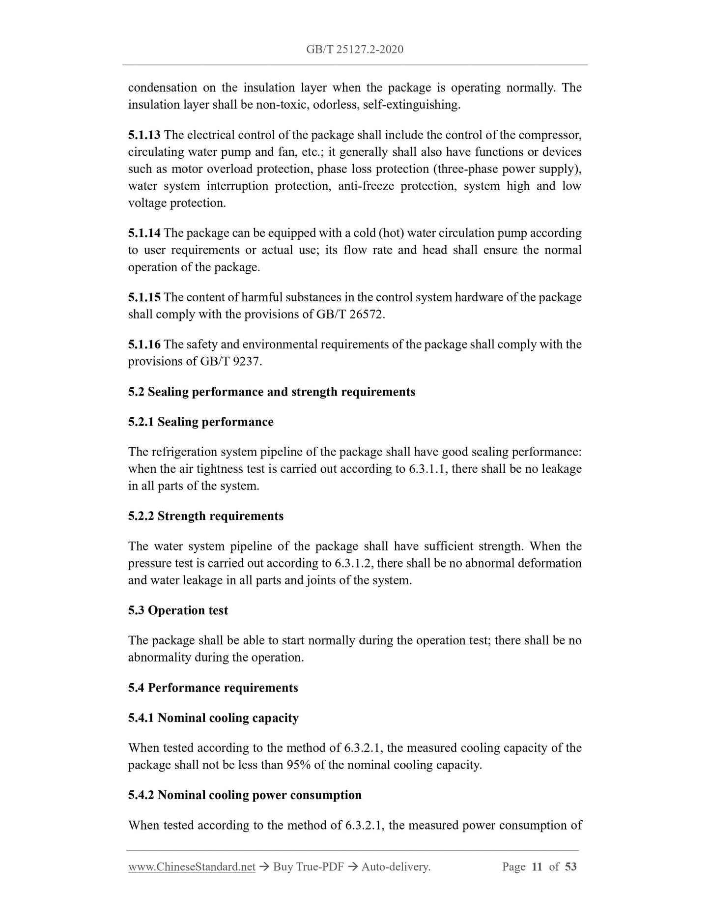
5.1.12 The heat insulation layer of the unit should have good heat insulation performance. During normal operation, there should be no condensation on the heat insulation layer. It should be non-toxic, odorless and self-contained.
Turn off performance.
5.1.13 The electrical control of the unit shall include the control of the compressor, circulating water pump and fan, etc., and shall generally also have motor overload protection, short circuit protection and other functions.
Phase protection (three-phase power supply), water system short-circuit protection, anti-freeze protection, system high and low voltage protection and other functions or devices.
5.1.14 The unit can be equipped with a cold (hot) water circulation pump according to user requirements or actual use. Its flow rate and head should ensure the normal operation of the unit.
5.1.15 The content of harmful substances in the unit shall comply with the requirements of GB/T 26572.
5.1.16 The safety and environmental requirements of the unit shall comply with the provisions of GB/T 9237.
5.2 Sealing performance and strength requirements
5.2.1 Sealing performance
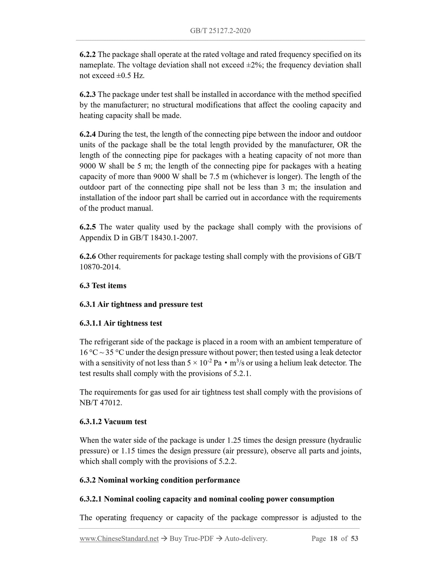
The refrigeration system pipelines of the unit should have good sealing performance; when conducting the air tightness test according to 6.3.1.1, there should be no
leakage.
5.2.2 Strength requirements
The water system pipeline of the unit should have sufficient strength. When the pressure test is carried out according to 6.3.1.2, there should be no abnormality in all parts and joints of the system.
Deformation and water leakage.
5.3 Operation test
The unit should be able to start normally during the operation test and there should be no abnormalities during the operation.
5.4 Performance requirements
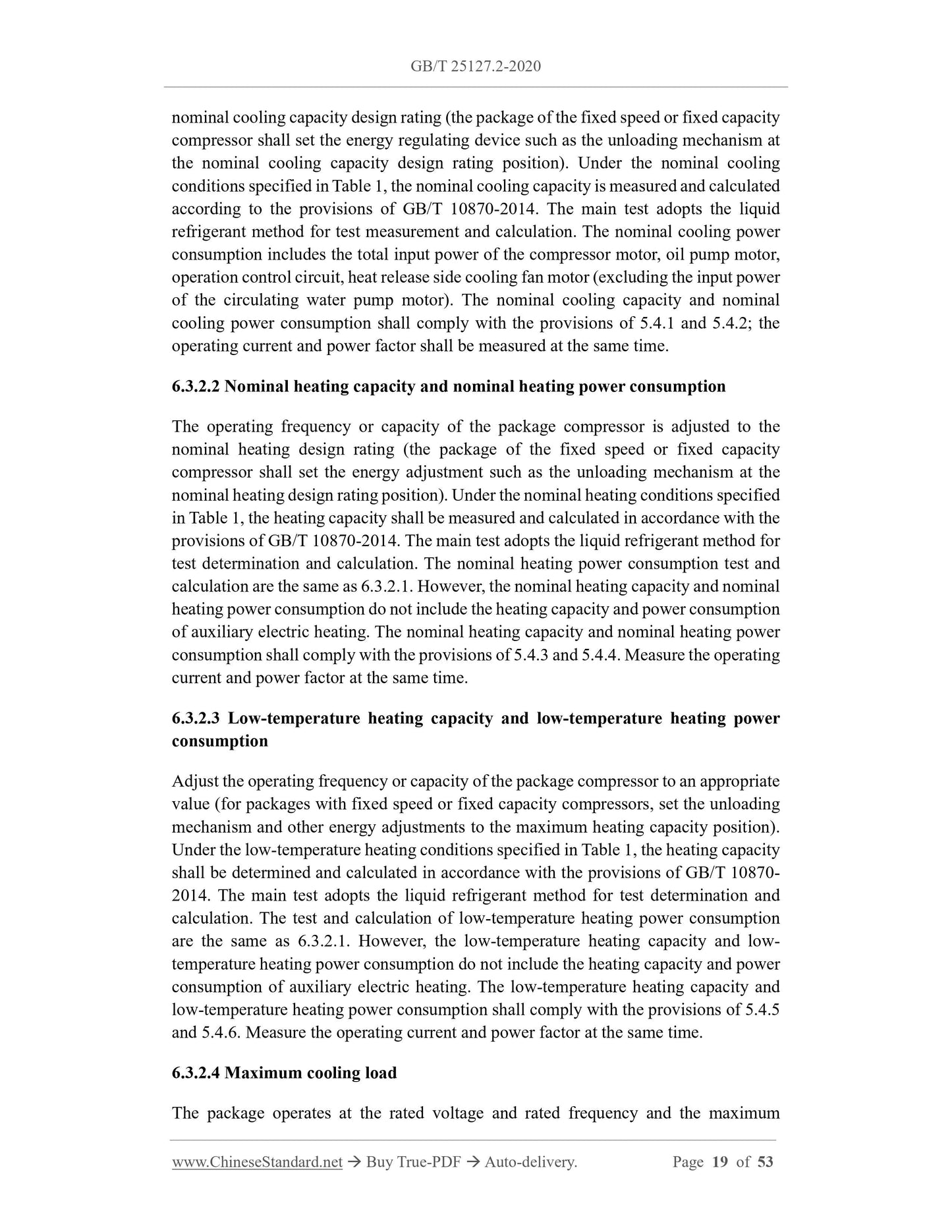
5.4.1 Nominal cooling capacity
When tested according to the method in 6.3.2.1, the actual cooling capacity of the unit shall not be less than 95% of the indicated nominal cooling capacity.
5.4.2 Nominal cooling power consumption
When tested according to the method in 6.3.2.1, the actual power consumption of the unit shall not exceed 110% of the stated value of the nominal refrigeration power consumption.
5.4.3 Nominal heating capacity
When tested according to the methods in 6.3.2.2 and Appendix A, the measured heating capacity of the unit shall not be less than 95% of the indicated value of the nominal heating capacity.
5.4.4 Nominal heating power consumption
When tested according to the method in 6.3.2.2 and Appendix A, the actual heating power consumption of the unit shall not be greater than the indicated value of the nominal heating power consumption.
110% of.
5.4.5 Low temperature heating capacity
When tested according to the method in 6.3.2.3 and Appendix A, the actual heating capacity of the unit shall not be less than 95% of the indicated value of low-temperature heating capacity and shall not
Lower than 80% of the nominal heating capacity stated in 5.4.3.
5.4.6 Low temperature heating power consumption
When tested according to the method in 6.3.2.3 and Appendix A, the actual heating power consumption of the unit shall not be greater than the indicated value of low-temperature heating power consumption.
110% of.
5.4.7 Maximum refrigeration load
When tested according to the method in 6.3.2.4, the motor, electrical component connections and other parts should be able to operate normally.
5.4.8 Minimum cooling load
When testing according to the method in 6.3.2.5, the components of the unit should not be damaged, the low-pressure, antifreeze and overload protectors should not trip, and the unit should operate normally.
Work.
5.4.9 Defrosting
When tested according to the method in 6.3.2.6, the unit shall meet the following requirements.
---Safety protection components should not be activated and stop running;
---Defrosting should be automatic, function normally, and be thorough, and the melted water during defrosting should be able to be discharged normally;
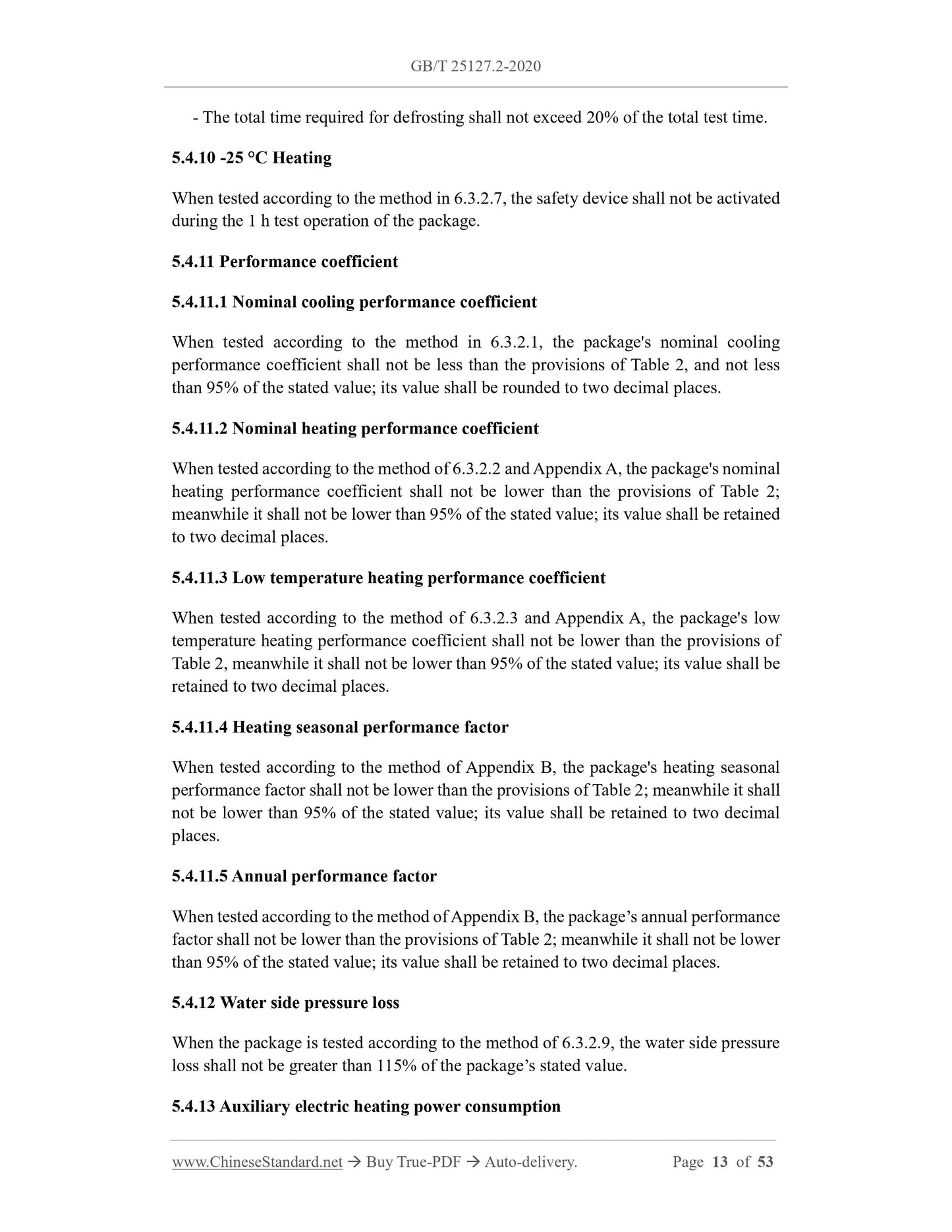
---The total time required for defrosting should not exceed 20% of the total test time.
5.4.10 Heating at -25℃
When testing according to the method in 6.3.2.7, the safety device should not operate during the 1h test operation of the unit.
5.4.11 Coefficient of performance
5.4.11.1 Nominal Refrigeration Coefficient of Performance
When tested according to the method in 6.3.2.1, the unit's nominal refrigeration performance coefficient shall not be less than that specified in Table 2, and shall not be less than 95% of the indicated value.
The value is rounded to two decimal places.
5.4.11.2 Nominal heating performance coefficient
When tested according to the method in 6.3.2.2 and Appendix A, the unit's nominal heating performance coefficient shall not be less than that specified in Table 2, and shall not be less than the indicated value.
The value is rounded to two decimal places.
5.4.11.3 Low temperature heating performance coefficient
When tested according to the method in 6.3.2.3 and Appendix A, the unit's low temperature heating performance coefficient shall not be lower than that specified in Table 2, and shall not be lower than the indicated value.
The value is rounded to two decimal places.
5.4.11.4 Heating Seasonal Performance Coefficient
When tested according to the method in Appendix B, the unit's heating seasonal performance coefficient shall not be less than that specified in Table 2, and shall not be less than 95% of the indicated value.
The value is rounded to two decimal places.
5.4.11.5 Annual performance coefficient
When tested according to the method in Appendix B, the unit's annual performance coefficient shall not be less than that specified in Table 2, and shall not be less than 95% of the indicated value.
Keep two decimal places.
5.4.12 Water side pressure loss
When the unit is tested in accordance with the method in 6.3.2.9, the water side pressure loss should not be greater than 115% of the unit's indicated value.
5.4.13 Auxiliary electric heating power consumption
For units with auxiliary electric heating, the actual power consumption of electric heating should be 90%~105% of the indicated value of the unit's electric heating power.
5.4.14 Noise
The unit shall be measured for noise in accordance with the provisions of Appendix C. Its average surface sound pressure level shall meet the requirements of Table 3 and Table 4 and shall not be higher than the unit's indicated
Value 2dB(A) (When the unit's indicated value 2dB(A) is less than the specified value in Table 3 and Table 4).
5.5 Electrical safety performance
5.5.1 Insulation resistance
The insulation resistance of the unit should be no less than 2MΩ.
5.5.2 Electrical strength
When the unit is subjected to electrical strength test in accordance with the provisions of 6.3.5.2, there shall be no breakdown or flashover.
5.5.3 Grounding device
5.5.3.1 The unit should have a permanent and reliable protective grounding device. The motor frame or motor-compressor unit should be connected to the protective grounding device.
There should be permanent and reliable electrical connections between the units. The electrical equipment and control components of the unit should be centrally installed in the electrical control cabinet and connected to the protection
Reliable connection between grounding devices. The protective grounding circuit should comply with the provisions of 8.2 in GB/T 5226.1-2019.
5.5.3.2 The protective grounding terminal shall not be used for any other purpose except for protective grounding. The protective grounding screw and grounding point shall not be used as
Other mechanical fastening applications.
5.5.3.3 When the unit is installed and the electrical connections are completed, the continuity of the protective grounding circuit shall be checked by loop impedance test.
The measured voltage drop between the ground terminal and each test point shall not exceed the value specified in Table 5.
5.5.4 Leakage current at operating temperature
The leakage current requirements at t...
Get Quotation: Click GB/T 25127.2-2020 (Self-service in 1-minute)
Historical versions (Master-website): GB/T 25127.2-2020
Preview True-PDF (Reload/Scroll-down if blank)
GB/T 25127.2-2020: Low ambient temperature air source heat pump (water chilling) packages - Part 2: Heat pump (water chilling) packages for household and similar application
GB/T 25127.2-2020.Low ambient temperature air source heat pump (chilled water) units Part 2.Heat pump (chilled water) units for household and similar purposes
National Standard of the People's Republic of China
Replaces GB/T 25127.2-2010
State Administration for Market Regulation
The National Standardization Administration issued
1 Scope
This part of GB/T 25127 specifies the low ambient temperature air source heat pumps (cold water) for household and similar purposes driven by electric motors.
The type and basic parameters, technical requirements, test methods, inspection rules, and marking, packaging, transportation, etc. of the unit (hereinafter referred to as the "unit").
and storage.
This standard is applicable to equipment with a nominal heating capacity of no more than 35 kW, using air as the heat (cold) source, and operating in an ambient temperature of no less than -25°C.
The unit for producing hot (cold) water. Other similar units can refer to this.
2 Normative references
The following documents are essential for the application of this document. For any dated referenced document, only the dated version applies to this document.
For any undated referenced documents, the latest version (including all amendments) shall apply to this document.
GB/T 2423.17 Environmental testing for electric and electronic products Part 2.Test methods Test Ka. Salt spray
GB 2894-2008 Safety signs and their use guidelines
GB/T 3785 (all parts) Electroacoustic sound level meter
GB/T 4208-2017 Enclosure protection degree (IP code)
GB 4706.1-2005 Safety of household and similar electrical appliances Part 1.General requirements
GB 4706.32-2012 Safety of household and similar electrical appliances - Particular requirements for heat pumps, air conditioners and dehumidifiers
GB/T 5226.1-2019 Electrical safety of machinery Electrical equipment of machinery Part 1.General technical requirements
GB/T 9237 Safety and environmental requirements for refrigeration systems and heat pumps
GB/T 10870-2014 Performance test method for vapor compression cycle chillers (heat pumps)
GB/T 13306 Labels
GB/T 13384 General technical requirements for packaging of electromechanical products
GB/T 18430.1-2007 Vapor compression cycle chillers (heat pumps) Part 1.Chillers for industrial or commercial and similar purposes
Water (heat pump) unit
GB/T 26572 Limit requirements for restricted substances in electronic and electrical products
JB/T 4330-1999 Determination of noise from refrigeration and air-conditioning equipment
JB/T 7249 Terminology of Refrigeration Equipment
NB/T 47012 Pressure vessels for refrigeration equipment
3 Terms and definitions
The terms and definitions defined in JB/T 7249 and the following apply to this document.
4 Types and basic parameters
4.1 Type
4.1.1 According to the structural type, it is divided into.
---Integral type;
---split type.
4.1.2 According to the unit function, it is divided into.
--- Single heating type (including units used simultaneously or switched with auxiliary electric heating);
---Cold and warm type.
4.1.3 According to the end of the unit matching, it is divided into.
---Floor radiation type;
---Fan coil type;
---Radiator type;
---other.
4.1.4 According to the power supply used by the unit, it is divided into.
---Single-phase AC power supply;
---Three-phase AC power supply.
4.2 Model
The method of compiling the unit model may be determined by the manufacturer, but the model should reflect the heating capacity of the unit under the nominal operating conditions of this part.
4.3 Basic parameters
4.3.1 The power supply of the unit is rated at 220V or 380V and rated at 50Hz.
4.3.2 The unit should be able to operate normally under the following conditions.
---Ambient temperature of single heat type unit. -25℃~21℃;
---Ambient temperature for cooling and heating units. -25℃~43℃.
4.3.3 The test parameters of the unit are shown in Table 1.
4.3.4 The performance coefficient of the unit and its limit values are shown in Table 2.
5 Technical requirements
5.1 General requirements
5.1.1 The unit shall comply with the provisions of this Part and be constructed in accordance with the drawings and technical specifications approved through the prescribed procedures (or as agreed between the user and the manufacturer).
manufacture.
5.1.2 In addition to all refrigeration (heating) system components, the unit may also generally include cold (hot) water circulation pumps, pipes and accessories.
5.1.3 The surface of the ferrous metal parts of the unit should be treated with anti-corrosion treatment.
5.1.4 The surface of the electroplated parts of the unit should be smooth and uniform in color, and should not have defects such as peeling, exposed bottom, pinholes, obvious spots and scratches.
5.1.5 The surface of the unit's painted parts should be flat, with uniform coating and color, and should not have obvious defects or damage such as bubbles, flow marks, wrinkles, etc.
There are situations such as missing paint and exposed primer.
5.1.6 The surface of decorative plastic parts of the unit should be flat and smooth, with uniform color, and should not have defects such as cracks, bubbles and obvious shrinkage holes.
Resistant to ageing.
5.1.7 The electroplated parts of the unit shall be corrosion resistant. After the salt spray test in 6.3.6, the area of each rust spot or rust mark on the metal coating shall not exceed
For specimens with an area of more than 1 mm2, there shall be no more than 2 rust spots or rust marks per 100 cm2 of the coating. For specimens with an area of less than 100 cm2, there shall be no rust spots or rust marks.
5.1.8 The coating of the unit painted parts should have good adhesion. After the coating adhesion test in 6.3.7, the result should not be greater than 0.30.
5.1.9 The components and materials of the unit should meet the performance requirements.
5.1.10 Before charging the refrigerant, the surfaces inside the unit that come into contact with the refrigerant and lubricating oil should be kept clean and dry, and the external surfaces of the unit should be clean.
5.1.11 The installation of all components of the unit should be firm and reliable, and the refrigeration compressor should have anti-vibration measures.
5.1.12 The heat insulation layer of the unit should have good heat insulation performance. During normal operation, there should be no condensation on the heat insulation layer. It should be non-toxic, odorless and self-contained.
Turn off performance.
5.1.13 The electrical control of the unit shall include the control of the compressor, circulating water pump and fan, etc., and shall generally also have motor overload protection, short circuit protection and other functions.
Phase protection (three-phase power supply), water system short-circuit protection, anti-freeze protection, system high and low voltage protection and other functions or devices.
5.1.14 The unit can be equipped with a cold (hot) water circulation pump according to user requirements or actual use. Its flow rate and head should ensure the normal operation of the unit.
5.1.15 The content of harmful substances in the unit shall comply with the requirements of GB/T 26572.
5.1.16 The safety and environmental requirements of the unit shall comply with the provisions of GB/T 9237.
5.2 Sealing performance and strength requirements
5.2.1 Sealing performance
The refrigeration system pipelines of the unit should have good sealing performance; when conducting the air tightness test according to 6.3.1.1, there should be no
leakage.
5.2.2 Strength requirements
The water system pipeline of the unit should have sufficient strength. When the pressure test is carried out according to 6.3.1.2, there should be no abnormality in all parts and joints of the system.
Deformation and water leakage.
5.3 Operation test
The unit should be able to start normally during the operation test and there should be no abnormalities during the operation.
5.4 Performance requirements
5.4.1 Nominal cooling capacity
When tested according to the method in 6.3.2.1, the actual cooling capacity of the unit shall not be less than 95% of the indicated nominal cooling capacity.
5.4.2 Nominal cooling power consumption
When tested according to the method in 6.3.2.1, the actual power consumption of the unit shall not exceed 110% of the stated value of the nominal refrigeration power consumption.
5.4.3 Nominal heating capacity
When tested according to the methods in 6.3.2.2 and Appendix A, the measured heating capacity of the unit shall not be less than 95% of the indicated value of the nominal heating capacity.
5.4.4 Nominal heating power consumption
When tested according to the method in 6.3.2.2 and Appendix A, the actual heating power consumption of the unit shall not be greater than the indicated value of the nominal heating power consumption.
110% of.
5.4.5 Low temperature heating capacity
When tested according to the method in 6.3.2.3 and Appendix A, the actual heating capacity of the unit shall not be less than 95% of the indicated value of low-temperature heating capacity and shall not
Lower than 80% of the nominal heating capacity stated in 5.4.3.
5.4.6 Low temperature heating power consumption
When tested according to the method in 6.3.2.3 and Appendix A, the actual heating power consumption of the unit shall not be greater than the indicated value of low-temperature heating power consumption.
110% of.
5.4.7 Maximum refrigeration load
When tested according to the method in 6.3.2.4, the motor, electrical component connections and other parts should be able to operate normally.
5.4.8 Minimum cooling load
When testing according to the method in 6.3.2.5, the components of the unit should not be damaged, the low-pressure, antifreeze and overload protectors should not trip, and the unit should operate normally.
Work.
5.4.9 Defrosting
When tested according to the method in 6.3.2.6, the unit shall meet the following requirements.
---Safety protection components should not be activated and stop running;
---Defrosting should be automatic, function normally, and be thorough, and the melted water during defrosting should be able to be discharged normally;
---The total time required for defrosting should not exceed 20% of the total test time.
5.4.10 Heating at -25℃
When testing according to the method in 6.3.2.7, the safety device should not operate during the 1h test operation of the unit.
5.4.11 Coefficient of performance
5.4.11.1 Nominal Refrigeration Coefficient of Performance
When tested according to the method in 6.3.2.1, the unit's nominal refrigeration performance coefficient shall not be less than that specified in Table 2, and shall not be less than 95% of the indicated value.
The value is rounded to two decimal places.
5.4.11.2 Nominal heating performance coefficient
When tested according to the method in 6.3.2.2 and Appendix A, the unit's nominal heating performance coefficient shall not be less than that specified in Table 2, and shall not be less than the indicated value.
The value is rounded to two decimal places.
5.4.11.3 Low temperature heating performance coefficient
When tested according to the method in 6.3.2.3 and Appendix A, the unit's low temperature heating performance coefficient shall not be lower than that specified in Table 2, and shall not be lower than the indicated value.
The value is rounded to two decimal places.
5.4.11.4 Heating Seasonal Performance Coefficient
When tested according to the method in Appendix B, the unit's heating seasonal performance coefficient shall not be less than that specified in Table 2, and shall not be less than 95% of the indicated value.
The value is rounded to two decimal places.
5.4.11.5 Annual performance coefficient
When tested according to the method in Appendix B, the unit's annual performance coefficient shall not be less than that specified in Table 2, and shall not be less than 95% of the indicated value.
Keep two decimal places.
5.4.12 Water side pressure loss
When the unit is tested in accordance with the method in 6.3.2.9, the water side pressure loss should not be greater than 115% of the unit's indicated value.
5.4.13 Auxiliary electric heating power consumption
For units with auxiliary electric heating, the actual power consumption of electric heating should be 90%~105% of the indicated value of the unit's electric heating power.
5.4.14 Noise
The unit shall be measured for noise in accordance with the provisions of Appendix C. Its average surface sound pressure level shall meet the requirements of Table 3 and Table 4 and shall not be higher than the unit's indicated
Value 2dB(A) (When the unit's indicated value 2dB(A) is less than the specified value in Table 3 and Table 4).
5.5 Electrical safety performance
5.5.1 Insulation resistance
The insulation resistance of the unit should be no less than 2MΩ.
5.5.2 Electrical strength
When the unit is subjected to electrical strength test in accordance with the provisions of 6.3.5.2, there shall be no breakdown or flashover.
5.5.3 Grounding device
5.5.3.1 The unit should have a permanent and reliable protective grounding device. The motor frame or motor-compressor unit should be connected to the protective grounding device.
There should be permanent and reliable electrical connections between the units. The electrical equipment and control components of the unit should be centrally installed in the electrical control cabinet and connected to the protection
Reliable connection between grounding devices. The protective grounding circuit should comply with the provisions of 8.2 in GB/T 5226.1-2019.
5.5.3.2 The protective grounding terminal shall not be used for any other purpose except for protective grounding. The protective grounding screw and grounding point shall not be used as
Other mechanical fastening applications.
5.5.3.3 When the unit is installed and the electrical connections are completed, the continuity of the protective grounding circuit shall be checked by loop impedance test.
The measured voltage drop between the ground terminal and each test point shall not exceed the value specified in Table 5.
5.5.4 Leakage current at operating temperature
The leakage current requirements at t...
Share