1
/
of
6
PayPal, credit cards. Download editable-PDF and invoice in 1 second!
GB/T 25988-2010 English PDF (GBT25988-2010)
GB/T 25988-2010 English PDF (GBT25988-2010)
Regular price
$170.00 USD
Regular price
Sale price
$170.00 USD
Unit price
/
per
Shipping calculated at checkout.
Couldn't load pickup availability
Delivery: 3 seconds. Download true-PDF + Invoice.
Get QUOTATION in 1-minute: Click GB/T 25988-2010
Historical versions: GB/T 25988-2010
Preview True-PDF (Reload/Scroll if blank)
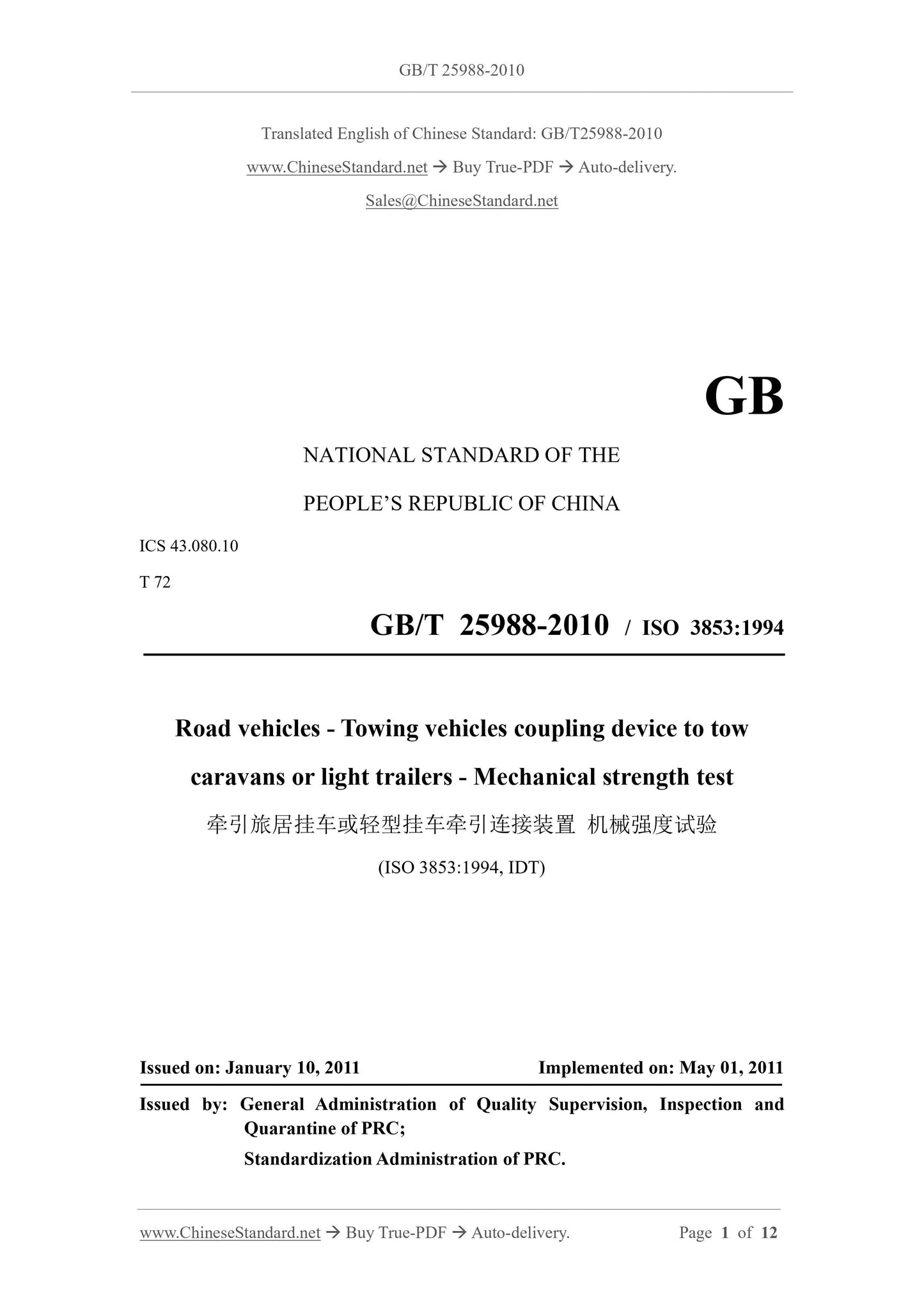
GB/T 25988-2010: Road vehicles -- Towing vehicle coupling device to tow caravans or light trailers -- Mechanical strength test
GB/T 25988-2010
NATIONAL STANDARD OF THE
PEOPLE’S REPUBLIC OF CHINA
ICS 43.080.10
T 72
GB/T 25988-2010 / ISO 3853:1994
Road vehicles - Towing vehicles coupling device to tow
caravans or light trailers - Mechanical strength test
(ISO 3853:1994, IDT)
ISSUED ON: JANUARY 10, 2011
IMPLEMENTED ON: MAY 01, 2011
Issued by: General Administration of Quality Supervision, Inspection and
Quarantine of PRC;
Standardization Administration of PRC.
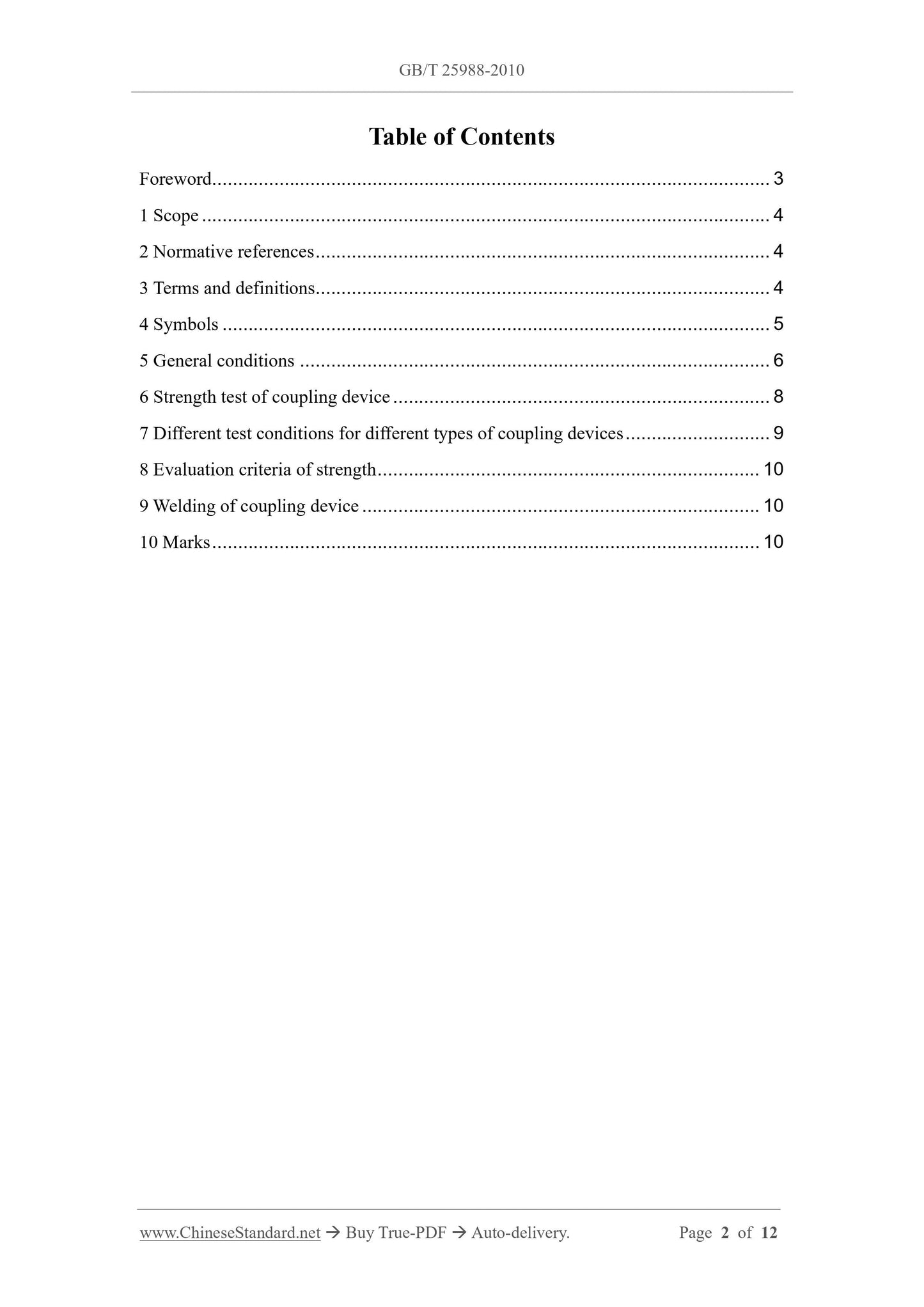
Table of Contents
Foreword ... 3
1 Scope ... 4
2 Normative references ... 4
3 Terms and definitions... 4
4 Symbols ... 5
5 General conditions ... 6
6 Strength test of coupling device ... 8
7 Different test conditions for different types of coupling devices ... 9
8 Evaluation criteria of strength ... 10
9 Welding of coupling device ... 10
10 Marks ... 10
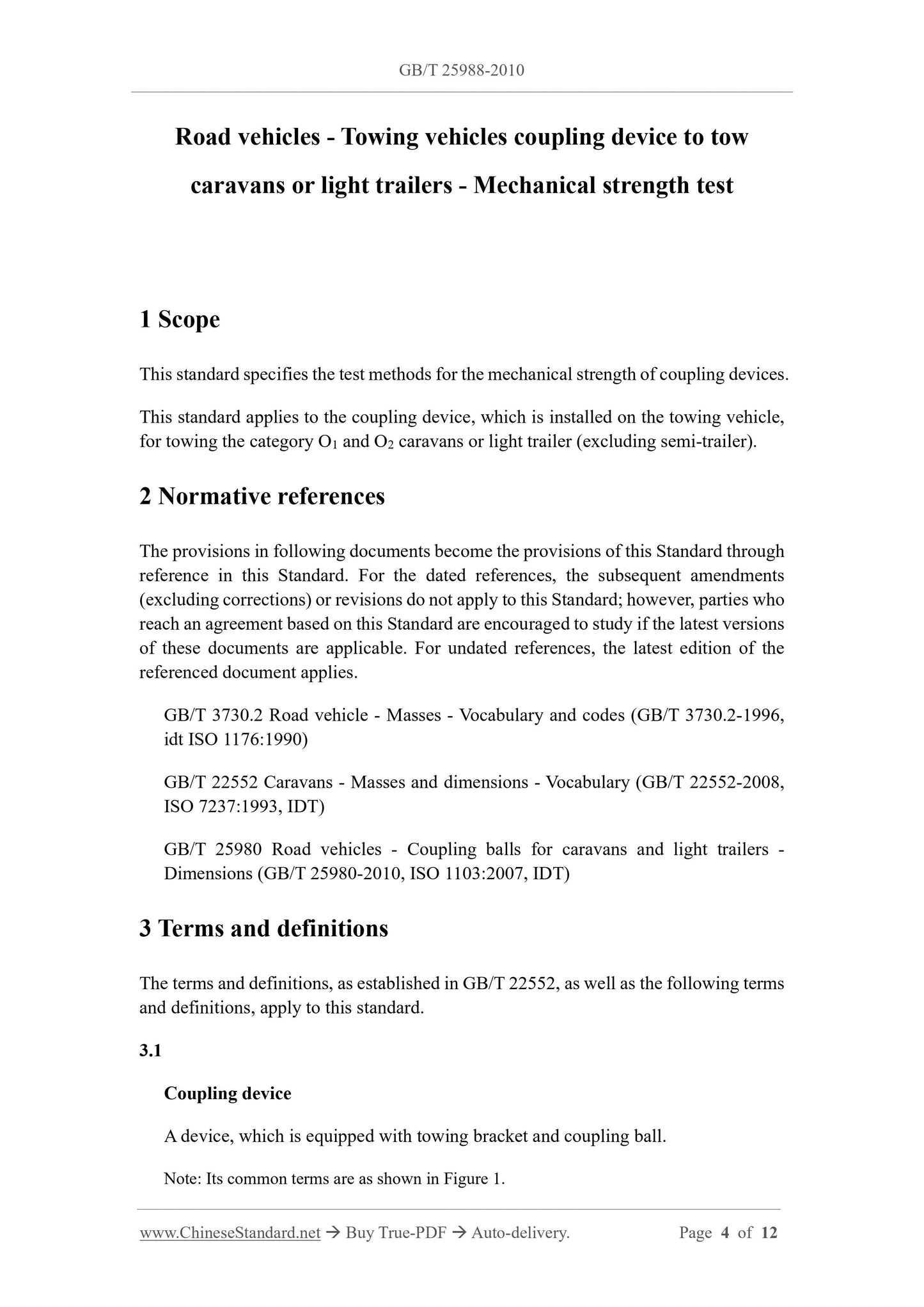
Road vehicles - Towing vehicles coupling device to tow
caravans or light trailers - Mechanical strength test
1 Scope
This standard specifies the test methods for the mechanical strength of coupling devices.
This standard applies to the coupling device, which is installed on the towing vehicle,
for towing the category O1 and O2 caravans or light trailer (excluding semi-trailer).
2 Normative references
The provisions in following documents become the provisions of this Standard through
reference in this Standard. For the dated references, the subsequent amendments
(excluding corrections) or revisions do not apply to this Standard; however, parties who
reach an agreement based on this Standard are encouraged to study if the latest versions
of these documents are applicable. For undated references, the latest edition of the
referenced document applies.
GB/T 3730.2 Road vehicle - Masses - Vocabulary and codes (GB/T 3730.2-1996,
idt ISO 1176:1990)
GB/T 22552 Caravans - Masses and dimensions - Vocabulary (GB/T 22552-2008,
ISO 7237:1993, IDT)
GB/T 25980 Road vehicles - Coupling balls for caravans and light trailers -
Dimensions (GB/T 25980-2010, ISO 1103:2007, IDT)
3 Terms and definitions
The terms and definitions, as established in GB/T 22552, as well as the following terms
and definitions, apply to this standard.
3.1
Coupling device
A device, which is equipped with towing bracket and coupling ball.
Note: Its common terms are as shown in Figure 1.
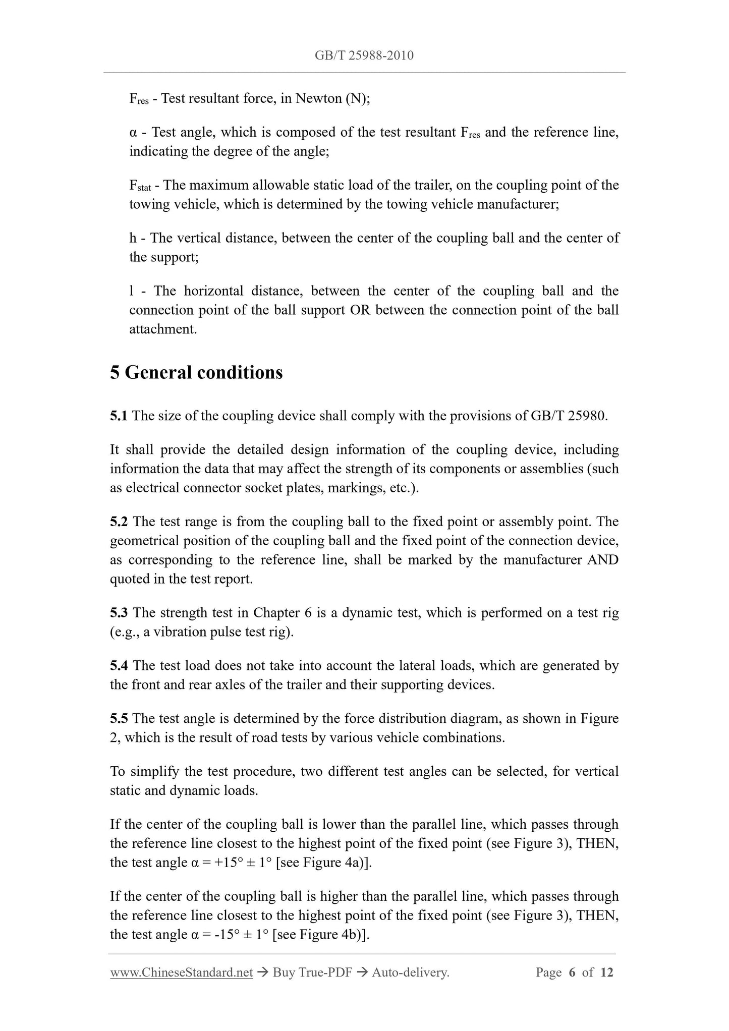
Fres - Test resultant force, in Newton (N);
α - Test angle, which is composed of the test resultant Fres and the reference line,
indicating the degree of the angle;
Fstat - The maximum allowable static load of the trailer, on the coupling point of the
towing vehicle, which is determined by the towing vehicle manufacturer;
h - The vertical distance, between the center of the coupling ball and the center of
the support;
l - The horizontal distance, between the center of the coupling ball and the
connection point of the ball support OR between the connection point of the ball
attachment.
5 General conditions
5.1 The size of the coupling device shall comply with the provisions of GB/T 25980.
It shall provide the detailed design information of the coupling device, including
information the data that may affect the strength of its components or assemblies (such
as electrical connector socket plates, markings, etc.).
5.2 The test range is from the coupling ball to the fixed point or assembly point. The
geometrical position of the coupling ball and the fixed point of the connection device,
as corresponding to the reference line, shall be marked by the manufacturer AND
quoted in the test report.
5.3 The strength test in Chapter 6 is a dynamic test, which is performed on a test rig
(e.g., a vibration pulse test rig).
5.4 The test load does not take into account the lateral loads, which are generated by
the front and rear axles of the trailer and their supporting devices.
5.5 The test angle is determined by the force distribution diagram, as shown in Figure
2, which is the result of road tests by various vehicle combinations.
To simplify the test procedure, two different test angles can be selected, for vertical
static and dynamic loads.
If the center of the coupling ball is lower than the parallel line, which passes through
the reference line closest to the highest point of the fixed point (see Figure 3), THEN,
the test angle α = +15° ± 1° [see Figure 4a)].
If the center of the coupling ball is higher than the parallel line, which passes through
the reference line closest to the highest point of the fixed point (see Figure 3), THEN,
the test angle α = -15° ± 1° [see Figure 4b)].
it shall determine whether the test is appropriate or whether other tests are required, as
necessary.
6 Strength test of coupling device
6.1 Installation on the test bench
The towing bracket shall be connected to the rigid test bench. Its fixed position on the
test bench is the same as the installation position on the towing vehicle, OR has the
same characteristics.
6.2 Fixed points and reference lines
For the installation of the coupling device on the test bench, it shall keep the position
of all fixed points, as relative to the reference line, be consistent with the position of the
fixed point, as relative to the reference line, which is provided by the towing vehicle
manufacturer to the coupling device manufacturer.
If the towing vehicle manufacturer does not provide a fixed point or reference line, the
coupling device manufacturer may choose its own fixed point and reference line, BUT
shall bear the consequences, which are caused by its selected fixed point and reference
line, especially be responsible for the maximum allowable towing mass. In order to
make the position of the coupling ball correct, the towing vehicle manufacturer shall
generally specify the maximum towing mass of the towing vehicle (see code M16 of
GB/T 3730.2).
6.3 Test method
Under the conditions of complying with the requirements of 6.1 and 6.2, the coupling
device, which is installed on the test bench, will be tested, using an alternating load
tensile testing machine. When securing components and applying forces on the test
bench, it shall be ensured that additional movements 1) or other forces 2) are as small
as possible.
The test load shall be applied, at a selected frequency, in an approximate sinusoidal
manner; the frequency shall not exceed 35 Hz and avoid the resonance frequency of the
test device, including the towing device.
The amplitude of the test resultant force Fres is 0.6D ± 3%; the number of cycles is 2 ×
106.
Note: The test device, that connects the force sensor with the ball of the towing device, shall
have a larger mass. The measurement force includes the inertial force, that accelerates the mass.
The applied inertial force can be adjusted, by measuring the acceleration of the coupling ball.
1 For example, it can be realized by relying on the double connection points, which have a spacing of ≥ 300 mm.
2 For example, the force which is generated by large acceleration.
shall be within the following range, namely:
Strength tests for such towing brackets (see Figure 10) shall be in accordance with the
requirements of Chapter 6.
In order to cover all possible positions of the coupling ball, the following two towing
brackets shall be tested:
- Towing bracket, when the ball is at hmax and lmax;
- Towing bracket, when the ball is at hmin and lmin.
7.2.6 The dimensions of the installation surface of the coupling ball support, which is
connected to...
Share
