1
/
of
7
PayPal, credit cards. Download editable-PDF and invoice in 1 second!
GB/T 26990-2023 English PDF (GBT26990-2023)
GB/T 26990-2023 English PDF (GBT26990-2023)
Regular price
$305.00 USD
Regular price
Sale price
$305.00 USD
Unit price
/
per
Shipping calculated at checkout.
Couldn't load pickup availability
Delivery: 3 seconds. Download true-PDF + Invoice.
Get QUOTATION in 1-minute: Click GB/T 26990-2023
Historical versions: GB/T 26990-2023
Preview True-PDF (Reload/Scroll if blank)
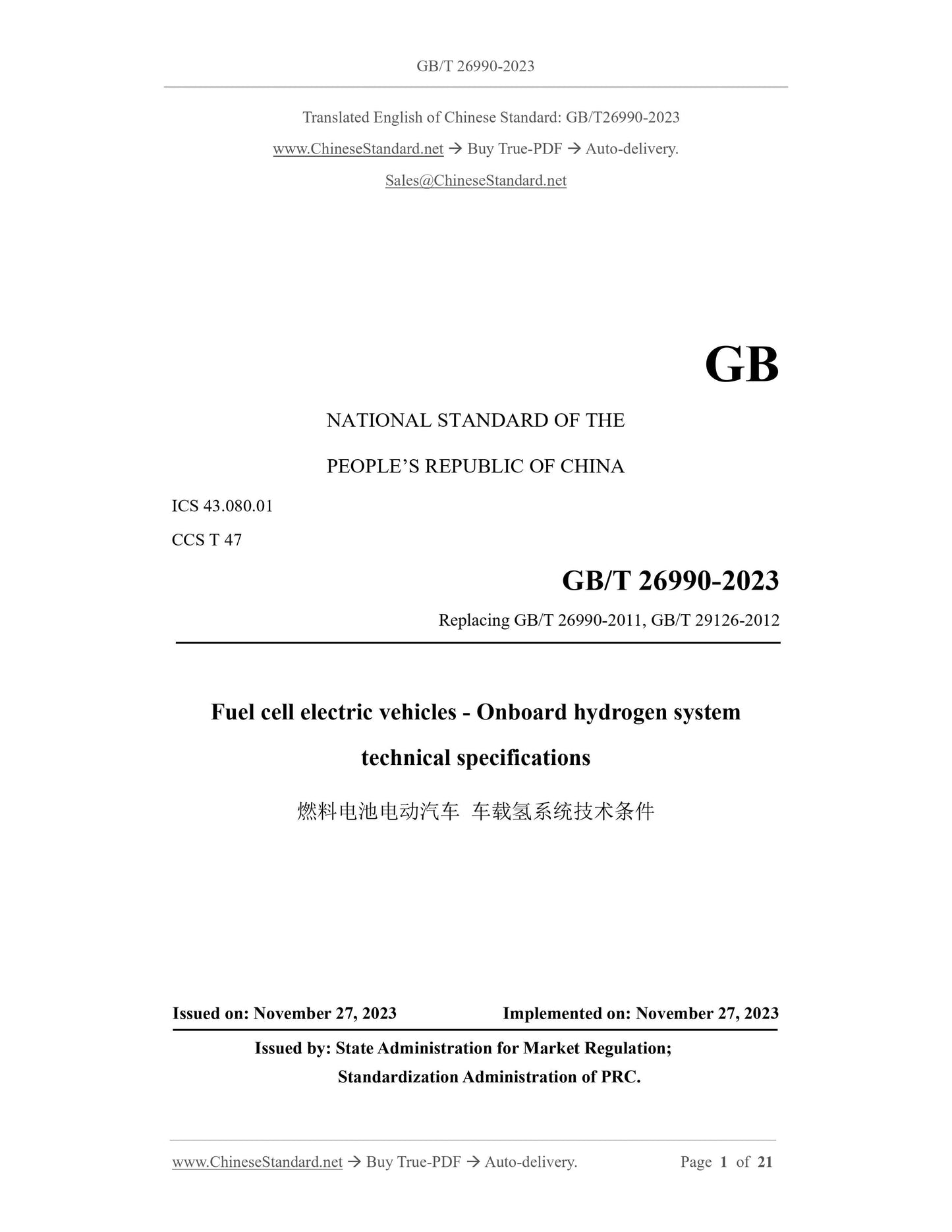
GB/T 26990-2023: Fuel cell electric vehicles -- Onboard hydrogen system technical specifications
GB/T 26990-2023
GB
NATIONAL STANDARD OF THE
PEOPLE’S REPUBLIC OF CHINA
ICS 43.080.01
CCS T 47
Replacing GB/T 26990-2011, GB/T 29126-2012
Fuel cell electric vehicles - Onboard hydrogen system
technical specifications
ISSUED ON: NOVEMBER 27, 2023
IMPLEMENTED ON: NOVEMBER 27, 2023
Issued by: State Administration for Market Regulation;
Standardization Administration of PRC.
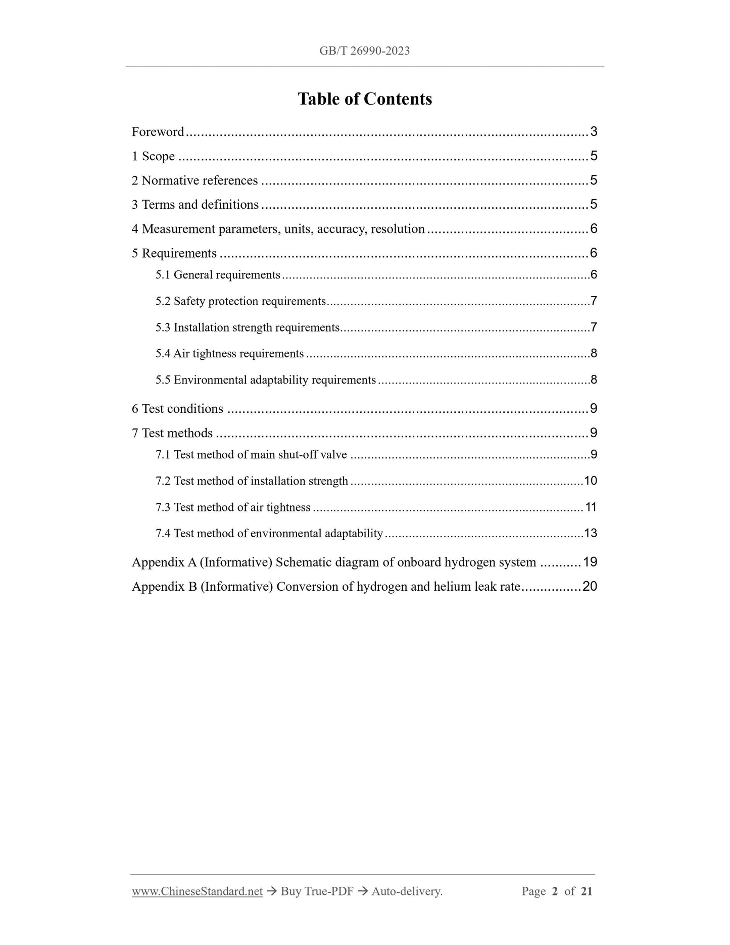
Table of Contents
Foreword ... 3
1 Scope ... 5
2 Normative references ... 5
3 Terms and definitions ... 5
4 Measurement parameters, units, accuracy, resolution ... 6
5 Requirements ... 6
5.1 General requirements ... 6
5.2 Safety protection requirements ... 7
5.3 Installation strength requirements ... 7
5.4 Air tightness requirements ... 8
5.5 Environmental adaptability requirements ... 8
6 Test conditions ... 9
7 Test methods ... 9
7.1 Test method of main shut-off valve ... 9
7.2 Test method of installation strength ... 10
7.3 Test method of air tightness ... 11
7.4 Test method of environmental adaptability ... 13
Appendix A (Informative) Schematic diagram of onboard hydrogen system ... 19
Appendix B (Informative) Conversion of hydrogen and helium leak rate ... 20
Fuel cell electric vehicles - Onboard hydrogen system
technical specifications
1 Scope
This document specifies the technical requirements and test methods for on-board
hydrogen systems of fuel cell electric vehicles.
This document applies to fuel cell electric vehicles, that use compressed gaseous
hydrogen as fuel and have an operating pressure not exceeding 70 MPa, at an ambient
temperature of 15 °C.
2 Normative references
The contents of the following documents constitute essential provisions of this
document through normative references in the text. Among them, for dated reference
documents, only the version corresponding to the date applies to this document; for
undated reference documents, the latest version (including all amendments) applies to
this document.
GB/T 2423.4 Environmental testing for electric and electronic products - Part 2: Test
method - Test Db: Damp heat, cyclic (12 h + 12 h cycle)
GB/T 2423.17 Environmental testing for electric and electronic products - Part 2:
Test method - Test Ka: Salt mist
GB/T 2423.43 Environmental testing for electric and electronic products - Part 2:
Test methods - Mounting of specimens for vibration, impact and similar dynamic
tests
GB/T 2423.56 Environmental testing - Part 2: Test methods - Test Fh: Vibration,
broadband random and guidance
GB/T 24548 Fuel cell electric vehicles - Terminology
GB/T 24549 Fuel cell electric vehicles - Safety requirements
3 Terms and definitions
The terms and definitions as defined in GB/T 24548 and GB/T 24549, as well as the
following terms and definitions, apply to this document.
be complete. The hydrogen cylinders, valves, pipelines, pipeline joints shall not be
damaged. The installation brackets shall have clear anti-loosening marks. The high-
pressure pipeline shall be made of materials with proven good hydrogen compatibility.
If austenitic stainless steel is selected, its nickel content should be greater than 12%.
5.1.2 The on-board hydrogen system shall be manufactured in accordance with the
product drawings and other technical documents approved by the prescribed procedures.
The hydrogenation port, hydrogen storage cylinder, valves and other components shall
comply with relevant standards; a product certificate and batch inspection certificate
shall be provided.
5.1.3 Each hydrogen storage cylinder shall be equipped with a manual stop valve, which
can be used to isolate each hydrogen storage cylinder individually, during
hydrogenation, dehydration or maintenance.
5.2 Safety protection requirements
5.2.1 In order to prevent the pressure downstream of the pressure regulator from
abnormally increasing, the following two methods can be used:
a) Discharge hydrogen gas through safety pressure relief device;
b) Turn off the hydrogen supply upstream of the pressure regulator.
5.2.2 An over-flow protection device or other measures shall be set up to automatically
shut off the hydrogen supply from the hydrogen storage cylinder, when the device that
detects the pressure in the hydrogen storage cylinder or pipeline detects an abnormal
decrease in pressure or an abnormal increase in flow rate. The over-flow protection
valve, if use, shall be installed on or close to the main shut-off valve.
5.2.3 The main shut-off valve, hydrogen storage cylinder's one-way valve, temperature
driven safety pressure relief device (TPRD) shall be installed at the end of the hydrogen
storage cylinder. The operation of the main shut-off valve shall be electric. The test shall
be carried out in accordance with the provisions of 7.1. It shall be ensured that it opens
normally when the power is turned on and closes automatically when the power is
turned off.
5.3 Installation strength requirements
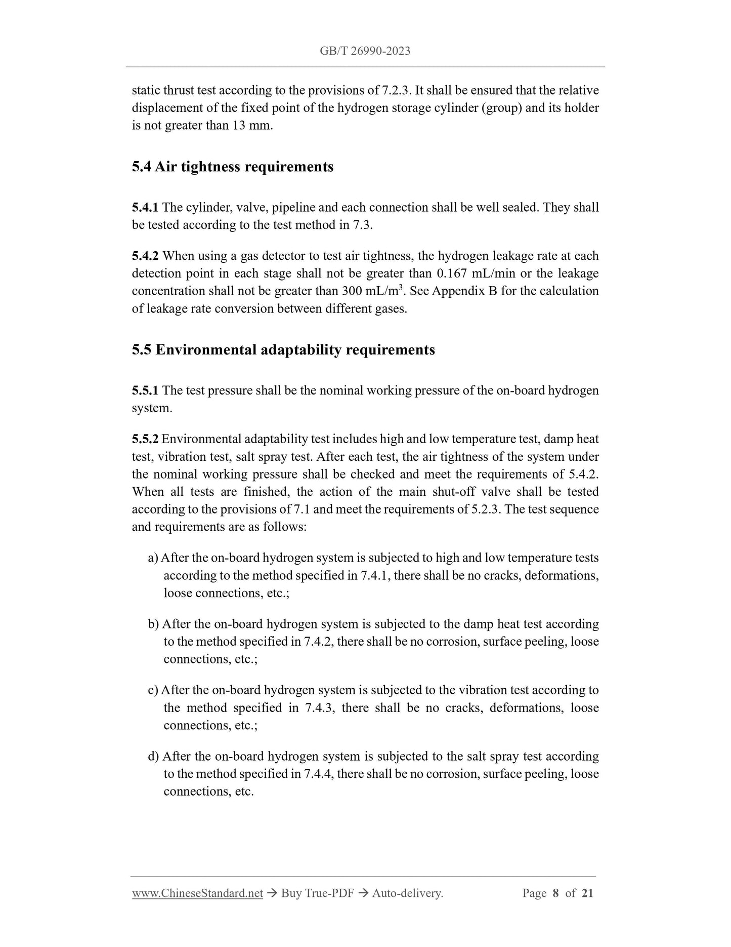
5.3.1 After the hydrogen storage cylinder (group) is installed and tightened, conduct a
dynamic impact test according to the provisions of 7.2.2. It shall be ensured that the
hydrogen storage cylinder (group) is still fixed on the fixed seat; the fastening parts
shall not be deformed, broken, loosen, etc.
5.3.2 After the hydrogen storage cylinder (group) is installed and tightened, conduct a
static thrust test according to the provisions of 7.2.3. It shall be ensured that the relative
displacement of the fixed point of the hydrogen storage cylinder (group) and its holder
is not greater than 13 mm.
5.4 Air tightness requirements
5.4.1 The cylinder, valve, pipeline and each connection shall be well sealed. They shall
be tested according to the test method in 7.3.
5.4.2 When using a gas detector to test air tightness, the hydrogen leakage rate at each
detection point in each stage shall not be greater than 0.167 mL/min or the leakage
concentration shall not be greater than 300 mL/m3. See Appendix B for the calculation
of leakage rate conversion between different gases.
5.5 Environmental adaptability requirements
5.5.1 The test pressure shall be the nominal working pressure of the on-board hydrogen
system.
5.5.2 Environmental adaptability test includes high and low temperature test, damp heat
test, vibration test, salt spray test. After each test, the air tightness of the system under
the nominal working pressure shall be checked and meet the requirements of 5.4.2.
When all tests are finished, the action of the main shut-off valve shall be tested
according to the provisions of 7.1 and meet the requirements of 5.2.3. The test sequence
and requirements are as follows:
a) After the on-board hydrogen system is subjected to high and low temperature tests
according to the method specified in 7.4.1, there shall be no cracks, deformations,
loose connections, etc.;
b) After the on-board hydrogen system is subjected to the damp heat test according
to the method specified in 7.4.2, there shall be no corrosion, surface peeling, loose
connections, etc.;
c) After the on-board hydrogen system is subjected to the vibration test according to
the method specified in 7.4.3, there shall be no cracks, deformations, loose
connections, etc.;
d) After the on-board hydrogen system is subjected to the salt spray test according
to the method specified in 7.4.4, there shall be no corrosion, surface peeling, loose
connections, etc.
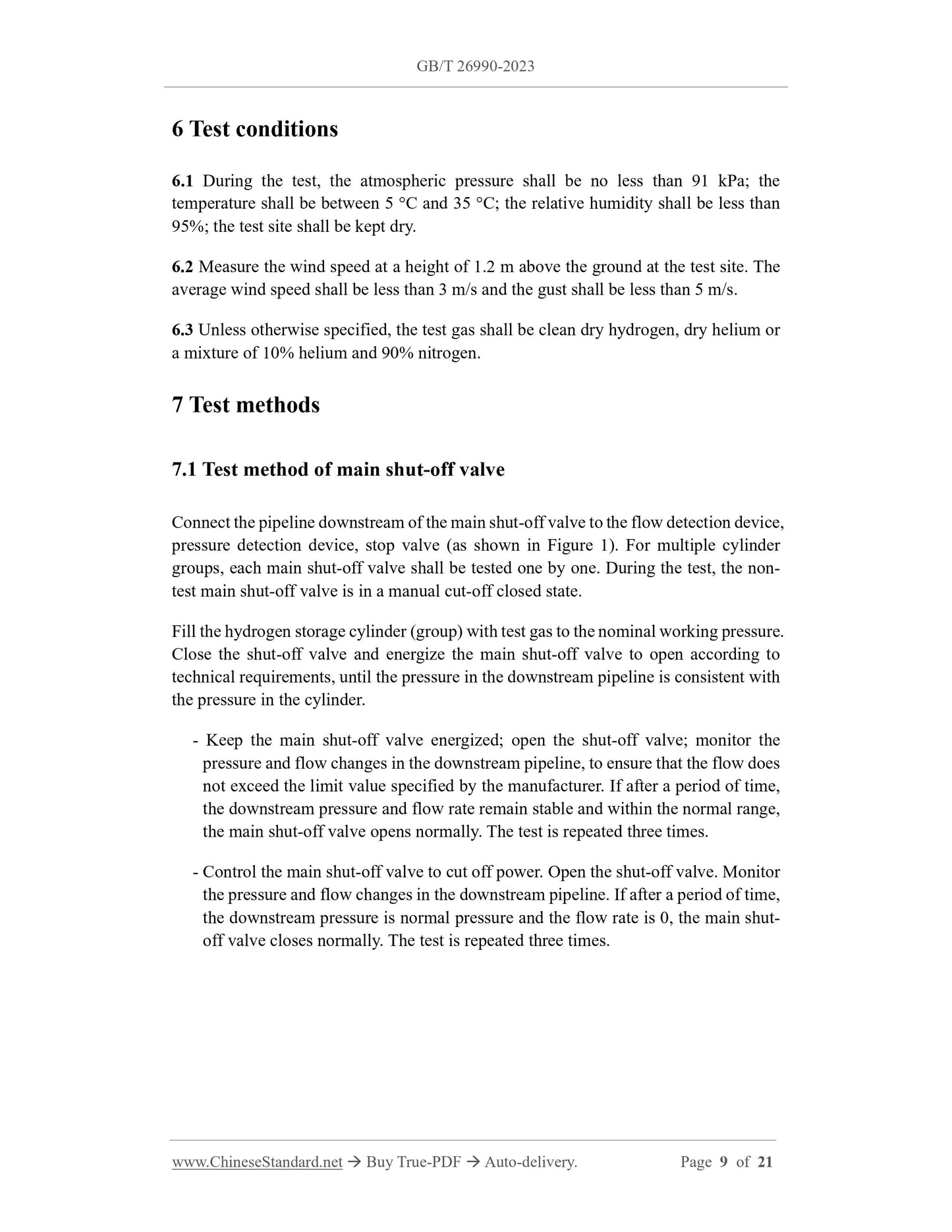
6 Test conditions
6.1 During the test, the atmospheric press...
Share
