1
/
of
11
PayPal, credit cards. Download editable-PDF and invoice in 1 second!
GB/T 31137-2014 English PDF (GB/T31137-2014)
GB/T 31137-2014 English PDF (GB/T31137-2014)
Regular price
$355.00 USD
Regular price
Sale price
$355.00 USD
Unit price
/
per
Shipping calculated at checkout.
Couldn't load pickup availability
Delivery: 3 seconds. Download true-PDF + Invoice.
Get QUOTATION in 1-minute: Click GB/T 31137-2014
Historical versions: GB/T 31137-2014
Preview True-PDF (Reload/Scroll if blank)
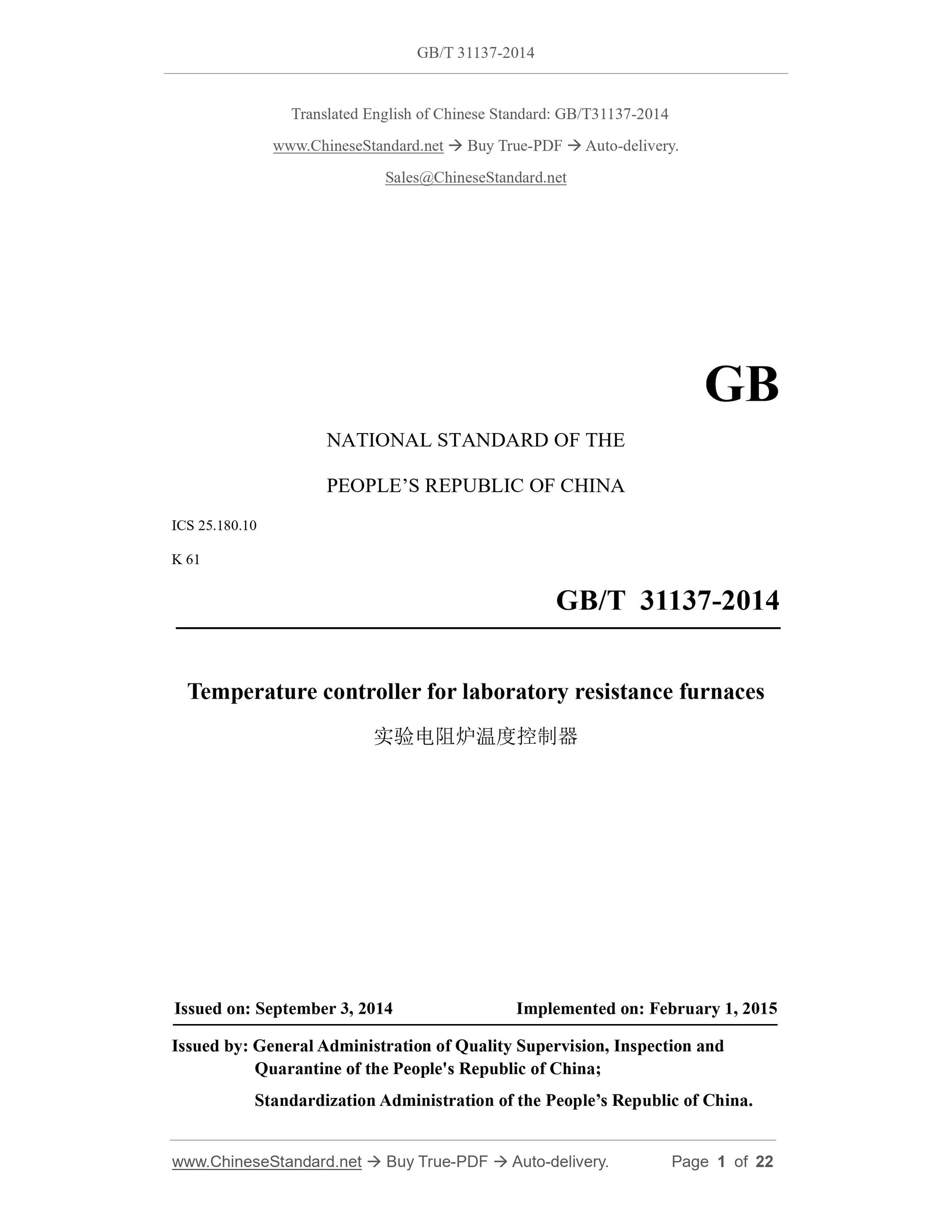
GB/T 31137-2014: Temperature controller for laboratory resistance furnaces
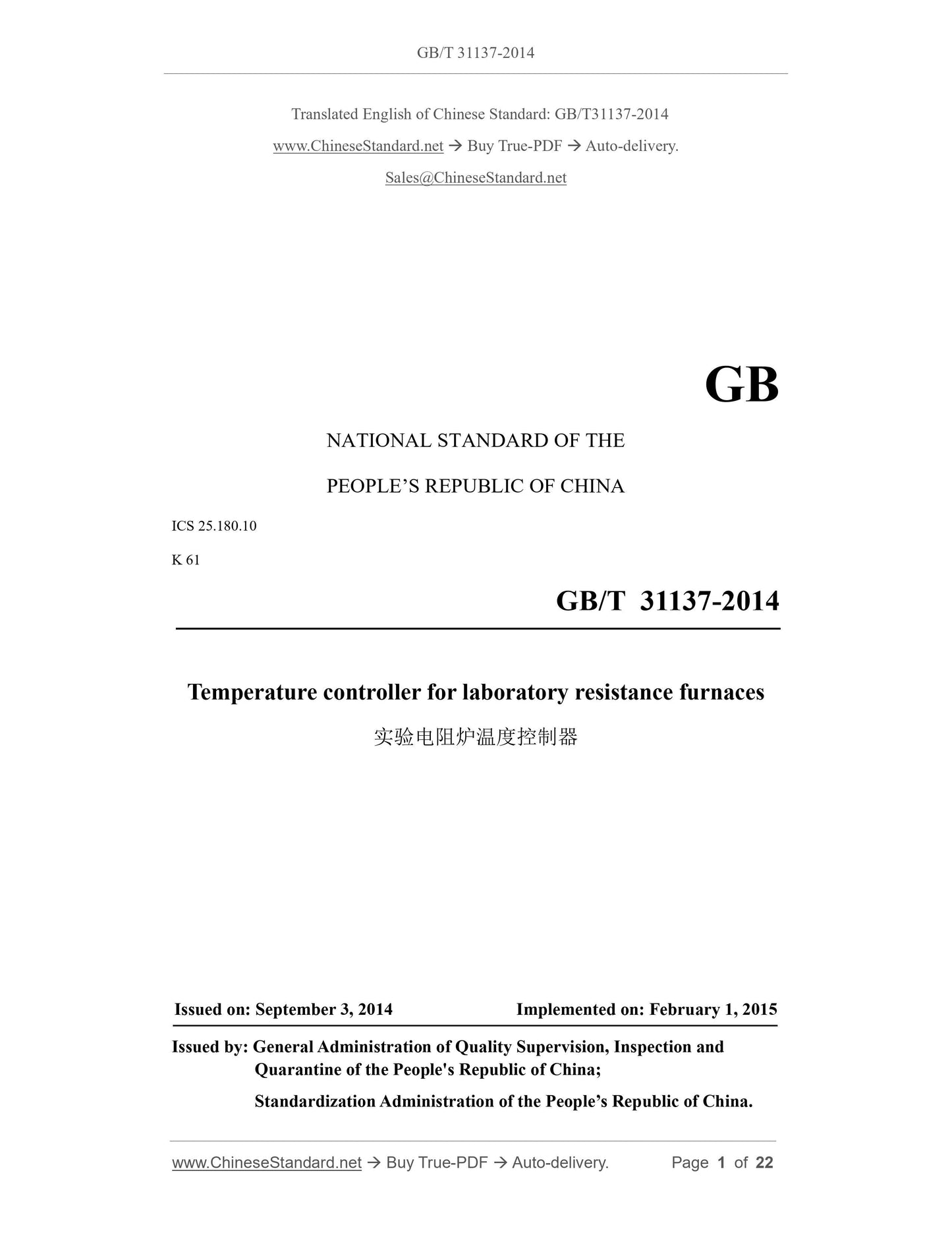
GB/T 31137-2014
GB
NATIONAL STANDARD OF THE
PEOPLE’S REPUBLIC OF CHINA
ICS 25.180.10
K 61
Temperature controller for laboratory resistance furnaces
ISSUED ON: SEPTEMBER 3, 2014
IMPLEMENTED ON: FEBRUARY 1, 2015
Issued by: General Administration of Quality Supervision, Inspection and
Quarantine of the People's Republic of China;
Standardization Administration of the People’s Republic of China.
Table of Contents
Foreword ... 3
1 Scope ... 4
2 Normative references ... 4
3 Terms and definitions ... 5
4 Product classification ... 7
5 Technical requirements ... 10
6 Test methods ... 16
7 Inspection rules and technical classification ... 19
8 Marking, packaging, transportation and storage ... 20
9 Ordering and supply ... 21
Temperature controller for laboratory resistance furnaces
1 Scope
This Standard specifies various requirements for KSB, KSD, KSG, KSJ and KSY series
temperature controllers for laboratory resistance furnaces (hereinafter referred to as
temperature controllers), including product classification, technical requirements, test
methods, inspection rules, technical classification and ordering and supply.
This Standard applies to temperature controllers matched with SX, SK and SG series
laboratory box-type, tube-type and pot-type resistance furnaces.
For other temperature controllers used in laboratory resistance furnaces, this Standard
is for reference only.
2 Normative references
The following referenced documents are indispensable for the application of this
document. For dated references, only the edition cited applies. For undated references,
the latest edition of the referenced document (including any amendments) applies.
GB 1094.11-2007 Power transformers - Part 11: Dry-type transformers
GB/T 2900.23-2008 Electrotechnical terminology - Industrial electroheat
GB/T 4025-2010 Basic and safety principles for man-machine interface, marking
and identification - Coding principles for indicators and actuators
GB/T 4026-2010 Basic and safety principles for man-machine interface, marking
and identification - Identification of equipment terminals and conductor terminations
GB 4208-2008 Degrees of protection provided by enclosure(IP code)
GB 4884-1985 Marking of insulated conductors
GB 7947-2010 Basic and safety principles for man machine interface, marking and
identification - Identification of conductors by colours or alphanumerics
GB/T 10066.1-2004 Test methods for electroheat installations - Part 1: General
GB/T 10067.1-2005 Basic specifications for electroheat installations - Part 1:
General
GB/T 13324-2006 Terminology of heat treatment equipment
h) temperature control accuracy, °C;
i) overall dimensions of the control box (width × depth × height), mm;
j) weight, kg.
5 Technical requirements
5.1 General requirements
The temperature controller shall comply with the relevant provisions of Clause 5 of
GB/T 10067.1-2005. When there is a difference between the provisions of that standard
and this Standard, this Standard shall prevail.
5.2 Supplementary requirements for design and manufacturing
5.2.1 Overall design
The temperature controller for laboratory resistance furnaces refers to the assembly of
software and hardware units such as electrical control components and instruments that
are centrally installed in the temperature control box to achieve heating temperature
measurement, control and recording functions. Because the heating capacity of
laboratory resistance furnaces is small and generally not partitioned, it is different from
the temperature control cabinet for industrial resistance furnaces, and is called a
temperature controller. The temperature controller can be in a separate box or integrated
with the furnace.
The temperature controller can be composed of a box (station) body, a frame and
various electrical components, devices and instruments. The design of the temperature
controller shall be able to ensure that the heat, arc, impact, vibration, magnetic field or
electric field generated by the operation of each electrical component must not interfere
with each other’s normal functioning.
5.2.2 Box (station) body
The temperature controller is generally a separate box (station) body, connected to the
heating body in the furnace through a cable, or it can be directly connected to the
furnace body as a whole. The door or top cover of the temperature controller shall have
hidden buckles or internal pins and shall be able to rotate flexibly. Its opening angle
shall not be less than 90°. Electrical components and instruments shall not be impacted
during the opening process.
Separate holes shall be made on the box (station) body for signal wiring and lead-out
wiring such as thermocouples, actuators, detection switches, etc.
5.2.3 Installation requirements
All components, devices and instruments installed in the temperature controller must
be inspected and qualified before installation. During installation, sufficient distance
for disassembly and repair shall be left according to design requirements. The
contactors and instruments in the temperature controller shall be equipped with
appropriate anti-vibration measures (for example, adding spring washers or rubber pads)
according to the actual working conditions. The wire outlet holes shall be equipped with
insulating outlet rings.
5.2.4 Painting requirements
The paint film surface of the temperature controller must not have defects such as
wrinkles, flow marks, pinholes and blisters.
The paint film on the outer surface of the temperature controller shall be uniform in
color, flat and smooth, and no brush marks, scars, correction marks, obvious mechanical
impurities, spots, etc. that can be seen with the naked eye; the paint film on the inner
surface of the temperature controller shall have a certain anti-corrosion ability.
The outer surface of Class C temperature controller shall be painted or epoxy powder
sprayed, etc. If there are special requirements (see 9.2), they can be agreed upon by
both parties.
5.2.5 Electrical system
5.2.5.1 Power supply
The power supply parameters of the temperature controller are determined according
to the relevant contents in Table 1.
5.2.5.2 Wires
The connecting wires in the temperature controller shall be wired correctly, firmly,
reliably, and arranged neatly and beautifully. The cross-sectional area of the conductor
shall be selected according to the specified carrying capacity. It is generally not less
than 0.75 mm2 for single-core copper insulated wires, and generally not less than 0.5
mm2 for multi-core copper insulated wires.
The connecting wires to each connector shall have copper bare crimp terminals. There
shall be no plugged or soldered transition connections in the middle of each conductor.
The insulated wire markings inside the temperature controller shall comply with the
provisions of GB 4884-1985. The markings shall be printed with a printing machine,
and the writing shall be clear and durable to facilitate use and maintenance.
The color of the wires in the temperature controller shall comply with the provisions of
GB 7947-2010.
5.2.5.3 Terminal blocks
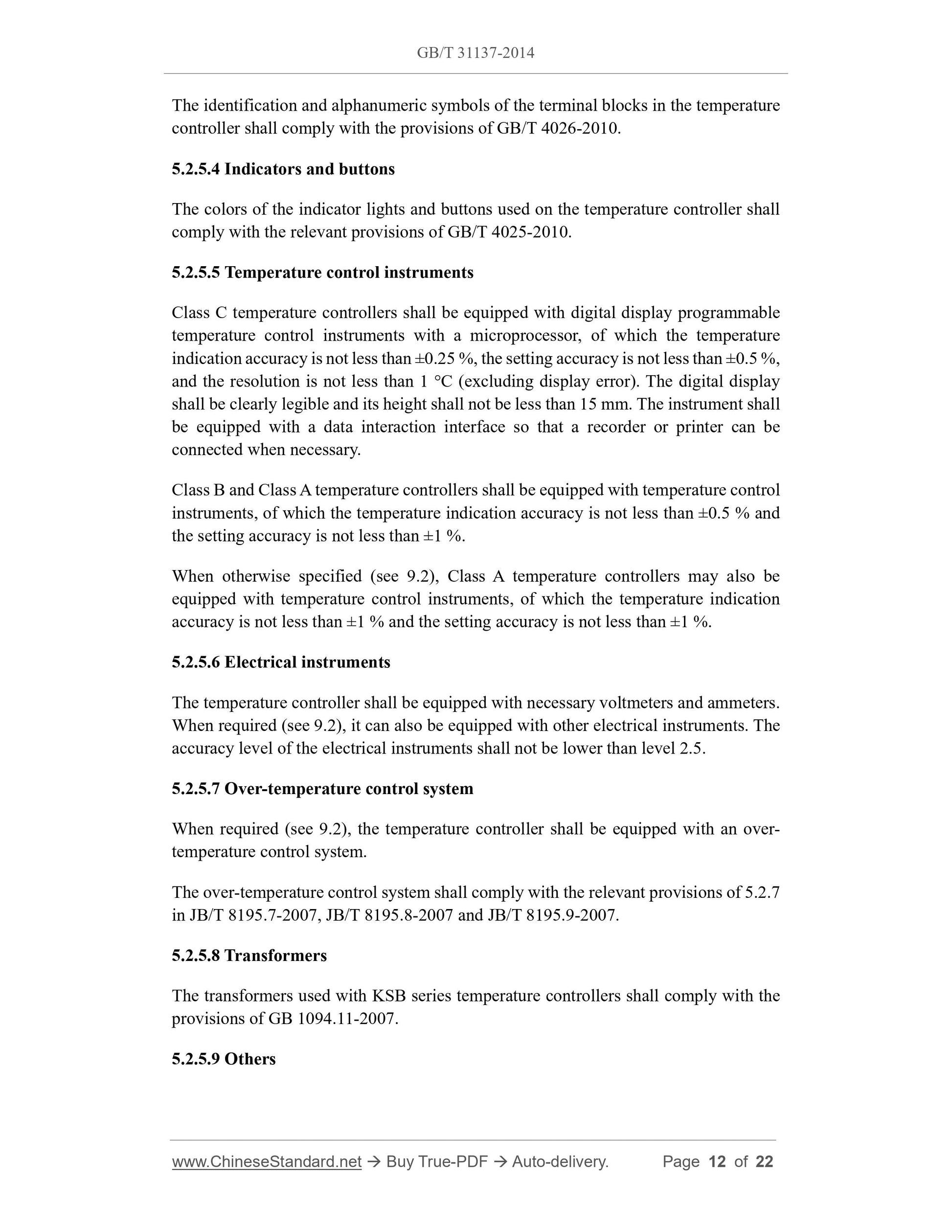
The identification and alphanumeric symbols of the terminal blocks in the temperature
controller shall comply with the provisions of GB/T 4026-2010.
5.2.5.4 Indicators and buttons
The colors of the indicator lights and buttons used on the temperature controller shall
comply with the relevant pr...
Share
