
1
/
of
4
PayPal, credit cards. Download editable-PDF and invoice in 1 second!
GB/T 32325-2015 English PDF (GBT32325-2015)
GB/T 32325-2015 English PDF (GBT32325-2015)
Regular price
$115.00 USD
Regular price
Sale price
$115.00 USD
Unit price
/
per
Shipping calculated at checkout.
Couldn't load pickup availability
Delivery: 3 seconds. Download true-PDF + Invoice.
Get Quotation: Click GB/T 32325-2015 (Self-service in 1-minute)
Historical versions (Master-website): GB/T 32325-2015
Preview True-PDF (Reload/Scroll-down if blank)
GB/T 32325-2015: Rolling bearings - Specifications for vibration (velocity) of deep groove ball bearings
GB/T 32325-2015
Rolling bearings-Specifications for vibration (velocity) of deep groove ball bearings
ICS 21.100.20
J11
National Standards of People's Republic of China
Rolling bearing deep groove ball bearing vibration (speed)
Technical conditions
Rolingbearings-Specificationsforvibration (velocity)
2015-12-31 release
2016-04-01 Implementation
General Administration of Quality Supervision, Inspection and Quarantine of the People's Republic of China
Published by China National Standardization Administration
Foreword
This standard was drafted in accordance with the rules given in GB/T 1.1-2009.
This standard is proposed by China Machinery Industry Federation.
This standard is under the jurisdiction of the National Rolling Bearing Standardization Technical Committee (SAC/TC98).
This standard was drafted. Hangzhou Bearing Test and Research Center Co., Ltd.
Supervision and Inspection Center, Tianma Bearing Group Co., Ltd., Zhejiang Wuzhou Xinchun Group Co., Ltd., Zhejiang Chentong Bearing Co., Ltd.
Zhejiang Times Metrology Technology Co., Ltd.
The main drafters of this standard. Chen Fanghua, Yan Sisi, Li Xianhong, Qian Yaming, Shi Dafang, Shi Zhexi, Zheng Xiaopeng, Chen Jianxin, and Kang Pengfei.
Rolling bearing deep groove ball bearing vibration (speed)
Technical conditions
1 Scope
This standard specifies 0, 2, and 3 series deep groove balls with a nominal outer diameter greater than 10mm to.200mm and an external size in accordance with GB/T 276.
Bearing (hereinafter referred to as bearing) vibration (speed) technical requirements, measurement methods, evaluation methods and inspection rules.
This standard applies to deep groove ball bearings, where the specified V group is the basic requirement for general bearing vibration (speed), V1, V2, V3, V4
And VF3, VF4 groups are suitable for bearings with higher requirements on vibration (speed), of which the VF3 and VF4 groups are only suitable for nominal outside diameters greater than
10mm ~ 100mm bearings.
2 Normative references
The following documents are essential for the application of this document. For dated references, only the dated version applies to this article
Pieces. For undated references, the latest version (including all amendments) applies to this document.
GB/T 276 Rolling bearing deep groove ball bearing dimensions
GB 443 L-AN total loss system oil
GB/T 2828.1 Sampling inspection procedures for counts. Part 1. Batch inspection inspection sampling plan retrieved by acceptance quality limit (AQL)
GB/T 24610.1 Rolling bearing vibration measurement methods-Part 1. Basics
GB/T 24610.2 Methods for measuring vibration of rolling bearings. Part 2. Radial ball bearings with cylindrical bore and cylindrical outer surface
JB/T 2974 Supplementary Provisions for Rolling Bearing Designation
SH0004 Solvent oil for rubber industry
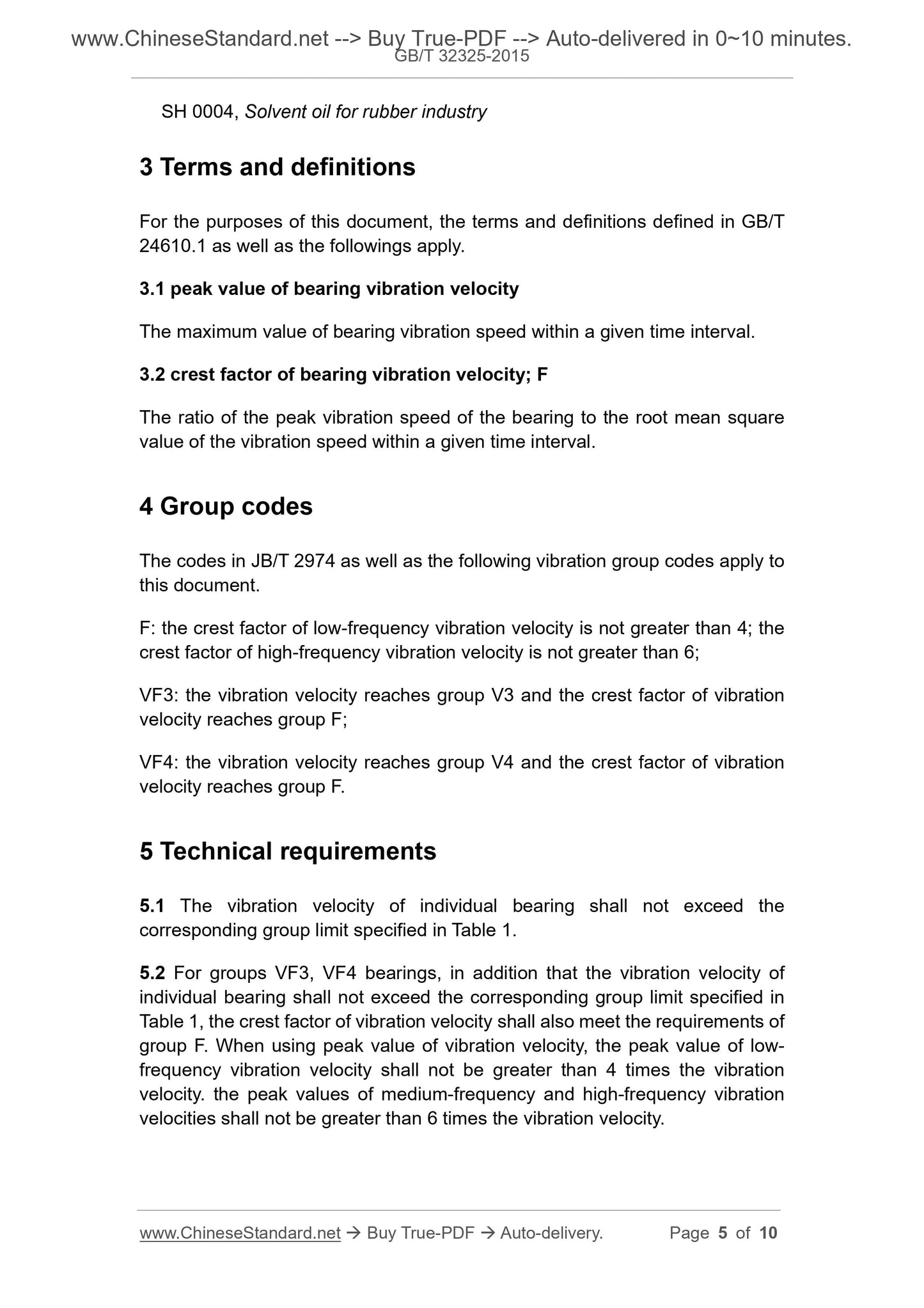
3 terms and definitions
The terms and definitions defined in GB/T 24610.1 and the following terms apply to this document.
3.1
Peak valueofbearingvibrationvelocity
The maximum value of bearing vibration velocity in a given time interval.
3.2
Crest factorofbearingvibrationvelocity
In a given time interval, the ratio of the peak vibration speed of the bearing to the root mean square value of the vibration speed.
4 group codes
The codes in JB/T 2974 and the following vibration group codes apply to this document.
F. Crest factor of low frequency vibration velocity is not greater than 4, Crest factor of medium and high frequency vibration velocity is not greater than 6;
VF3. The vibration speed reaches the V3 group and the vibration velocity crest factor reaches the F group;
VF4. The vibration velocity reaches the V4 group and the vibration velocity crest factor reaches the F group.
5 Technical requirements
5.1 The vibration velocity value of a single bearing should not be greater than the corresponding group limit specified in Table 1.
5.2 For bearings in the VF3 and VF4 groups, except for the vibration speed value should not be greater than the corresponding group limit specified in Table 1, the vibration speed crest factor
Should meet the requirements of Group F. When using the peak value of vibration speed, the peak value of the low frequency vibration speed should not be greater than 4 times the value of the vibration speed.
The peak value of vibration speed should not be more than 6 times the value of vibration speed.
Table 1 Vibration (speed) limits of deep groove ball bearings
Nominal outer diameter D
mm
V V1 V2 V3 V4
> ≤
Low frequency intermediate frequency high frequency low frequency intermediate frequency high frequency low frequency intermediate frequency high frequency low frequency intermediate frequency high frequency low frequency intermediate frequency high frequency
μm/s
10 15 110 60 60 80 40 40 55 28 28 40 18 18 28 12 12
15 20 145 70 70 100 50 50 65 30 30 45 18 18 32 12 12
20 25 185 85 95 120 55 60 80 35 35 52 20 20 35 12 12
25 30 225 100 125 145 65 75 95 40 45 60 25 25 38 15 15
30 40 265 120 170 170 75 100 110 50 65 70 32 35 45 20 20
40 50 310 140 220 195 90 130 125 60 85 80 38 50 50 25 30
50 60 360 160 270 225 105 165 145 70 105 90 45 65 55 30 40
60 70 410 185 320 255 120.200 165 80 125 105 52 80 65 35 50
70 80 460 210 370 285 135 235 185 90 145 120 60 95 75 40 60
80 90 510 240 430 320 155 270 205 100 170 135 68 110 85 45 70
90 100 560 270 490 355 175 310 225 110 195 150 75 125 95 50 80
100 110 610 300 550 390 195 350 250 120 220 165 82 140 105 55 90
110 120 660 330 610 425 215 390 275 130 245 180 90 155 115 60 100
120 130 710 360 670 460 235 430 300 140 270.200 98 170 130 65 110
130 140 760 390 730 500 255 470 330 155 295 220 105 190 145 70 120
140 150 810 420 790 540 275 510 360 170 325 240 115 210 160 75 135
150 160 860 450 850 580 295 550 390 185 355 260 125 230 175 80 150
160 170 920 480 910 620 315 590 420.200 385 280 135 250 190 85 165
170 180 980 510 970 660 335 635 450 215 415 300 145 270 205 90 180
180 190 1040 540 1030 705 355 680 480 230 445 320 155 295 220 100 195
190.200 1100 570 1100 750 375 730 510 250 480 345 165 320 235 110 210
6 Measurement method
6.1 The measurement method shall be in accordance with GB/T 24610.2.
6.2 After the spindle and spindle are combined, the radial and axial circular runout shall not be greater than 5 μm. The measurement method is as specified in Appendix A.
6.3 The basic vibration of the driving device should not exceed the limits specified in Table 2. The measurement method is as specified in Appendix B.
Table 2 Basic vibration limits of the drive unit
Bearing nominal diameter D
mm
Basic vibration
max
> ≤
Low frequency (L) Medium frequency (M) High frequency (H)
μm/s
100.200 15 15 7
7 Evaluation method
7.1 Under the specified measurement conditions, start the measurement after the bearing vibration has reached a steady state for 1 s, and the measurement duration is 2s to 5s.
The measured value should be read at each measuring point in this state.
7.2 Select three measurement points at approximately equal distances in the circumferential direction of the outer cylindrical surface of the outer ring of the bearing.
The large measured value is the vibration value of this bearing in this frequency band.
7.3 In case of dispute, non-prelubricated bearings should be effectively cleaned with NY-120 solvent oil. After the bearings are dried, they must comply with GB 443
The L-AN15 total loss system is measured with oil lubrication. NY-120 solvent oil should be filtered through a filter with a pore size of not more than 0.45 μm.
Other technical requirements are in accordance with the provisions of SH0004; the oil of L-AN15 full loss system should be filtered through a filter with a pore size of no more than 0.8 μm.
8 Inspection rules
8.1 A single bearing is measured according to the method specified in this standard.When the vibration velocity value of any frequency band is greater than the corresponding group limit in Table 1, the bearing is
Non-conforming product; for VF3 and VF4 bearings, when the vibration speed value in any frequency band is greater than the corresponding group limit in Table 1, or the vibration in any frequency band
When the speed crest factor exceeds the requirements of Group F, the bearing is a non-conforming product.
8.2 When sampling the vibration of a batch of bearings, in accordance with GB/T 2828.1, a sampling plan for normal inspection shall be adopted, and general inspection shall be used.
Level II, the AQL value of the receiving quality limit of the vibration velocity is 1.5; the AQL value of the vibration velocity crest factor or the peak value of the vibration velocity is 4.0.
Appendix A
(Normative appendix)
Method for measuring radial circular runout and axial circular runout of mandrel
As shown in Figure A.1, after combining the spindle with the spindle, place the probe of gauge 1 vertically on any part of the mating surface of the spindle and the inner bore of the bearing.
Place the probe of the gauge 2 vertically on any part of the shoulder end face of the mandrel.When the spindle oil supply system is turned on, it is slow and stable at the rear end of the spindle.
Drive the spindle for more than one revolution (the speed is not greater than 10r/min) .The difference between the maximum and minimum indications in meter 1 is the radial circular jump of the spindle.
The difference between the maximum indication and the minimum indication of Test Table 2 is the axial circular runout of the mandrel.
Figure A.1 Schematic diagram of radial and axial runout measurements of a mandrel
Appendix B
(Normative appendix)
Driving device foundation vibration measurement method
As shown in Figure B.1, a rigid foundation vibration measuring rod (cast iron or steel,
(The parallelism of the two end surfaces should not be greater than 0.01mm), so that the sensor head is in contact with the upper end surface of the basic vibration measuring rod, and the contact force is the bearing vibration
Sensor contact force during measurement. Start the spindle and set the electronic measuring instrument range switch (if any) to the minimum position.At this time, the electronic measuring instrument
The low, middle and high frequency bands indicate the basic vibration of the driving device.
Figure B.1 Schematic diagram of basic vibration measurement of the drive unit
Get Quotation: Click GB/T 32325-2015 (Self-service in 1-minute)
Historical versions (Master-website): GB/T 32325-2015
Preview True-PDF (Reload/Scroll-down if blank)
GB/T 32325-2015: Rolling bearings - Specifications for vibration (velocity) of deep groove ball bearings
GB/T 32325-2015
Rolling bearings-Specifications for vibration (velocity) of deep groove ball bearings
ICS 21.100.20
J11
National Standards of People's Republic of China
Rolling bearing deep groove ball bearing vibration (speed)
Technical conditions
Rolingbearings-Specificationsforvibration (velocity)
2015-12-31 release
2016-04-01 Implementation
General Administration of Quality Supervision, Inspection and Quarantine of the People's Republic of China
Published by China National Standardization Administration
Foreword
This standard was drafted in accordance with the rules given in GB/T 1.1-2009.
This standard is proposed by China Machinery Industry Federation.
This standard is under the jurisdiction of the National Rolling Bearing Standardization Technical Committee (SAC/TC98).
This standard was drafted. Hangzhou Bearing Test and Research Center Co., Ltd.
Supervision and Inspection Center, Tianma Bearing Group Co., Ltd., Zhejiang Wuzhou Xinchun Group Co., Ltd., Zhejiang Chentong Bearing Co., Ltd.
Zhejiang Times Metrology Technology Co., Ltd.
The main drafters of this standard. Chen Fanghua, Yan Sisi, Li Xianhong, Qian Yaming, Shi Dafang, Shi Zhexi, Zheng Xiaopeng, Chen Jianxin, and Kang Pengfei.
Rolling bearing deep groove ball bearing vibration (speed)
Technical conditions
1 Scope
This standard specifies 0, 2, and 3 series deep groove balls with a nominal outer diameter greater than 10mm to.200mm and an external size in accordance with GB/T 276.
Bearing (hereinafter referred to as bearing) vibration (speed) technical requirements, measurement methods, evaluation methods and inspection rules.
This standard applies to deep groove ball bearings, where the specified V group is the basic requirement for general bearing vibration (speed), V1, V2, V3, V4
And VF3, VF4 groups are suitable for bearings with higher requirements on vibration (speed), of which the VF3 and VF4 groups are only suitable for nominal outside diameters greater than
10mm ~ 100mm bearings.
2 Normative references
The following documents are essential for the application of this document. For dated references, only the dated version applies to this article
Pieces. For undated references, the latest version (including all amendments) applies to this document.
GB/T 276 Rolling bearing deep groove ball bearing dimensions
GB 443 L-AN total loss system oil
GB/T 2828.1 Sampling inspection procedures for counts. Part 1. Batch inspection inspection sampling plan retrieved by acceptance quality limit (AQL)
GB/T 24610.1 Rolling bearing vibration measurement methods-Part 1. Basics
GB/T 24610.2 Methods for measuring vibration of rolling bearings. Part 2. Radial ball bearings with cylindrical bore and cylindrical outer surface
JB/T 2974 Supplementary Provisions for Rolling Bearing Designation
SH0004 Solvent oil for rubber industry
3 terms and definitions
The terms and definitions defined in GB/T 24610.1 and the following terms apply to this document.
3.1
Peak valueofbearingvibrationvelocity
The maximum value of bearing vibration velocity in a given time interval.
3.2
Crest factorofbearingvibrationvelocity
In a given time interval, the ratio of the peak vibration speed of the bearing to the root mean square value of the vibration speed.
4 group codes
The codes in JB/T 2974 and the following vibration group codes apply to this document.
F. Crest factor of low frequency vibration velocity is not greater than 4, Crest factor of medium and high frequency vibration velocity is not greater than 6;
VF3. The vibration speed reaches the V3 group and the vibration velocity crest factor reaches the F group;
VF4. The vibration velocity reaches the V4 group and the vibration velocity crest factor reaches the F group.
5 Technical requirements
5.1 The vibration velocity value of a single bearing should not be greater than the corresponding group limit specified in Table 1.
5.2 For bearings in the VF3 and VF4 groups, except for the vibration speed value should not be greater than the corresponding group limit specified in Table 1, the vibration speed crest factor
Should meet the requirements of Group F. When using the peak value of vibration speed, the peak value of the low frequency vibration speed should not be greater than 4 times the value of the vibration speed.
The peak value of vibration speed should not be more than 6 times the value of vibration speed.
Table 1 Vibration (speed) limits of deep groove ball bearings
Nominal outer diameter D
mm
V V1 V2 V3 V4
> ≤
Low frequency intermediate frequency high frequency low frequency intermediate frequency high frequency low frequency intermediate frequency high frequency low frequency intermediate frequency high frequency low frequency intermediate frequency high frequency
μm/s
10 15 110 60 60 80 40 40 55 28 28 40 18 18 28 12 12
15 20 145 70 70 100 50 50 65 30 30 45 18 18 32 12 12
20 25 185 85 95 120 55 60 80 35 35 52 20 20 35 12 12
25 30 225 100 125 145 65 75 95 40 45 60 25 25 38 15 15
30 40 265 120 170 170 75 100 110 50 65 70 32 35 45 20 20
40 50 310 140 220 195 90 130 125 60 85 80 38 50 50 25 30
50 60 360 160 270 225 105 165 145 70 105 90 45 65 55 30 40
60 70 410 185 320 255 120.200 165 80 125 105 52 80 65 35 50
70 80 460 210 370 285 135 235 185 90 145 120 60 95 75 40 60
80 90 510 240 430 320 155 270 205 100 170 135 68 110 85 45 70
90 100 560 270 490 355 175 310 225 110 195 150 75 125 95 50 80
100 110 610 300 550 390 195 350 250 120 220 165 82 140 105 55 90
110 120 660 330 610 425 215 390 275 130 245 180 90 155 115 60 100
120 130 710 360 670 460 235 430 300 140 270.200 98 170 130 65 110
130 140 760 390 730 500 255 470 330 155 295 220 105 190 145 70 120
140 150 810 420 790 540 275 510 360 170 325 240 115 210 160 75 135
150 160 860 450 850 580 295 550 390 185 355 260 125 230 175 80 150
160 170 920 480 910 620 315 590 420.200 385 280 135 250 190 85 165
170 180 980 510 970 660 335 635 450 215 415 300 145 270 205 90 180
180 190 1040 540 1030 705 355 680 480 230 445 320 155 295 220 100 195
190.200 1100 570 1100 750 375 730 510 250 480 345 165 320 235 110 210
6 Measurement method
6.1 The measurement method shall be in accordance with GB/T 24610.2.
6.2 After the spindle and spindle are combined, the radial and axial circular runout shall not be greater than 5 μm. The measurement method is as specified in Appendix A.
6.3 The basic vibration of the driving device should not exceed the limits specified in Table 2. The measurement method is as specified in Appendix B.
Table 2 Basic vibration limits of the drive unit
Bearing nominal diameter D
mm
Basic vibration
max
> ≤
Low frequency (L) Medium frequency (M) High frequency (H)
μm/s
100.200 15 15 7
7 Evaluation method
7.1 Under the specified measurement conditions, start the measurement after the bearing vibration has reached a steady state for 1 s, and the measurement duration is 2s to 5s.
The measured value should be read at each measuring point in this state.
7.2 Select three measurement points at approximately equal distances in the circumferential direction of the outer cylindrical surface of the outer ring of the bearing.
The large measured value is the vibration value of this bearing in this frequency band.
7.3 In case of dispute, non-prelubricated bearings should be effectively cleaned with NY-120 solvent oil. After the bearings are dried, they must comply with GB 443
The L-AN15 total loss system is measured with oil lubrication. NY-120 solvent oil should be filtered through a filter with a pore size of not more than 0.45 μm.
Other technical requirements are in accordance with the provisions of SH0004; the oil of L-AN15 full loss system should be filtered through a filter with a pore size of no more than 0.8 μm.
8 Inspection rules
8.1 A single bearing is measured according to the method specified in this standard.When the vibration velocity value of any frequency band is greater than the corresponding group limit in Table 1, the bearing is
Non-conforming product; for VF3 and VF4 bearings, when the vibration speed value in any frequency band is greater than the corresponding group limit in Table 1, or the vibration in any frequency band
When the speed crest factor exceeds the requirements of Group F, the bearing is a non-conforming product.
8.2 When sampling the vibration of a batch of bearings, in accordance with GB/T 2828.1, a sampling plan for normal inspection shall be adopted, and general inspection shall be used.
Level II, the AQL value of the receiving quality limit of the vibration velocity is 1.5; the AQL value of the vibration velocity crest factor or the peak value of the vibration velocity is 4.0.
Appendix A
(Normative appendix)
Method for measuring radial circular runout and axial circular runout of mandrel
As shown in Figure A.1, after combining the spindle with the spindle, place the probe of gauge 1 vertically on any part of the mating surface of the spindle and the inner bore of the bearing.
Place the probe of the gauge 2 vertically on any part of the shoulder end face of the mandrel.When the spindle oil supply system is turned on, it is slow and stable at the rear end of the spindle.
Drive the spindle for more than one revolution (the speed is not greater than 10r/min) .The difference between the maximum and minimum indications in meter 1 is the radial circular jump of the spindle.
The difference between the maximum indication and the minimum indication of Test Table 2 is the axial circular runout of the mandrel.
Figure A.1 Schematic diagram of radial and axial runout measurements of a mandrel
Appendix B
(Normative appendix)
Driving device foundation vibration measurement method
As shown in Figure B.1, a rigid foundation vibration measuring rod (cast iron or steel,
(The parallelism of the two end surfaces should not be greater than 0.01mm), so that the sensor head is in contact with the upper end surface of the basic vibration measuring rod, and the contact force is the bearing vibration
Sensor contact force during measurement. Start the spindle and set the electronic measuring instrument range switch (if any) to the minimum position.At this time, the electronic measuring instrument
The low, middle and high frequency bands indicate the basic vibration of the driving device.
Figure B.1 Schematic diagram of basic vibration measurement of the drive unit
Share