1
/
of
5
PayPal, credit cards. Download editable-PDF and invoice in 1 second!
GB/T 324-2008 English PDF (GBT324-2008)
GB/T 324-2008 English PDF (GBT324-2008)
Regular price
$70.00 USD
Regular price
Sale price
$70.00 USD
Unit price
/
per
Shipping calculated at checkout.
Couldn't load pickup availability
Delivery: 3 seconds. Download true-PDF + Invoice.
Get Quotation: Click GB/T 324-2008 (Self-service in 1-minute)
Historical versions (Master-website): GB/T 324-2008
Preview True-PDF (Reload/Scroll-down if blank)
GB/T 324-2008: Weld symbolic representation on drawings
GB/T 324-2008
Weld symbolic representation on drawings
ICS 25.160.01
J33
National Standards of People's Republic of China
Replace GB/T 324-1988
Weld symbol notation
(ISO 2553.1992, Welded, brazedandsolderedjoints-Symbolic
Representationondrawings, MOD)
Released on.2008-06-26
2009-01-01 implementation
General Administration of Quality Supervision, Inspection and Quarantine of the People's Republic of China
China National Standardization Administration issued
Foreword
This standard is modified to use ISO 2553.1992 "symbol representation of the welding, brazing and soldering joints on the drawings" (English version).
The main differences between this standard and ISO 2553.1992 are as follows.
--- Removed the preface to international standards;
--- ISO 123.1982, ISO 544.1989, ISO 1302.1978, ISO 2560.1973 were removed from the normative references.
ISO 3098-1.1974, ISO 3581.1976, ISO 8167.1989, added GB/T 12212-1990;
--- Added several supplementary symbols;
--- Dimensioning method has been refined;
--- Removed some examples from international standards.
This standard replaces GB/T 324-1988 "welding symbol notation".
The main changes in this standard compared with GB/T 324-1988 are as follows.
--- The scope of application is extended to the brazed joint;
--- Added 7 basic symbols;
--- The original "auxiliary symbols" and "supplemental symbols" were merged into "supplemental symbols", and a smooth transition symbol was added to the original lining
The mat is subdivided into permanent liners and temporary liners;
--- The example section has been adjusted according to practical and concise principles.
Appendix A of this standard is an informative annex.
This standard is proposed and managed by the National Welding Standardization Technical Committee.
This standard was drafted. Harbin Welding Research Institute, Beijing Electric Power Construction Company, Lanzhou Lanshi Machinery Equipment Co., Ltd.
The main drafters of this standard. Park Dong-Guang, Ren Yongning, Lei Wanqing.
The previous versions of the standards replaced by this standard are.
---GB 324-1964, GB/T 324-1980, GB/T 324-1988.
Weld symbol notation
1 range
This standard specifies the rules for the representation of weld symbols.
This standard applies to the symbolic labeling of welded joints.
2 Normative references
The terms in the following documents become the terms of this standard by reference to this standard. All dated references, followed by all
Modifications (not including errata content) or revisions do not apply to this standard, however, parties to agreements based on this standard are encouraged to study
Is it possible to use the latest version of these files? For undated references, the latest edition applies to this standard.
GB/T 5185 welding and related process code (GB/T 5185-2005, ISO 4063.1998, IDT)
GB/T 12212 Technical drawing weld symbol size, proportion and simplified representation
GB/T 16672 Definition of dip angle and corner of weld working position (GB/T 16672-1996, idt ISO 6947.1993)
Guide for quality classification of arc welding joint defects of GB/T 19418 steel (GB/T 19418-2003, ISO 5817.1992, IDT)
3 General
Weld symbols are recommended when welds or joints are required on technical drawings or documents. If necessary, general technical system can also be used.
Diagram method representation.
The weld symbol should clearly state the information to be described and does not add more annotations to the pattern.
Complete weld symbols include basic symbols, leader lines, supplementary symbols, size symbols, and data. For simplification, mark the weld on the pattern
The basic symbols and guide lines are usually used for the seams, and other contents are generally specified in the relevant documents (such as welding procedure regulations).
Refer to the relevant provisions of GB/T 12212 for the proportion, size and location of the symbols.
4 symbol
4.1 Basic symbols
The basic symbols indicate the basic form or characteristics of the weld cross section. See Table 1 for details and Appendix A for application.
Table 1 Basic symbols
Serial number name schematic symbol
1 crimping seam (complete curling of the crimp)
2 I-shaped weld
3 V-shaped weld
4 single-sided V-shaped weld
Table 1 (continued)
Serial number name schematic symbol
5 with blunt V-shaped weld
6 single-sided V-shaped weld with blunt edge
7 U-shaped weld with blunt edge
8 with a blunt edge J-shaped weld
9 back cover weld
10 fillet weld
11 plug weld or groove weld
12 point weld
13 seam weld
14 steep V-shaped weld
15 steep single V-weld weld
16 end weld
Table 1 (continued)
Serial number name schematic symbol
17 weld seam
18 flat connection (brazing)
19 beveled connection (brazing)
20 folding connection (brazing)
4.2 Combination of basic symbols
When marking double-sided welds or joints, the basic symbols can be combined, as shown in Table 2.
Table 2 Combination of basic symbols
Serial number name schematic symbol
Double-sided V-shaped weld
(X weld)
Double-sided single V-shaped weld
(K weld)
3 double-sided V-shaped weld with blunt edges
4 double-sided single V-shaped weld with blunt edges
5 double-sided U-shaped weld
4.3 supplementary symbols
Supplemental symbols are used to supplement certain features related to welds or joints (such as surface shape, gasket, weld distribution, weld location, etc.).
See Table 3 for additional symbols.
Table 3 Supplementary symbols
Serial number name symbol description
1 Plane weld surface is usually processed and flattened
2 concave surface of the weld surface
3 convex weld surface convex
4 smooth transition weld toe transition smooth
5 Permanent padding is permanently retained
6 Temporary padding is removed after welding is completed
7 three-sided welds with welds on three sides
8 surrounding welds
Welds welded along the periphery of the workpiece
The marked position is the intersection of the baseline and the arrow line
9 Welds welded on site in the field
10 tail can indicate the required information
5 Basic symbols and guidelines for positional requirements
5.1 Basic requirements
In the weld symbol, the basic symbols and guidelines are the basic elements. The exact position of the weld is usually between the basic symbol and the guide line
Relative position is determined, the specific location includes.
---The position of the arrow line;
---The position of the baseline;
--- The location of the basic symbol.
5.2 Guideline
The leader line consists of an arrow line and a baseline (solid and dashed lines), as shown in Figure 1.
Figure 1 leader line
5.2.1 Arrow line
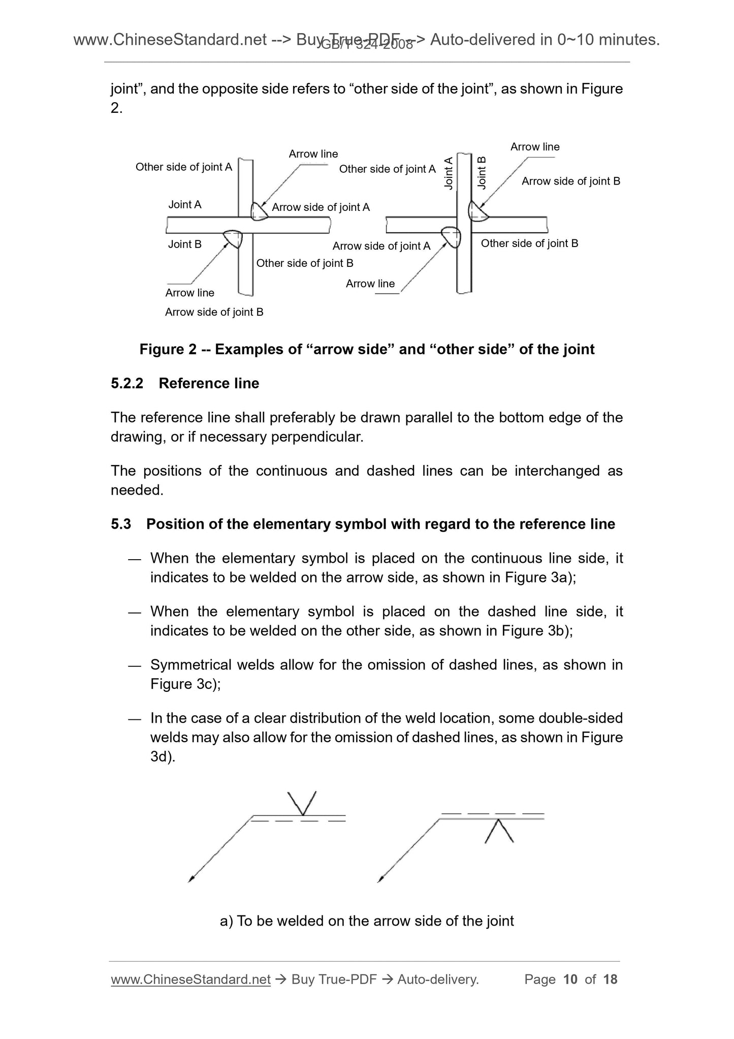
The side of the joint directly pointed by the arrow is the "arrow side of the joint", and the opposite side is the "non-arrow side of the joint", see Figure 2.
Figure 2 Example of the "arrow side" and "non-arrow side" of the connector
5.2.2 Baseline
The reference line should generally be parallel to the bottom edge of the pattern and, if necessary, perpendicular to the bottom edge.
The positions of the solid and dashed lines can be interchanged as needed.
5.3 Relative position of the basic symbol and the baseline
--- The basic symbol on the solid side indicates that the weld is on the arrow side, see Figure 3a);
--- The basic symbol on the side of the dotted line indicates that the weld is on the non-arrow side, see Figure 3b);
--- Symmetrical welds allow the omission of dashed lines, see Figure 3c);
--- In the case of clear weld placement, some double-sided welds can also omit the dotted line, see Figure 3d).
a) The weld is on the arrow side of the joint
b) the weld is on the non-arrow side of the joint
c) symmetric weld d) double-sided weld
Figure 3 Relative position of the basic symbol and the baseline
6 size and labeling
6.1 General requirements
If necessary, you can dimension the weld symbol. See Table 4 for the size symbols.
Table 4 size symbols
Symbol name schematic
δ workpiece thickness
坡 groove angle
β groove face angle
Root gap
R root radius
H Groove depth
S Weld thickness
Symbol name schematic
犮weld width
K solder fillet size
Spot welding. nugget diameter
Plug welding. aperture
Number of weld segments
N the same number of welds
6.2 Labeling rules
See Figure 4 for the method of dimensioning.
--- Horizontal dimension on the left side of the basic symbol;
---The vertical dimension is marked on the right side of the basic symbol;
---The groove angle, the groove face angle, and the root gap are marked on the upper or lower side of the basic symbol;
---The same number of welds is marked at the end;
--- When the size is more difficult to distinguish, you can mark the corresponding size symbol before the size data.
When the direction of the arrow line changes, the above rules do not change.
Figure 4 Dimensioning method
6.3 Other regulations on dimensions
Make sure that the dimensions of the weld location are not marked in the weld symbol and should be marked on the drawing.
No dimensioning on the right side of the basic symbol and no other instructions means that the weld is connected throughout the length of the workpiece.
Continued.
No dimensioning on the left side of the basic symbol and no other instructions means that the butt weld should be completely penetrated.
When the plug weld or groove weld has a beveled edge, the size of the bottom should be marked.
Appendix A
(informative appendix)
Application example of weld symbol
A. 1 Application of basic symbols
Table A. An example of the application of the basic symbols is given in 1.
Table A. 1 Application example of basic symbols
Serial number symbol schematic label example note
A. 2 Supplementary symbol application example
A. 2.1 Table A. 2 and Table A. 3 gives the application of the supplementary symbols and an example of the labeling.
Table A. 2 Supplementary symbol application example
Serial number name schematic symbol
1 flush V-shaped weld
2 raised double-sided V-shaped weld
3 concave fillet welds
4 flush V-shaped welds and backsea welds
5 smooth transition welds on the surface
Table A. 3 Example of labeling of supplementary symbols
Serial number symbol schematic label example note
A. 2.2 Other supplementary instructions
A. 2.2.1 Surrounding welds
When the weld is around the periphery of the workpiece, a circular symbol can be used, as shown in Figure A. 1 is shown.
Figure A. 1 Labeling of surrounding welds
A. 2.2.2 On-site weld
Use a small flag to indicate a field or field weld, as shown in Figure A. 2.
Figure A. 2 representation of the weld on site
A. 2.2.3 Labeling of welding methods
If necessary, the welding method code can be marked at the end, as shown in Figure A. 3.
Figure A. 3 tail marking of the welding method
A. 2.2.4 Order of the content of the tail label
When there are many contents to be marked at the end, they can be arranged in the following order.
---The same number of welds;
--- Welding method code (according to GB/T 5185);
---Lack of quality level (according to GB/T 19418);
--- Welding position (according to GB/T 16672);
---Welding materials (such as in accordance with relevant welding material standards);
---other.
Each payment is separated by a slash "/".
In order to simplify the drawing, you can also include the above content in a file, and use the closed tail to give the number of the file (such as
WPS number or form number, etc.), see Figure A. 4.
Figure A. 4 closed tail example
A. 3 dimensioning example
Table A. 4 gives an example of the dimensioning.
Table A. 4 Example of dimensioning
Serial number name schematic size symbol labeling method
1 butt weld S. effective thickness of weld
continuous
Fillet weld K
. soldering foot size
Intermittent
Fillet weld
Shape. number of weld segments;
K. solder fillet size
Interlaced
Fillet weld
Shape. number of weld segments;
K. solder fillet size
Plug weld
Groove weld
Shape. number of weld segments;
犮. groove width
Book GB/T 324-2008
Table A. 4 (continued)
Serial number name schematic size symbol labeling method
Plug weld
Groove weld
Shape. number of weld segments;
6 point weld
Shape. number of solder joints;
7 seam weld
Shape. number of weld segments;
犮. weld width
8002-
T/B
Get Quotation: Click GB/T 324-2008 (Self-service in 1-minute)
Historical versions (Master-website): GB/T 324-2008
Preview True-PDF (Reload/Scroll-down if blank)
GB/T 324-2008: Weld symbolic representation on drawings
GB/T 324-2008
Weld symbolic representation on drawings
ICS 25.160.01
J33
National Standards of People's Republic of China
Replace GB/T 324-1988
Weld symbol notation
(ISO 2553.1992, Welded, brazedandsolderedjoints-Symbolic
Representationondrawings, MOD)
Released on.2008-06-26
2009-01-01 implementation
General Administration of Quality Supervision, Inspection and Quarantine of the People's Republic of China
China National Standardization Administration issued
Foreword
This standard is modified to use ISO 2553.1992 "symbol representation of the welding, brazing and soldering joints on the drawings" (English version).
The main differences between this standard and ISO 2553.1992 are as follows.
--- Removed the preface to international standards;
--- ISO 123.1982, ISO 544.1989, ISO 1302.1978, ISO 2560.1973 were removed from the normative references.
ISO 3098-1.1974, ISO 3581.1976, ISO 8167.1989, added GB/T 12212-1990;
--- Added several supplementary symbols;
--- Dimensioning method has been refined;
--- Removed some examples from international standards.
This standard replaces GB/T 324-1988 "welding symbol notation".
The main changes in this standard compared with GB/T 324-1988 are as follows.
--- The scope of application is extended to the brazed joint;
--- Added 7 basic symbols;
--- The original "auxiliary symbols" and "supplemental symbols" were merged into "supplemental symbols", and a smooth transition symbol was added to the original lining
The mat is subdivided into permanent liners and temporary liners;
--- The example section has been adjusted according to practical and concise principles.
Appendix A of this standard is an informative annex.
This standard is proposed and managed by the National Welding Standardization Technical Committee.
This standard was drafted. Harbin Welding Research Institute, Beijing Electric Power Construction Company, Lanzhou Lanshi Machinery Equipment Co., Ltd.
The main drafters of this standard. Park Dong-Guang, Ren Yongning, Lei Wanqing.
The previous versions of the standards replaced by this standard are.
---GB 324-1964, GB/T 324-1980, GB/T 324-1988.
Weld symbol notation
1 range
This standard specifies the rules for the representation of weld symbols.
This standard applies to the symbolic labeling of welded joints.
2 Normative references
The terms in the following documents become the terms of this standard by reference to this standard. All dated references, followed by all
Modifications (not including errata content) or revisions do not apply to this standard, however, parties to agreements based on this standard are encouraged to study
Is it possible to use the latest version of these files? For undated references, the latest edition applies to this standard.
GB/T 5185 welding and related process code (GB/T 5185-2005, ISO 4063.1998, IDT)
GB/T 12212 Technical drawing weld symbol size, proportion and simplified representation
GB/T 16672 Definition of dip angle and corner of weld working position (GB/T 16672-1996, idt ISO 6947.1993)
Guide for quality classification of arc welding joint defects of GB/T 19418 steel (GB/T 19418-2003, ISO 5817.1992, IDT)
3 General
Weld symbols are recommended when welds or joints are required on technical drawings or documents. If necessary, general technical system can also be used.
Diagram method representation.
The weld symbol should clearly state the information to be described and does not add more annotations to the pattern.
Complete weld symbols include basic symbols, leader lines, supplementary symbols, size symbols, and data. For simplification, mark the weld on the pattern
The basic symbols and guide lines are usually used for the seams, and other contents are generally specified in the relevant documents (such as welding procedure regulations).
Refer to the relevant provisions of GB/T 12212 for the proportion, size and location of the symbols.
4 symbol
4.1 Basic symbols
The basic symbols indicate the basic form or characteristics of the weld cross section. See Table 1 for details and Appendix A for application.
Table 1 Basic symbols
Serial number name schematic symbol
1 crimping seam (complete curling of the crimp)
2 I-shaped weld
3 V-shaped weld
4 single-sided V-shaped weld
Table 1 (continued)
Serial number name schematic symbol
5 with blunt V-shaped weld
6 single-sided V-shaped weld with blunt edge
7 U-shaped weld with blunt edge
8 with a blunt edge J-shaped weld
9 back cover weld
10 fillet weld
11 plug weld or groove weld
12 point weld
13 seam weld
14 steep V-shaped weld
15 steep single V-weld weld
16 end weld
Table 1 (continued)
Serial number name schematic symbol
17 weld seam
18 flat connection (brazing)
19 beveled connection (brazing)
20 folding connection (brazing)
4.2 Combination of basic symbols
When marking double-sided welds or joints, the basic symbols can be combined, as shown in Table 2.
Table 2 Combination of basic symbols
Serial number name schematic symbol
Double-sided V-shaped weld
(X weld)
Double-sided single V-shaped weld
(K weld)
3 double-sided V-shaped weld with blunt edges
4 double-sided single V-shaped weld with blunt edges
5 double-sided U-shaped weld
4.3 supplementary symbols
Supplemental symbols are used to supplement certain features related to welds or joints (such as surface shape, gasket, weld distribution, weld location, etc.).
See Table 3 for additional symbols.
Table 3 Supplementary symbols
Serial number name symbol description
1 Plane weld surface is usually processed and flattened
2 concave surface of the weld surface
3 convex weld surface convex
4 smooth transition weld toe transition smooth
5 Permanent padding is permanently retained
6 Temporary padding is removed after welding is completed
7 three-sided welds with welds on three sides
8 surrounding welds
Welds welded along the periphery of the workpiece
The marked position is the intersection of the baseline and the arrow line
9 Welds welded on site in the field
10 tail can indicate the required information
5 Basic symbols and guidelines for positional requirements
5.1 Basic requirements
In the weld symbol, the basic symbols and guidelines are the basic elements. The exact position of the weld is usually between the basic symbol and the guide line
Relative position is determined, the specific location includes.
---The position of the arrow line;
---The position of the baseline;
--- The location of the basic symbol.
5.2 Guideline
The leader line consists of an arrow line and a baseline (solid and dashed lines), as shown in Figure 1.
Figure 1 leader line
5.2.1 Arrow line
The side of the joint directly pointed by the arrow is the "arrow side of the joint", and the opposite side is the "non-arrow side of the joint", see Figure 2.
Figure 2 Example of the "arrow side" and "non-arrow side" of the connector
5.2.2 Baseline
The reference line should generally be parallel to the bottom edge of the pattern and, if necessary, perpendicular to the bottom edge.
The positions of the solid and dashed lines can be interchanged as needed.
5.3 Relative position of the basic symbol and the baseline
--- The basic symbol on the solid side indicates that the weld is on the arrow side, see Figure 3a);
--- The basic symbol on the side of the dotted line indicates that the weld is on the non-arrow side, see Figure 3b);
--- Symmetrical welds allow the omission of dashed lines, see Figure 3c);
--- In the case of clear weld placement, some double-sided welds can also omit the dotted line, see Figure 3d).
a) The weld is on the arrow side of the joint
b) the weld is on the non-arrow side of the joint
c) symmetric weld d) double-sided weld
Figure 3 Relative position of the basic symbol and the baseline
6 size and labeling
6.1 General requirements
If necessary, you can dimension the weld symbol. See Table 4 for the size symbols.
Table 4 size symbols
Symbol name schematic
δ workpiece thickness
坡 groove angle
β groove face angle
Root gap
R root radius
H Groove depth
S Weld thickness
Symbol name schematic
犮weld width
K solder fillet size
Spot welding. nugget diameter
Plug welding. aperture
Number of weld segments
N the same number of welds
6.2 Labeling rules
See Figure 4 for the method of dimensioning.
--- Horizontal dimension on the left side of the basic symbol;
---The vertical dimension is marked on the right side of the basic symbol;
---The groove angle, the groove face angle, and the root gap are marked on the upper or lower side of the basic symbol;
---The same number of welds is marked at the end;
--- When the size is more difficult to distinguish, you can mark the corresponding size symbol before the size data.
When the direction of the arrow line changes, the above rules do not change.
Figure 4 Dimensioning method
6.3 Other regulations on dimensions
Make sure that the dimensions of the weld location are not marked in the weld symbol and should be marked on the drawing.
No dimensioning on the right side of the basic symbol and no other instructions means that the weld is connected throughout the length of the workpiece.
Continued.
No dimensioning on the left side of the basic symbol and no other instructions means that the butt weld should be completely penetrated.
When the plug weld or groove weld has a beveled edge, the size of the bottom should be marked.
Appendix A
(informative appendix)
Application example of weld symbol
A. 1 Application of basic symbols
Table A. An example of the application of the basic symbols is given in 1.
Table A. 1 Application example of basic symbols
Serial number symbol schematic label example note
A. 2 Supplementary symbol application example
A. 2.1 Table A. 2 and Table A. 3 gives the application of the supplementary symbols and an example of the labeling.
Table A. 2 Supplementary symbol application example
Serial number name schematic symbol
1 flush V-shaped weld
2 raised double-sided V-shaped weld
3 concave fillet welds
4 flush V-shaped welds and backsea welds
5 smooth transition welds on the surface
Table A. 3 Example of labeling of supplementary symbols
Serial number symbol schematic label example note
A. 2.2 Other supplementary instructions
A. 2.2.1 Surrounding welds
When the weld is around the periphery of the workpiece, a circular symbol can be used, as shown in Figure A. 1 is shown.
Figure A. 1 Labeling of surrounding welds
A. 2.2.2 On-site weld
Use a small flag to indicate a field or field weld, as shown in Figure A. 2.
Figure A. 2 representation of the weld on site
A. 2.2.3 Labeling of welding methods
If necessary, the welding method code can be marked at the end, as shown in Figure A. 3.
Figure A. 3 tail marking of the welding method
A. 2.2.4 Order of the content of the tail label
When there are many contents to be marked at the end, they can be arranged in the following order.
---The same number of welds;
--- Welding method code (according to GB/T 5185);
---Lack of quality level (according to GB/T 19418);
--- Welding position (according to GB/T 16672);
---Welding materials (such as in accordance with relevant welding material standards);
---other.
Each payment is separated by a slash "/".
In order to simplify the drawing, you can also include the above content in a file, and use the closed tail to give the number of the file (such as
WPS number or form number, etc.), see Figure A. 4.
Figure A. 4 closed tail example
A. 3 dimensioning example
Table A. 4 gives an example of the dimensioning.
Table A. 4 Example of dimensioning
Serial number name schematic size symbol labeling method
1 butt weld S. effective thickness of weld
continuous
Fillet weld K
. soldering foot size
Intermittent
Fillet weld
Shape. number of weld segments;
K. solder fillet size
Interlaced
Fillet weld
Shape. number of weld segments;
K. solder fillet size
Plug weld
Groove weld
Shape. number of weld segments;
犮. groove width
Book GB/T 324-2008
Table A. 4 (continued)
Serial number name schematic size symbol labeling method
Plug weld
Groove weld
Shape. number of weld segments;
6 point weld
Shape. number of solder joints;
7 seam weld
Shape. number of weld segments;
犮. weld width
8002-
T/B
Share