


1
/
of
8
PayPal, credit cards. Download editable-PDF and invoice in 1 second!
GB/T 34370.3-2017 English PDF (GBT34370.3-2017)
GB/T 34370.3-2017 English PDF (GBT34370.3-2017)
Regular price
$145.00 USD
Regular price
Sale price
$145.00 USD
Unit price
/
per
Shipping calculated at checkout.
Couldn't load pickup availability
Delivery: 3 seconds. Download true-PDF + Invoice.
Get Quotation: Click GB/T 34370.3-2017 (Self-service in 1-minute)
Historical versions (Master-website): GB/T 34370.3-2017
Preview True-PDF (Reload/Scroll-down if blank)
GB/T 34370.3-2017: Nondestructive testing of amusement equipment - Part 3: Magnetic particle testing
GB/T 34370.3-2017
Nondestructive testing of amusement equipments--Part 3. Magnetic particle testing
ICS 97.200.40
Y57
National Standards of People's Republic of China
Non-destructive testing of rides
Part 3. Magnetic particle testing
Part 3.Magneticparticletesting
Released on.2017-09-29
2018-04-01 implementation
General Administration of Quality Supervision, Inspection and Quarantine of the People's Republic of China
China National Standardization Administration issued
Foreword
GB/T 34370 "Non-destructive testing of amusement facilities" is divided into the following six parts.
--- Part 1. General;
--- Part 2. Visual inspection;
--- Part 3. Magnetic particle testing;
--- Part 4. Penetration testing;
---Part 5. Ultrasonic testing;
--- Part 6. Radiation detection.
This part is the third part of GB/T 34370.
This part is drafted in accordance with the rules given in GB/T 1.1-2009.
This part is proposed and managed by the National Technical Committee for Cableway and Amusement Facilities Standardization (SAC/TC250).
This section drafted by. China Special Equipment Inspection and Research Institute, Hebei Province Special Equipment Supervision and Inspection Institute, Jining Luke Testing Equipment Limited
Company, Shandong Kejie Engineering Testing Co., Ltd., Hebei University, Beijing Shibaolai Amusement Equipment Co., Ltd.
The main drafters of this section. Shen Gongtian, Wu Zhanwen, Guo Ningchao, Hu Bin, Zhang Junjiao, Wei Weijin, Dou Quan, Zhang Jinsong, Ye Chao, Wan Qiang,
Liang Yumei, Wang Fang, Sun Jianxi.
Non-destructive testing of rides
Part 3. Magnetic particle testing
1 Scope
This part of GB/T 34370 specifies the yoke method, the coil method and the magnetic powder detection method and quality classification requirements of the ride.
This section applies to the detection of ferromagnetic raw materials, parts and welded joint surfaces and near surface defects of amusement facilities.
This section does not apply to the detection of austenitic stainless steel and other non-ferromagnetic materials.
2 Normative references
The following documents are indispensable for the application of this document. For dated references, only dated versions apply to this article.
Pieces. For undated references, the latest edition (including all amendments) applies to this document.
GB/T 5097 Non-destructive testing for penetration testing and magnetic particle testing conditions
GB/T 11533 standard logarithmic visual acuity chart
GB/T 12604.5 Non-destructive testing terminology magnetic particle testing
GB/T 20306 rides terminology
GB/T 20737 General Terms and Definitions for Nondestructive Testing
GB/T 23907 Non-destructive testing magnetic particle testing test piece
GB/T 34370.1 Non-destructive testing of rides - Part 1. General
JB/T 6063 Non-destructive testing materials for magnetic particle testing
JB/T 8290 non-destructive testing instrument magnetic particle flaw detector
3 Terms and definitions
The following terms and definitions as defined in GB/T 12604.5, GB/T 20306 and GB/T 20737 apply to this document.
3.1
Excessive background excessivebackground
Due to the magnetic field strength and the concentration of the magnetic suspension being too large, the surface of the workpiece is rough or contaminated to produce a background of the magnetic trace that hinders the evaluation of the magnetic trace analysis.
3.2
Related display relevantindication
The magnetic trace formed by the magnetic field caused by the leakage magnetic field generated by the defect (crack, unfused, stomata, slag, etc.) during magnetic particle detection is called phase
Off display. Also known as the defect display.
3.3
Non-relevant indication
The magnetic trace formed by the magnetic field of the magnetic field caused by the magnetic field cross section mutation and the difference in magnetic permeability of the material is called non-correlation.
display.
3.4
False display falseindication
False display
The magnetic trace formed by the magnetic powder adsorbed by the leakage magnetic field is not displayed.
3.5
Tangential magnetic field strength tangentmagneticfieldstrength
A component of the magnetic field strength parallel to the surface of the workpiece being inspected.
3.6
Ambient visible ambientvisiblelight
In the dark area, the visible light measured from the surface of the workpiece under black light.
4 Method summary
After the ferromagnetic material workpiece is magnetized, due to the discontinuity, the magnetic field lines on the surface of the workpiece and the near surface are locally distorted.
Leaking magnetic field, adsorbing magnetic powder applied on the surface of the workpiece, forming visually visible magnetic marks under suitable illumination, thereby showing discontinuous positions,
Size and shape. Fig. 1 to Fig. 3 are schematic diagrams of the yoke method, the coil method and the axial energization method, respectively.
Description.
1---current;
2---iron core;
3---Defects.
Figure 1 yoke method (magnetic trace display)
Description.
1---current;
2---workpiece;
3---defects;
4---coil.
Figure 2 Coil method
Description.
1---current;
2---defects;
3---workpiece;
4---electrode.
Figure 3 axial conduction method
5 Safety requirements
The safety requirements during the inspection process include at least.
a) The inspection personnel shall comply with the safety requirements of the site to be inspected, wear protective overalls and wear relevant defense according to the requirements of the inspection site.
Protective equipment;
b) Care should be taken to avoid various safety hazards such as bumps, electric shock, falling, squeezing, shearing, entanglement, slipping, drowning, burns, etc.
c) When using a hydromagnetic suspension to detect amusement facilities, prevent insulation failure or electrical short circuit;
d) When using fluorescent magnetic powder detection, the filter of the black light shall not have cracks, and the black light shall be prevented from directly illuminating the human eye;
e) The axial energization method should not be used in flammable and explosive places, and it should be prevented from burning in other places.
This chapter does not list all the safety requirements for testing. Users using this section should establish safety guidelines prior to testing.
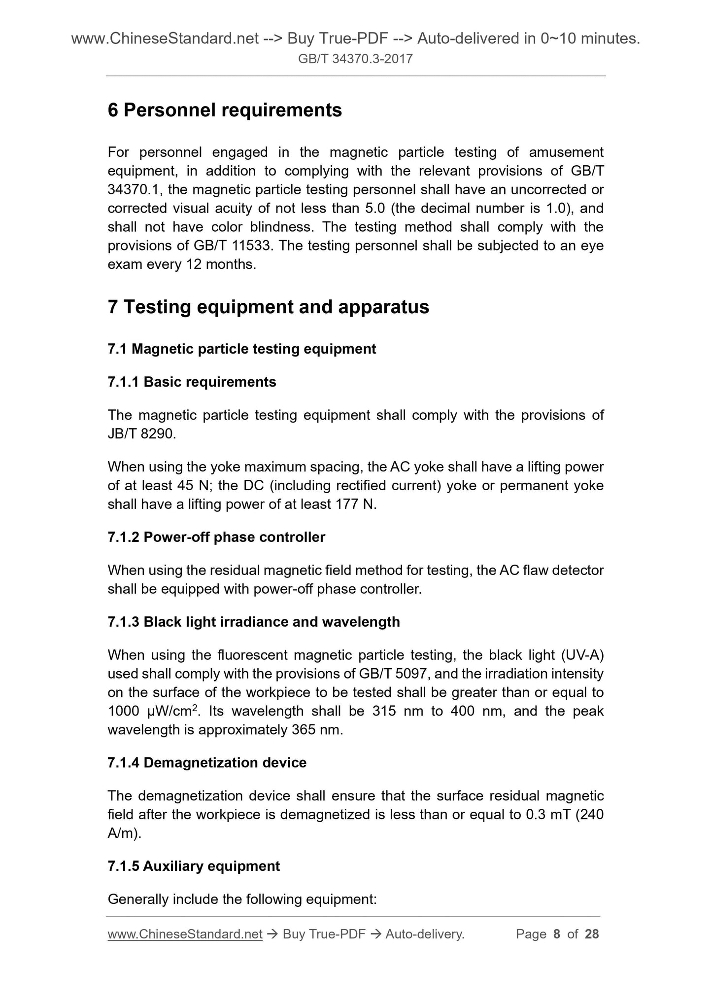
6 personnel requirements
Personnel engaged in the magnetic particle testing of amusement facilities shall not comply with the relevant provisions of GB/T 34370.1.
The corrected or corrected visual acuity should be no less than 5.0 (the decimal number is 1.0), and there should be no color blindness. The test method should meet the requirements of GB/T 11533.
The examiner should perform an eye exam every 12 months.
7 Testing equipment and equipment
7.1 Magnetic particle testing equipment
7.1.1 Basic requirements
The magnetic particle testing equipment shall comply with the provisions of JB/T 8290.
When using the maximum yoke spacing, the AC yoke should have at least 45N lifting force; DC (including rectifying) yoke or permanent
The yoke should have a lifting force of at least 177N.
7.1.2 Power-off phase controller
When using the residual magnetic method to detect, the AC flaw detector should be equipped with a power-off phase controller.
7.1.3 Black light irradiance and wavelength
When using fluorescent magnetic particle detection, the black light (UV-A) used shall comply with the provisions of GB/T 5097 and the surface of the workpiece to be inspected.
The illumination intensity should be greater than or equal to 1000 μW/cm 2 , the wavelength should be 315 nm to 400 nm, and the peak wavelength should be approximately 365 nm.
7.1.4 Demagnetization device
The demagnetization device shall ensure that the surface remanence after the workpiece is demagnetized is less than or equal to 0.3 mT (240 A/m).
7.1.5 Auxiliary equipment
Generally include the following equipment.
a) magnetic field strength meter;
b) A1, C, D and M1 test strips;
c) a magnetic suspension concentration sedimentation tube;
d) 2 times to 10 times magnifying glass;
e) white light meter;
f) black light;
g) black light irradiation meter;
h) millitesla;
i) Gauss meter;
j) Contrast enhancer.
7.2 Magnetic powder, carrier liquid and magnetic suspension
7.2.1 Magnetic powder
The magnetic powder should have high magnetic permeability, low coercivity and low remanence, and should have a high contrast with the surface color of the workpiece to be inspected. Magnetic powder
Other requirements for particle size and performance shall be in accordance with JB/T 6063.
7.2.2 Carrier liquid
The wet method should use water or a low viscosity oil-based carrier liquid as the dispersion medium. If water is used as the carrier liquid, appropriate rust inhibitors and surface activities should be added.
Sex agent, add defoamer if necessary. The viscosity of the oil-based carrier liquid should be no more than 3.0mm2/s at 38 °C, and should not be greater than the minimum use temperature.
5.0mm2/s, flash point not lower than 94 ° C, and no fluorescence and no odor.
7.2.3 Magnetic suspension
The concentration of the magnetic suspension should be determined according to factors such as the type of magnetic powder, the particle size, the application method, and the surface state of the workpiece to be inspected. In general, magnetic
The concentration range of the suspension should meet the requirements of Table 1. The magnetic suspension should be thoroughly stirred before the measurement.
Table 1 Magnetic suspension concentration
Magnetic powder type preparation concentration/(g/L) Precipitation concentration (solid content)/(mL/100mL)
Non-fluorescent magnetic powder 10.0~25.0 1.2~2.4
Fluorescent magnetic powder 0.5~3.0 0.1~0.4
7.3 Test piece
7.3.1 Standard test strips
7.3.1.1 Standard test strips are mainly used to verify the comprehensive performance of magnetic particle testing equipment, magnetic powder and magnetic suspension, and the effective magnetic field strength of the surface of the workpiece to be inspected.
And direction, effective detection area and magnetization method are correct; standard test strips are A1, C, D and M1. Specifications, dimensions and figures
See Table 2. Standard test pieces of type A1, C and D shall comply with the provisions of GB/T 23907.
7.3.1.2 Generally, the A1-30/100 standard test piece should be used for magnetic particle testing. When detecting narrow parts such as weld bevels, due to dimensional relationship,
When the A1 type standard test piece is inconvenient to use, the C-15/50 type standard test piece is generally available. Type D standard test strips are available when required by the user. To be more
Accurately infer the magnetization state of the surface of the workpiece to be inspected. When the user needs or the technical documents specify, the M1 standard test piece can be selected.
Table 2 Types, specifications and graphics of standard test strips
Type specification. defect groove depth/test piece thickness/μm pattern and size/mm
A1
A1-7/50
A1-15/50
A1-30/50
A1-15/100
A1-30/100
A1-60/100
C-8/50
C-15/50
D-7/50
D-15/50
M1
Φ12mm 7/50
Φ9mm 15/50
Φ6mm 30/50
Note. Type C standard test strips can be cut into 5 small test strips for use.
7.3.1.3 Standard test strip usage.
a) The standard test piece is suitable for the continuous magnetization method. When using it, the test piece should have no artificial defects facing outward. In order to make the test piece in contact with the surface to be inspected
Good, use a transparent tape to flatten it on the surface to be inspected, and note that the tape does not cover the artificial defects on the test piece.
b) The standard test piece shall not be used continuously if it has rust, pleats or changes in magnetic properties.
7.3.2 Magnetic field indicator
The magnetic field indicator is a kind of coarseness indicating the direction of the magnetic field on the surface of the workpiece to be inspected, the effective detection area, and the correct magnetization method.
A slight verification tool, but not as a quantitative indication of the strength of the magnetic field and its distribution. Its geometric dimensions are shown in Figure 4.
The unit is mm
Figure 4 Magnetic field indicator
7.4 Magnetic suspension performance test
7.4.1 Comprehensive performance test
Before the start of the daily inspection work, the standard test piece is used to check the comprehensive performance (system sensitivity) of the magnetic particle testing equipment and the magnetic powder and magnetic suspension.
7.4.2 Magnetic suspension wetting performance test
The magnetic suspension wetting performance test shall be carried out before each test. Applying a magnetic suspension to the surface of the workpiece to be inspected, if the liquid film of the magnetic suspension is
Evenly continuous, the wettability of the magnetic suspension is acceptable; if the liquid film is broken, the wettability of the magnetic suspension is unacceptable.
7.5 yoke lifting force check
The lifting force of the yoke should be checked at least once every six months. It should be re-calibrated after the yoke damage is repaired.
7.6 Auxiliary instrument calibration
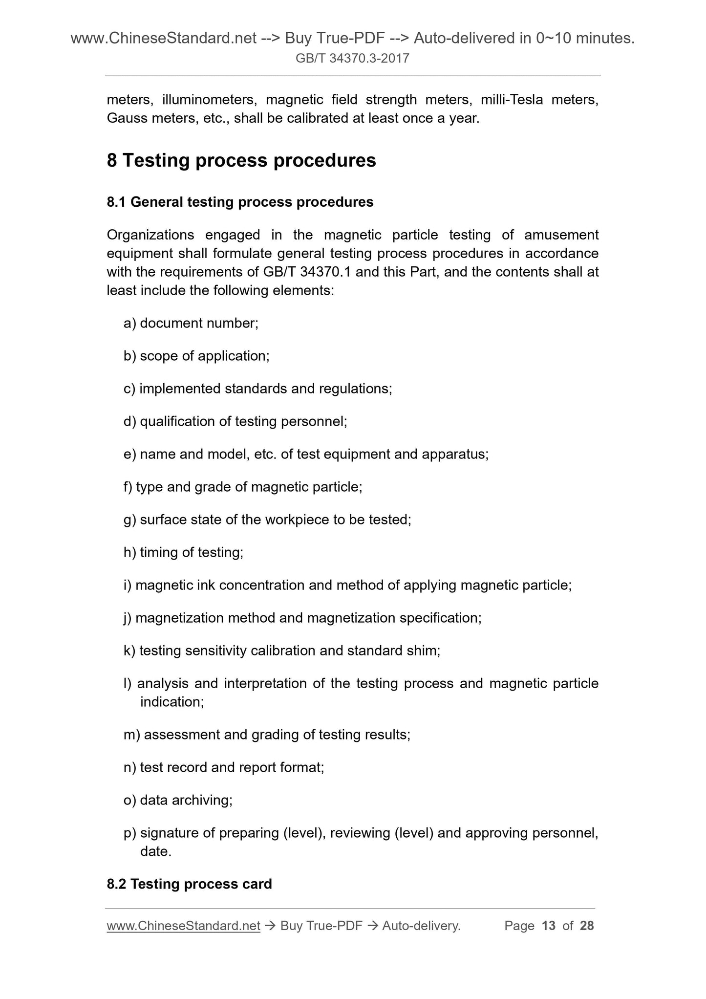
Auxiliary instruments for magnetic particle testing, such as black light irradiators, illuminometers, magnetic field strength meters, millitesla meters, Gauss meters, etc., should be at least annually
Check it once.
8 Test procedure
8.1 General Inspection Process Procedures
Units engaged in magnetic particle testing of amusement facilities shall formulate general testing procedures in accordance with GB/T 34370.1 and the requirements of this part.
The content should at least include the following elements.
a) the file number;
b) scope of application;
c) implementation of standards and regulations;
d) the qualification of the test personnel;
e) test equipment name and model, etc.;
f) type and grade of magnetic powder;
g) the surface state of the workpiece being inspected;
h) timing of detection;
i) magnetic suspension concentration and method...
Get Quotation: Click GB/T 34370.3-2017 (Self-service in 1-minute)
Historical versions (Master-website): GB/T 34370.3-2017
Preview True-PDF (Reload/Scroll-down if blank)
GB/T 34370.3-2017: Nondestructive testing of amusement equipment - Part 3: Magnetic particle testing
GB/T 34370.3-2017
Nondestructive testing of amusement equipments--Part 3. Magnetic particle testing
ICS 97.200.40
Y57
National Standards of People's Republic of China
Non-destructive testing of rides
Part 3. Magnetic particle testing
Part 3.Magneticparticletesting
Released on.2017-09-29
2018-04-01 implementation
General Administration of Quality Supervision, Inspection and Quarantine of the People's Republic of China
China National Standardization Administration issued
Foreword
GB/T 34370 "Non-destructive testing of amusement facilities" is divided into the following six parts.
--- Part 1. General;
--- Part 2. Visual inspection;
--- Part 3. Magnetic particle testing;
--- Part 4. Penetration testing;
---Part 5. Ultrasonic testing;
--- Part 6. Radiation detection.
This part is the third part of GB/T 34370.
This part is drafted in accordance with the rules given in GB/T 1.1-2009.
This part is proposed and managed by the National Technical Committee for Cableway and Amusement Facilities Standardization (SAC/TC250).
This section drafted by. China Special Equipment Inspection and Research Institute, Hebei Province Special Equipment Supervision and Inspection Institute, Jining Luke Testing Equipment Limited
Company, Shandong Kejie Engineering Testing Co., Ltd., Hebei University, Beijing Shibaolai Amusement Equipment Co., Ltd.
The main drafters of this section. Shen Gongtian, Wu Zhanwen, Guo Ningchao, Hu Bin, Zhang Junjiao, Wei Weijin, Dou Quan, Zhang Jinsong, Ye Chao, Wan Qiang,
Liang Yumei, Wang Fang, Sun Jianxi.
Non-destructive testing of rides
Part 3. Magnetic particle testing
1 Scope
This part of GB/T 34370 specifies the yoke method, the coil method and the magnetic powder detection method and quality classification requirements of the ride.
This section applies to the detection of ferromagnetic raw materials, parts and welded joint surfaces and near surface defects of amusement facilities.
This section does not apply to the detection of austenitic stainless steel and other non-ferromagnetic materials.
2 Normative references
The following documents are indispensable for the application of this document. For dated references, only dated versions apply to this article.
Pieces. For undated references, the latest edition (including all amendments) applies to this document.
GB/T 5097 Non-destructive testing for penetration testing and magnetic particle testing conditions
GB/T 11533 standard logarithmic visual acuity chart
GB/T 12604.5 Non-destructive testing terminology magnetic particle testing
GB/T 20306 rides terminology
GB/T 20737 General Terms and Definitions for Nondestructive Testing
GB/T 23907 Non-destructive testing magnetic particle testing test piece
GB/T 34370.1 Non-destructive testing of rides - Part 1. General
JB/T 6063 Non-destructive testing materials for magnetic particle testing
JB/T 8290 non-destructive testing instrument magnetic particle flaw detector
3 Terms and definitions
The following terms and definitions as defined in GB/T 12604.5, GB/T 20306 and GB/T 20737 apply to this document.
3.1
Excessive background excessivebackground
Due to the magnetic field strength and the concentration of the magnetic suspension being too large, the surface of the workpiece is rough or contaminated to produce a background of the magnetic trace that hinders the evaluation of the magnetic trace analysis.
3.2
Related display relevantindication
The magnetic trace formed by the magnetic field caused by the leakage magnetic field generated by the defect (crack, unfused, stomata, slag, etc.) during magnetic particle detection is called phase
Off display. Also known as the defect display.
3.3
Non-relevant indication
The magnetic trace formed by the magnetic field of the magnetic field caused by the magnetic field cross section mutation and the difference in magnetic permeability of the material is called non-correlation.
display.
3.4
False display falseindication
False display
The magnetic trace formed by the magnetic powder adsorbed by the leakage magnetic field is not displayed.
3.5
Tangential magnetic field strength tangentmagneticfieldstrength
A component of the magnetic field strength parallel to the surface of the workpiece being inspected.
3.6
Ambient visible ambientvisiblelight
In the dark area, the visible light measured from the surface of the workpiece under black light.
4 Method summary
After the ferromagnetic material workpiece is magnetized, due to the discontinuity, the magnetic field lines on the surface of the workpiece and the near surface are locally distorted.
Leaking magnetic field, adsorbing magnetic powder applied on the surface of the workpiece, forming visually visible magnetic marks under suitable illumination, thereby showing discontinuous positions,
Size and shape. Fig. 1 to Fig. 3 are schematic diagrams of the yoke method, the coil method and the axial energization method, respectively.
Description.
1---current;
2---iron core;
3---Defects.
Figure 1 yoke method (magnetic trace display)
Description.
1---current;
2---workpiece;
3---defects;
4---coil.
Figure 2 Coil method
Description.
1---current;
2---defects;
3---workpiece;
4---electrode.
Figure 3 axial conduction method
5 Safety requirements
The safety requirements during the inspection process include at least.
a) The inspection personnel shall comply with the safety requirements of the site to be inspected, wear protective overalls and wear relevant defense according to the requirements of the inspection site.
Protective equipment;
b) Care should be taken to avoid various safety hazards such as bumps, electric shock, falling, squeezing, shearing, entanglement, slipping, drowning, burns, etc.
c) When using a hydromagnetic suspension to detect amusement facilities, prevent insulation failure or electrical short circuit;
d) When using fluorescent magnetic powder detection, the filter of the black light shall not have cracks, and the black light shall be prevented from directly illuminating the human eye;
e) The axial energization method should not be used in flammable and explosive places, and it should be prevented from burning in other places.
This chapter does not list all the safety requirements for testing. Users using this section should establish safety guidelines prior to testing.
6 personnel requirements
Personnel engaged in the magnetic particle testing of amusement facilities shall not comply with the relevant provisions of GB/T 34370.1.
The corrected or corrected visual acuity should be no less than 5.0 (the decimal number is 1.0), and there should be no color blindness. The test method should meet the requirements of GB/T 11533.
The examiner should perform an eye exam every 12 months.
7 Testing equipment and equipment
7.1 Magnetic particle testing equipment
7.1.1 Basic requirements
The magnetic particle testing equipment shall comply with the provisions of JB/T 8290.
When using the maximum yoke spacing, the AC yoke should have at least 45N lifting force; DC (including rectifying) yoke or permanent
The yoke should have a lifting force of at least 177N.
7.1.2 Power-off phase controller
When using the residual magnetic method to detect, the AC flaw detector should be equipped with a power-off phase controller.
7.1.3 Black light irradiance and wavelength
When using fluorescent magnetic particle detection, the black light (UV-A) used shall comply with the provisions of GB/T 5097 and the surface of the workpiece to be inspected.
The illumination intensity should be greater than or equal to 1000 μW/cm 2 , the wavelength should be 315 nm to 400 nm, and the peak wavelength should be approximately 365 nm.
7.1.4 Demagnetization device
The demagnetization device shall ensure that the surface remanence after the workpiece is demagnetized is less than or equal to 0.3 mT (240 A/m).
7.1.5 Auxiliary equipment
Generally include the following equipment.
a) magnetic field strength meter;
b) A1, C, D and M1 test strips;
c) a magnetic suspension concentration sedimentation tube;
d) 2 times to 10 times magnifying glass;
e) white light meter;
f) black light;
g) black light irradiation meter;
h) millitesla;
i) Gauss meter;
j) Contrast enhancer.
7.2 Magnetic powder, carrier liquid and magnetic suspension
7.2.1 Magnetic powder
The magnetic powder should have high magnetic permeability, low coercivity and low remanence, and should have a high contrast with the surface color of the workpiece to be inspected. Magnetic powder
Other requirements for particle size and performance shall be in accordance with JB/T 6063.
7.2.2 Carrier liquid
The wet method should use water or a low viscosity oil-based carrier liquid as the dispersion medium. If water is used as the carrier liquid, appropriate rust inhibitors and surface activities should be added.
Sex agent, add defoamer if necessary. The viscosity of the oil-based carrier liquid should be no more than 3.0mm2/s at 38 °C, and should not be greater than the minimum use temperature.
5.0mm2/s, flash point not lower than 94 ° C, and no fluorescence and no odor.
7.2.3 Magnetic suspension
The concentration of the magnetic suspension should be determined according to factors such as the type of magnetic powder, the particle size, the application method, and the surface state of the workpiece to be inspected. In general, magnetic
The concentration range of the suspension should meet the requirements of Table 1. The magnetic suspension should be thoroughly stirred before the measurement.
Table 1 Magnetic suspension concentration
Magnetic powder type preparation concentration/(g/L) Precipitation concentration (solid content)/(mL/100mL)
Non-fluorescent magnetic powder 10.0~25.0 1.2~2.4
Fluorescent magnetic powder 0.5~3.0 0.1~0.4
7.3 Test piece
7.3.1 Standard test strips
7.3.1.1 Standard test strips are mainly used to verify the comprehensive performance of magnetic particle testing equipment, magnetic powder and magnetic suspension, and the effective magnetic field strength of the surface of the workpiece to be inspected.
And direction, effective detection area and magnetization method are correct; standard test strips are A1, C, D and M1. Specifications, dimensions and figures
See Table 2. Standard test pieces of type A1, C and D shall comply with the provisions of GB/T 23907.
7.3.1.2 Generally, the A1-30/100 standard test piece should be used for magnetic particle testing. When detecting narrow parts such as weld bevels, due to dimensional relationship,
When the A1 type standard test piece is inconvenient to use, the C-15/50 type standard test piece is generally available. Type D standard test strips are available when required by the user. To be more
Accurately infer the magnetization state of the surface of the workpiece to be inspected. When the user needs or the technical documents specify, the M1 standard test piece can be selected.
Table 2 Types, specifications and graphics of standard test strips
Type specification. defect groove depth/test piece thickness/μm pattern and size/mm
A1
A1-7/50
A1-15/50
A1-30/50
A1-15/100
A1-30/100
A1-60/100
C-8/50
C-15/50
D-7/50
D-15/50
M1
Φ12mm 7/50
Φ9mm 15/50
Φ6mm 30/50
Note. Type C standard test strips can be cut into 5 small test strips for use.
7.3.1.3 Standard test strip usage.
a) The standard test piece is suitable for the continuous magnetization method. When using it, the test piece should have no artificial defects facing outward. In order to make the test piece in contact with the surface to be inspected
Good, use a transparent tape to flatten it on the surface to be inspected, and note that the tape does not cover the artificial defects on the test piece.
b) The standard test piece shall not be used continuously if it has rust, pleats or changes in magnetic properties.
7.3.2 Magnetic field indicator
The magnetic field indicator is a kind of coarseness indicating the direction of the magnetic field on the surface of the workpiece to be inspected, the effective detection area, and the correct magnetization method.
A slight verification tool, but not as a quantitative indication of the strength of the magnetic field and its distribution. Its geometric dimensions are shown in Figure 4.
The unit is mm
Figure 4 Magnetic field indicator
7.4 Magnetic suspension performance test
7.4.1 Comprehensive performance test
Before the start of the daily inspection work, the standard test piece is used to check the comprehensive performance (system sensitivity) of the magnetic particle testing equipment and the magnetic powder and magnetic suspension.
7.4.2 Magnetic suspension wetting performance test
The magnetic suspension wetting performance test shall be carried out before each test. Applying a magnetic suspension to the surface of the workpiece to be inspected, if the liquid film of the magnetic suspension is
Evenly continuous, the wettability of the magnetic suspension is acceptable; if the liquid film is broken, the wettability of the magnetic suspension is unacceptable.
7.5 yoke lifting force check
The lifting force of the yoke should be checked at least once every six months. It should be re-calibrated after the yoke damage is repaired.
7.6 Auxiliary instrument calibration
Auxiliary instruments for magnetic particle testing, such as black light irradiators, illuminometers, magnetic field strength meters, millitesla meters, Gauss meters, etc., should be at least annually
Check it once.
8 Test procedure
8.1 General Inspection Process Procedures
Units engaged in magnetic particle testing of amusement facilities shall formulate general testing procedures in accordance with GB/T 34370.1 and the requirements of this part.
The content should at least include the following elements.
a) the file number;
b) scope of application;
c) implementation of standards and regulations;
d) the qualification of the test personnel;
e) test equipment name and model, etc.;
f) type and grade of magnetic powder;
g) the surface state of the workpiece being inspected;
h) timing of detection;
i) magnetic suspension concentration and method...
Share