1
/
of
12
www.ChineseStandard.us -- Field Test Asia Pte. Ltd.
GB/T 34370.5-2017 English PDF (GB/T34370.5-2017)
GB/T 34370.5-2017 English PDF (GB/T34370.5-2017)
Regular price
$495.00
Regular price
Sale price
$495.00
Unit price
/
per
Shipping calculated at checkout.
Couldn't load pickup availability
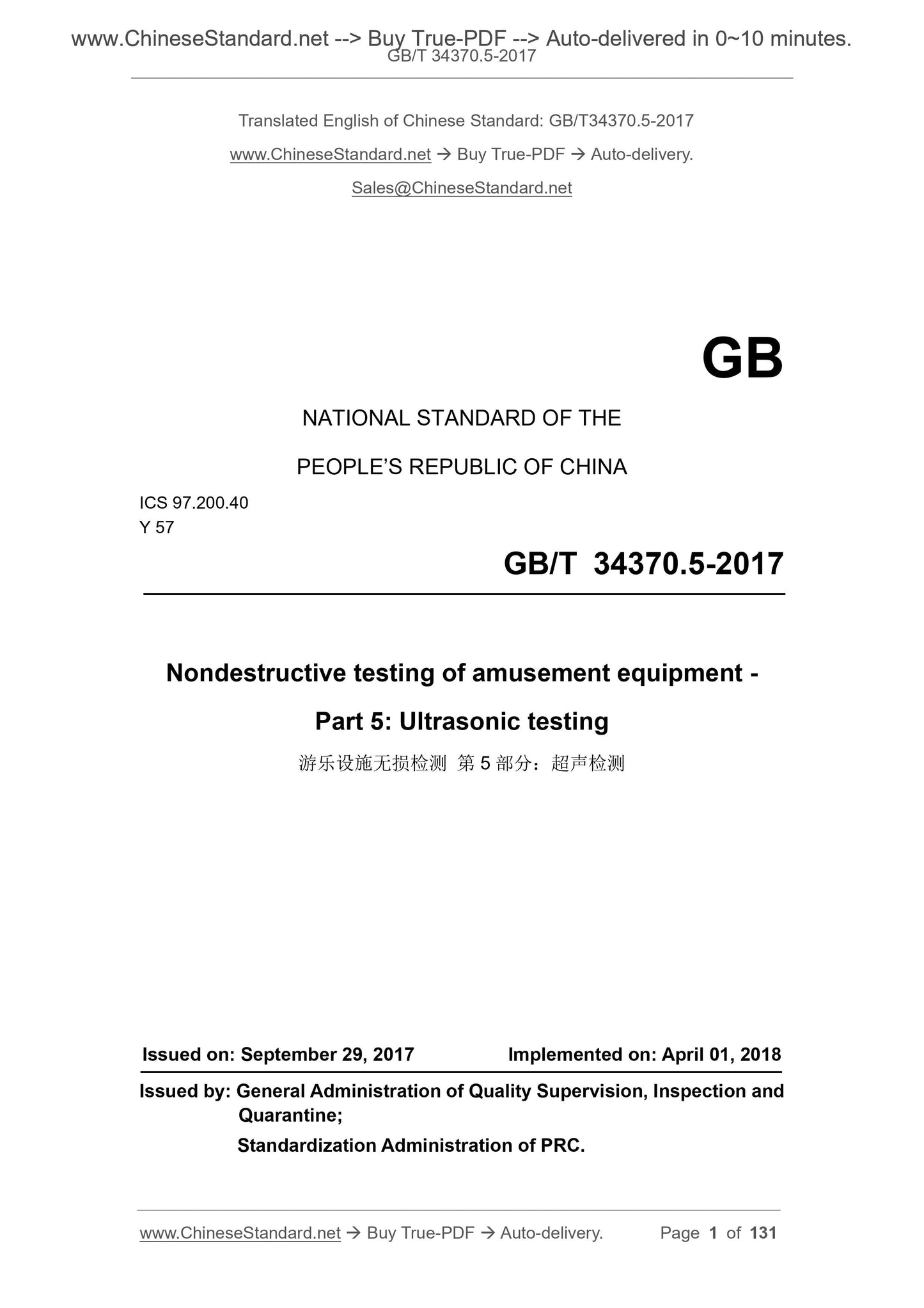
GB/T 34370.5-2017: Nondestructive testing of amusement equipment - Part 5: Ultrasonic testing
Delivery: 9 seconds. Download (& Email) true-PDF + Invoice.
Get Quotation: Click GB/T 34370.5-2017 (Self-service in 1-minute)
Historical versions (Master-website): GB/T 34370.5-2017
Preview True-PDF (Reload/Scroll-down if blank)
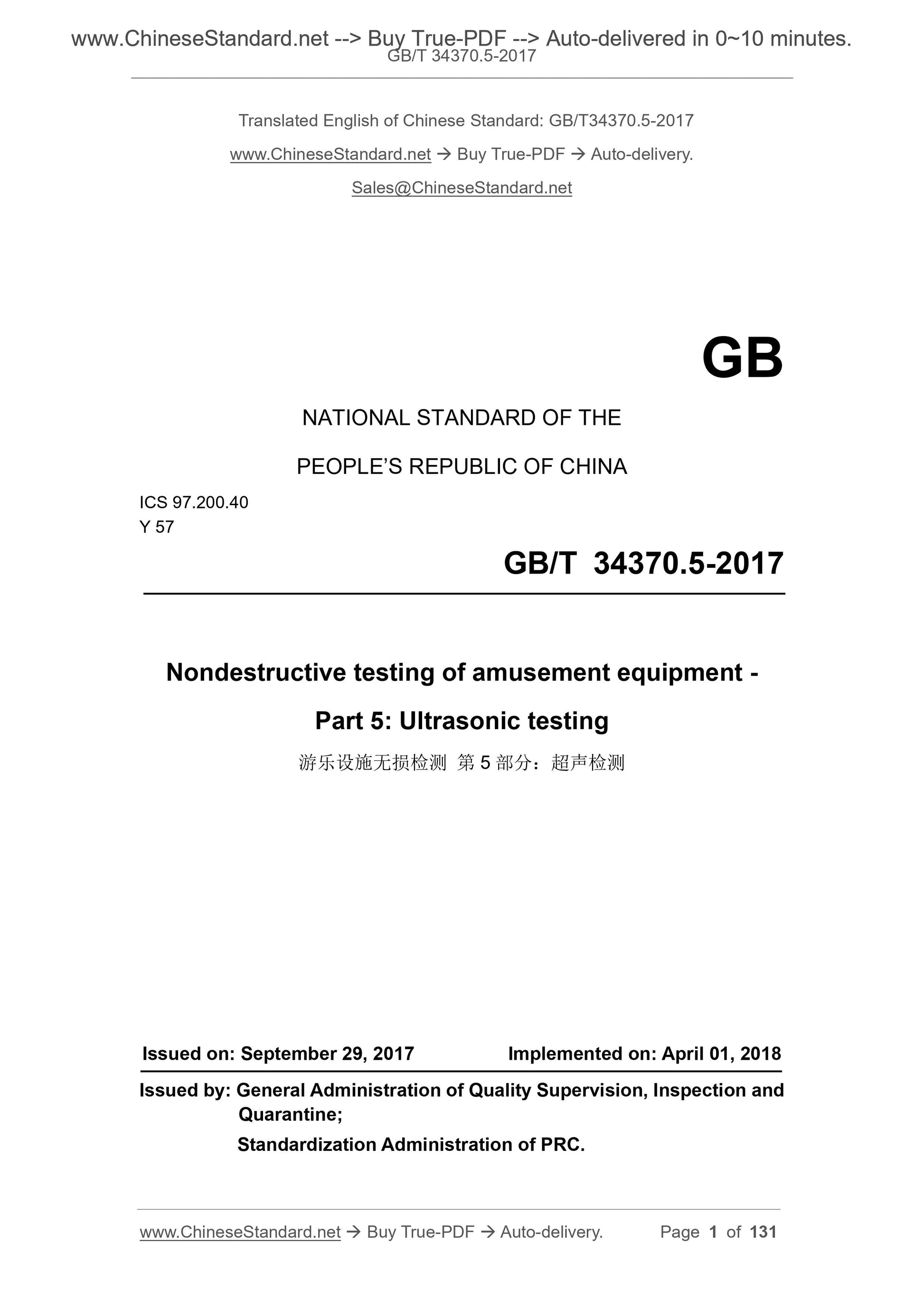
GB/T 34370.5-2017
GB
NATIONAL STANDARD OF THE
PEOPLE’S REPUBLIC OF CHINA
ICS 97.200.40
Y 57
Nondestructive testing of amusement equipment -
Part 5. Ultrasonic testing
ISSUED ON. SEPTEMBER 29, 2017
IMPLEMENTED ON. APRIL 01, 2018
Issued by. General Administration of Quality Supervision, Inspection and
Quarantine;
Standardization Administration of PRC.
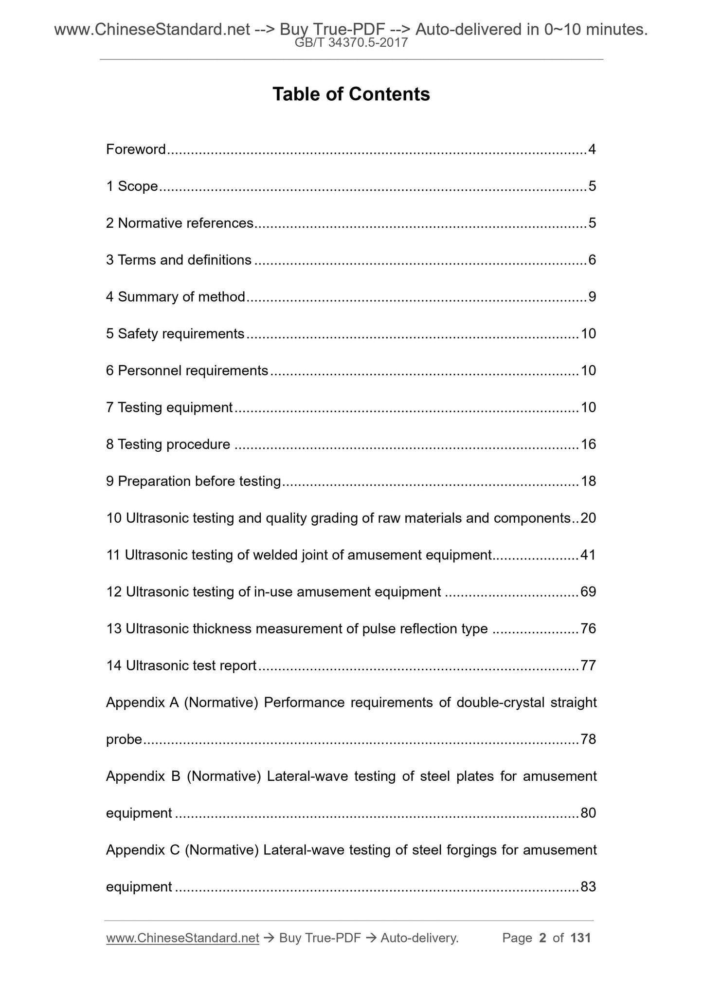
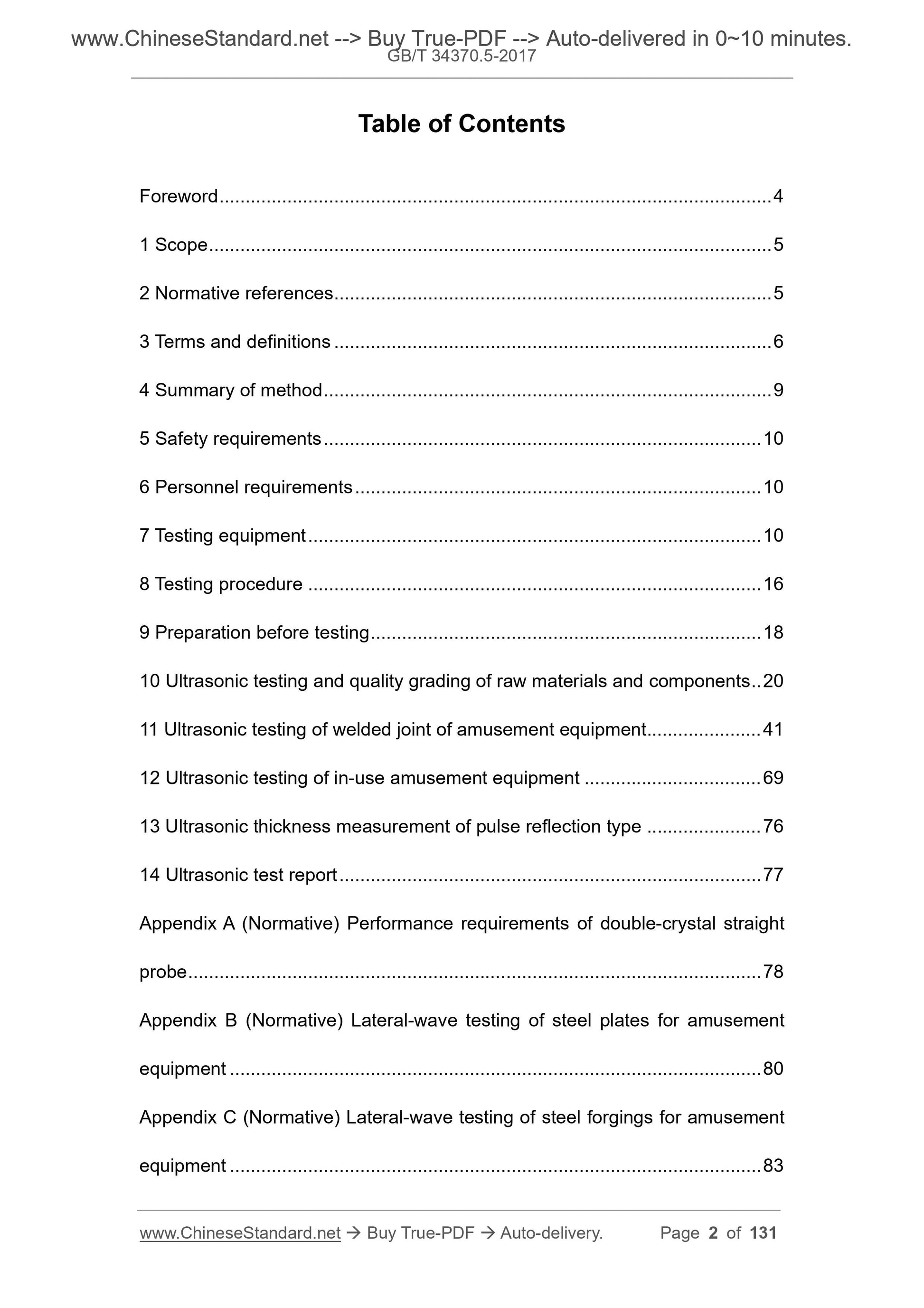
Table of Contents
Foreword ... 4
1 Scope ... 5
2 Normative references ... 5
3 Terms and definitions ... 6
4 Summary of method ... 9
5 Safety requirements ... 10
6 Personnel requirements ... 10
7 Testing equipment ... 10
8 Testing procedure ... 16
9 Preparation before testing ... 18
10 Ultrasonic testing and quality grading of raw materials and components .. 20
11 Ultrasonic testing of welded joint of amusement equipment ... 41
12 Ultrasonic testing of in-use amusement equipment ... 69
13 Ultrasonic thickness measurement of pulse reflection type ... 76
14 Ultrasonic test report ... 77
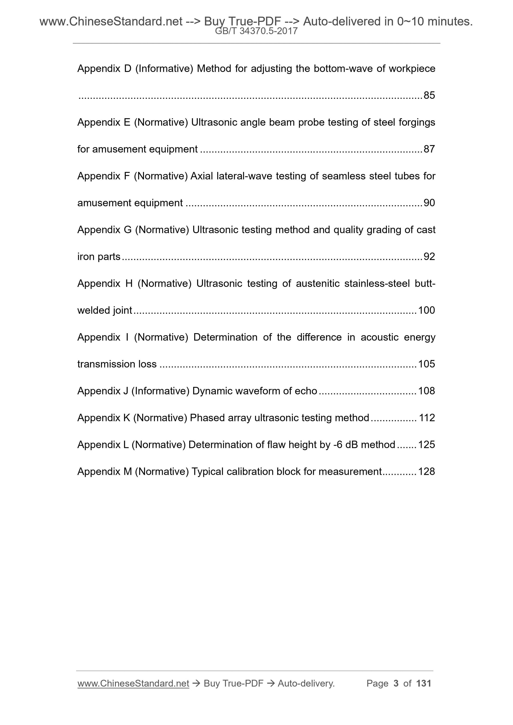
Appendix A (Normative) Performance requirements of double-crystal straight
probe ... 78
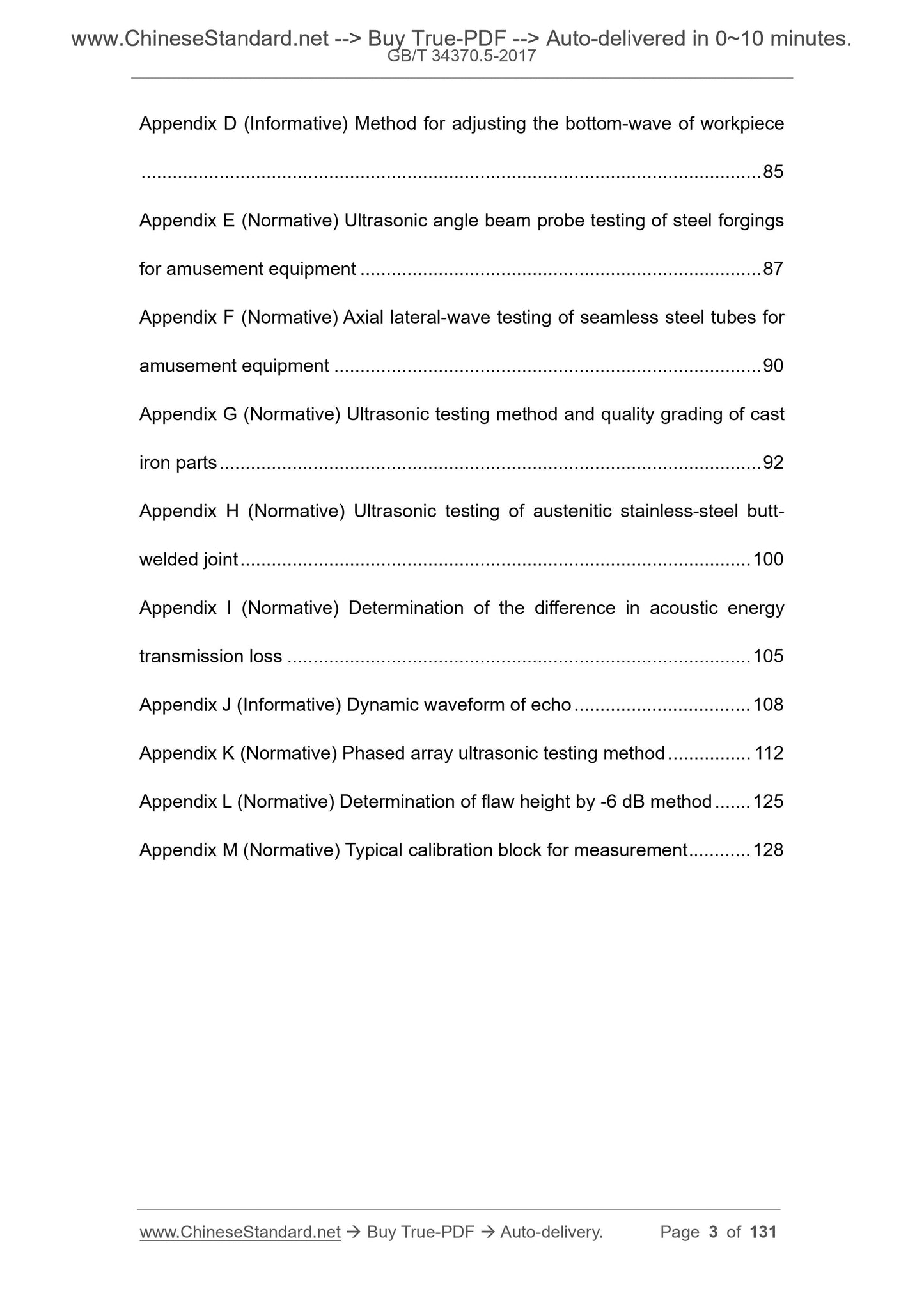
Appendix B (Normative) Lateral-wave testing of steel plates for amusement
equipment ... 80
Appendix C (Normative) Lateral-wave testing of steel forgings for amusement
equipment ... 83
Appendix D (Informative) Method for adjusting the bottom-wave of workpiece
... 85
Appendix E (Normative) Ultrasonic angle beam probe testing of steel forgings
for amusement equipment ... 87
Appendix F (Normative) Axial lateral-wave testing of seamless steel tubes for
amusement equipment ... 90
Appendix G (Normative) Ultrasonic testing method and quality grading of cast
iron parts ... 92
Appendix H (Normative) Ultrasonic testing of austenitic stainless-steel butt-
welded joint ... 100
Appendix I (Normative) Determination of the difference in acoustic energy
transmission loss ... 105
Appendix J (Informative) Dynamic waveform of echo ... 108
Appendix K (Normative) Phased array ultrasonic testing method ... 112
Appendix L (Normative) Determination of flaw height by -6 dB method ... 125
Appendix M (Normative) Typical calibration block for measurement ... 128
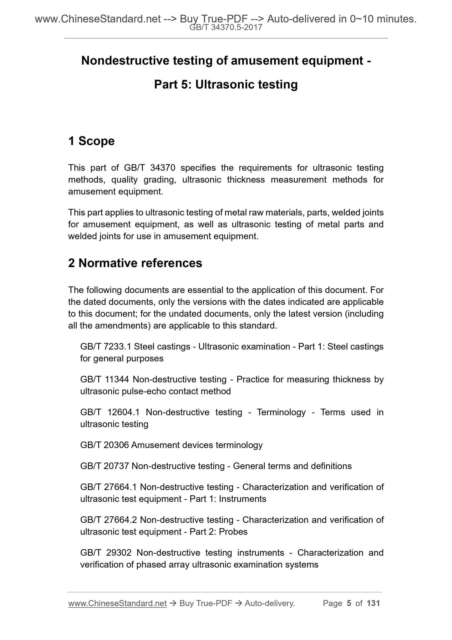
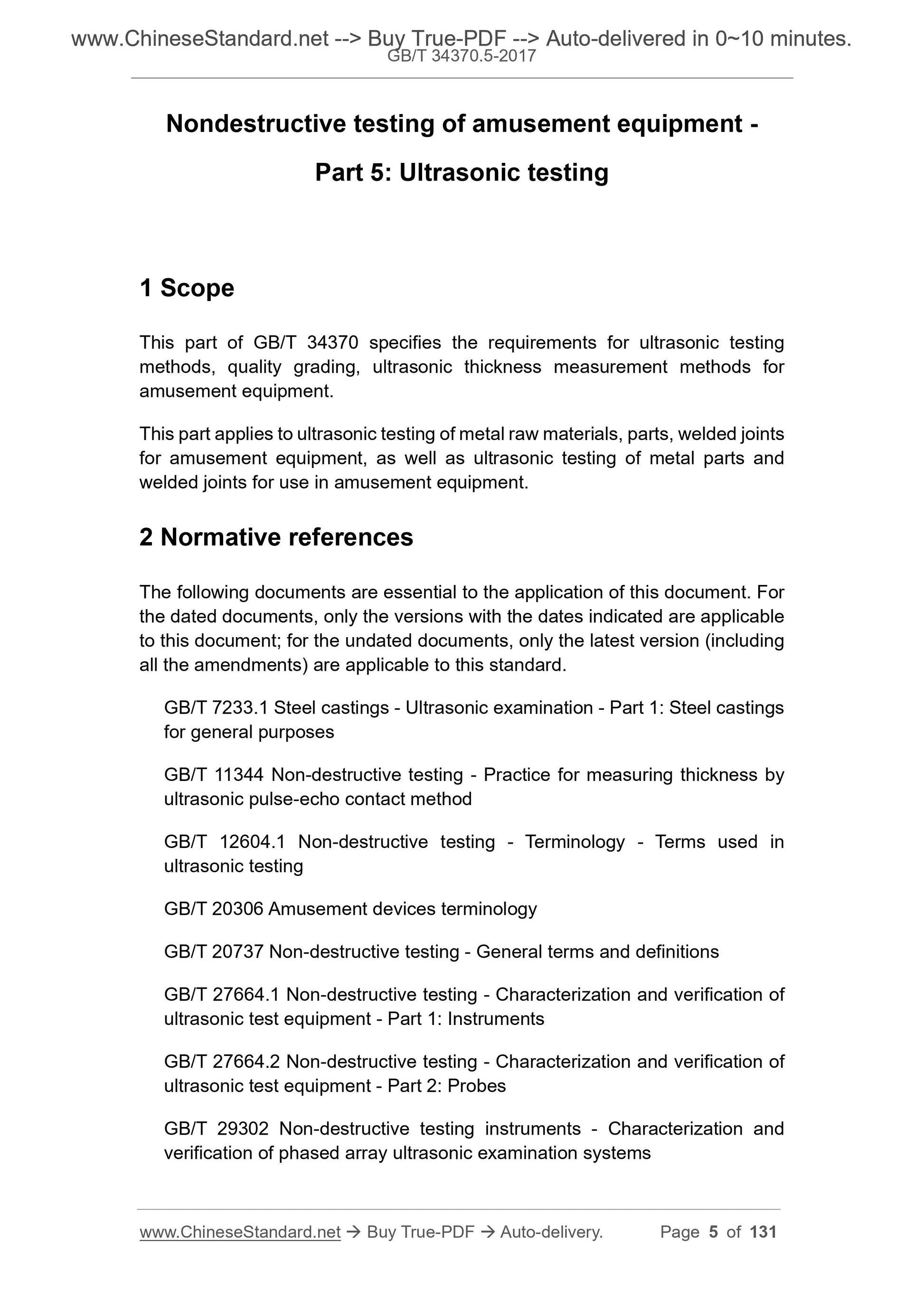
Nondestructive testing of amusement equipment -
Part 5. Ultrasonic testing
1 Scope
This part of GB/T 34370 specifies the requirements for ultrasonic testing
methods, quality grading, ultrasonic thickness measurement methods for
amusement equipment.
This part applies to ultrasonic testing of metal raw materials, parts, welded joints
for amusement equipment, as well as ultrasonic testing of metal parts and
welded joints for use in amusement equipment.
2 Normative references
The following documents are essential to the application of this document. For
the dated documents, only the versions with the dates indicated are applicable
to this document; for the undated documents, only the latest version (including
all the amendments) are applicable to this standard.
GB/T 7233.1 Steel castings - Ultrasonic examination - Part 1. Steel castings
for general purposes
GB/T 11344 Non-destructive testing - Practice for measuring thickness by
ultrasonic pulse-echo contact method
GB/T 12604.1 Non-destructive testing - Terminology - Terms used in
ultrasonic testing
GB/T 20306 Amusement devices terminology
GB/T 20737 Non-destructive testing - General terms and definitions
GB/T 27664.1 Non-destructive testing - Characterization and verification of
ultrasonic test equipment - Part 1. Instruments
GB/T 27664.2 Non-destructive testing - Characterization and verification of
ultrasonic test equipment - Part 2. Probes
GB/T 29302 Non-destructive testing instruments - Characterization and
verification of phased array ultrasonic examination systems
GB/T 34370.1 Nondestructive testing of amusement equipment - Part 1.
General requirement
JB/T 8428 Non-destructive testing - General specification for ultrasonic
blocks
JB/T 9214 Non-destructive testing - Test methods for evaluating
performance characteristics of A-scan pulse-echo ultrasonic testing systems
JB/T 10062 Testing methods for performance of probes used in ultrasonic
flaw testing
JB/T 11604 Non-destructive testing instruments - Ultrasonic thickness gauge
JB/T 11731 Non-destructive testing - General specification for ultrasonic
phased array probe
JB/T 11779 Non-destructive testing instrument - Specifications for phased
array ultrasonic detectors
3 Terms and definitions
The terms and definitions as defined in GB/T 12604.1, GB/T 20306, GB/T
20737, GB/T 34370.1 as well as the following terms and definitions apply to this
document.
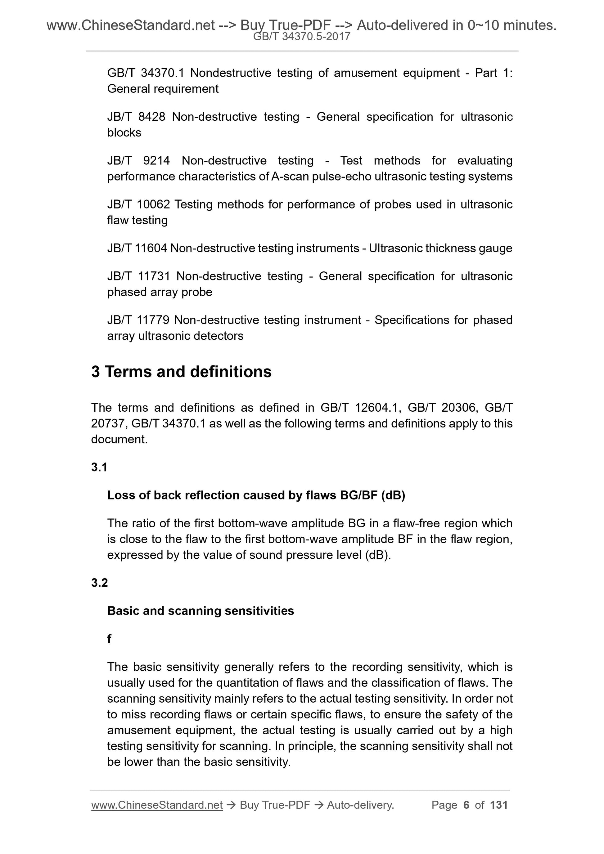
3.1
Loss of back reflection caused by flaws BG/BF (dB)
The ratio of the first bottom-wave amplitude BG in a flaw-free region which
is close to the flaw to the first bottom-wave amplitude BF in the flaw region,
expressed by the value of sound pressure level (dB).
3.2
Basic and scanning sensitivities
The basic sensitivity generally refers to the recording sensitivity, which is
usually used for the quantitation of flaws and the classification of flaws. The
scanning sensitivity mainly refers to the actual testing sensitivity. In order not
to miss recording flaws or certain specific flaws, to ensure the safety of the
amusement equipment, the actual testing is usually carried out by a high
testing sensitivity for scanning. In principle, the scanning sensitivity shall not
be lower than the basic sensitivity.
probes.
7.1.2 Ultrasonic testing equipment shall have a certificate of product quality or
a certificate of conformity.
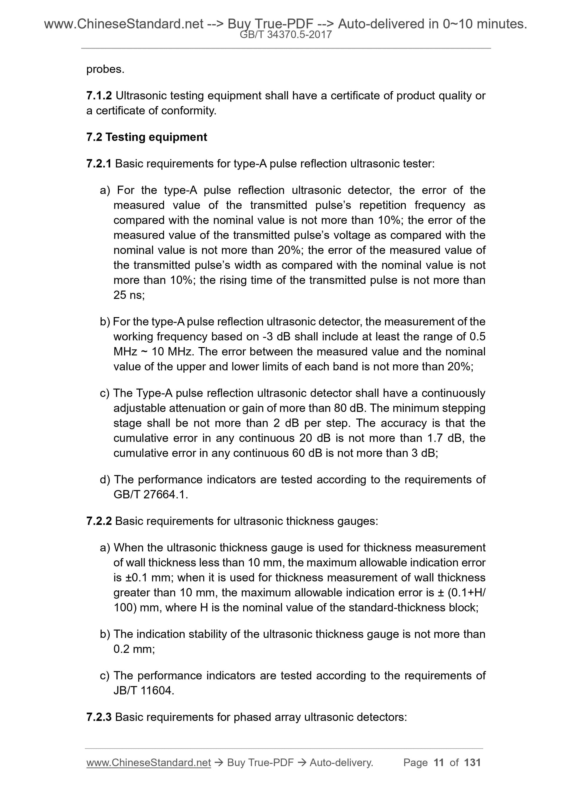
7.2 Testing equipment
7.2.1 Basic requirements for type-A pulse reflection ultrasonic tester.
a) For the type-A pulse reflection ultrasonic detector, the error of the
measured value of the transmitted pulse’s repetition frequency as
compared with the nominal value is not more than 10%; the error of the
measured value of the transmitted pulse’s voltage as compared with the
nominal value is not more than 20%; the error of the measured value of
the transmitted pulse’s width as compared with the nominal value is not
more than 10%; the rising time of the transmitted pulse is not more than
25 ns;
b) For the type-A pulse reflection ultrasonic detector, the measurement of the
working frequency based on -3 dB shall include at least the range of 0.5
MHz ~ 10 MHz. The error between the measured value and the nominal
value of the upper and lower limits of each band is not more than 20%;
c) The Type-A pulse reflection ultrasonic detector shall have a continuously
adjustable attenuation or gain of more than 80 dB. The minimum stepping
stage shall be not more than 2 dB per step. The accuracy is that the
cumulative error in any continuous 20 dB is not more than 1.7 dB, the
cumulative error in any continuous 60 dB is not more than 3 dB;
d) The performance indicators are tested according to the requirements of
GB/T 27664.1.
7.2.2 Basic requirements for ultrasonic thickness gauges.
a) When the ultrasonic thickness gauge is used for thickness measurement
of wall thickness less than 10 mm, the maximum allowable indication error
is ±0.1 mm; when it is used for thickness measurement of wall thickness
greater than 10 mm, the maximum allowable indication error is ± (0.1+H/
100) mm, where H is the nominal value of the standard-thickness block;
b) The indication stability of the ultrasonic thickness gauge is not more than
0.2 mm;
c) The performance indicators are tested according to the requirements of
JB/T 11604.
7.2.3 Basic requirements for phased array ultrasonic detectors.
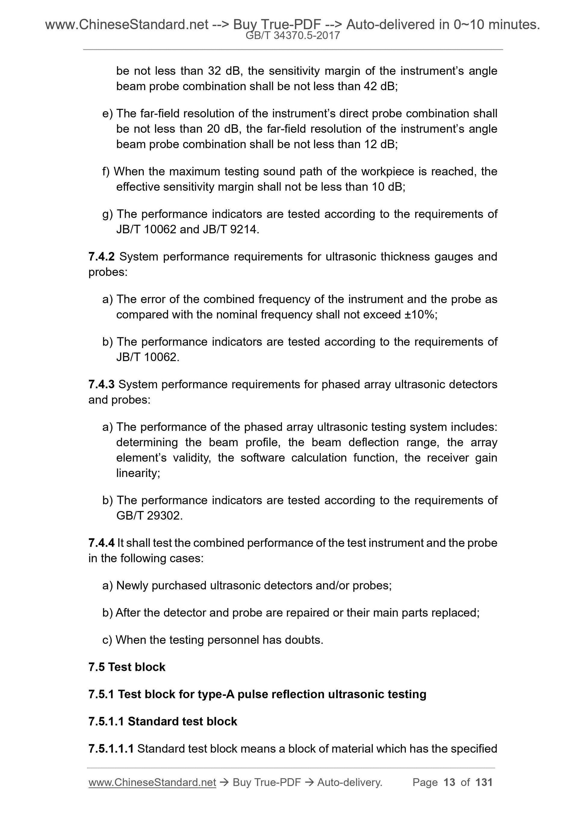
be not less than 32 dB, the sensitivity margin of the instrument’s angle
beam probe combination shall be not less than 42 dB;
e) The far-field resolution of the instrument’s direct probe combination shall
be not less than 20 dB, the far-field resolution of the instrument’s angle
beam probe combination shall be not less than 12 dB;
f) When the maximum testing sound path of the workpiece is reached, the
effective sensitivity margin shall not be less than 10 dB;
g) The performance indicators are tested according to the requirements of
JB/T 10062 and JB/T 9214.
7.4.2 System performance requirements for ultrasonic thickness gauges and
probes.
a) The error of the combined frequency of the instrument and the probe as
compared with the nominal frequency shall not exceed ±10%;
b) The performance indicators are tested according to the requirements of
JB/T 10062.
7.4.3 System performance requirements for phased array ultrasonic detectors
and probes.
a) The performance of the phased array ultrasonic testing system includes.
determining the beam profile, the beam deflection range, the array
element’s validity, the software calculation function, the receiver gain
linearity;
b) The performance indicators are tested according to the requirements of
GB/T 29302.
7.4.4 It shall test the combined performance of the test instrument and the probe
in the following cases.
a) Newly purchased ultrasonic detectors and/or probes;
b) After the detector and probe are repaired or their main parts replaced;
c) When the testing personnel has doubts.
7.5 Test block
7.5.1 Test block for type-A pulse reflection ultrasonic testing
7.5.1.1 Standard test block
7.5.1.1.1 Standard test block means a block of material which has the specified
7.6.1.1 Calibration, verification and intermediate verification shall be performed
on standard test blocks.
7.6.1.2 During calibration, verification and intermediate verification shall be
such that the main sound beam of the probe is vertically aligned with the
reflecting surface of the reflector, to obtain a stable and maximum reflected
signal.
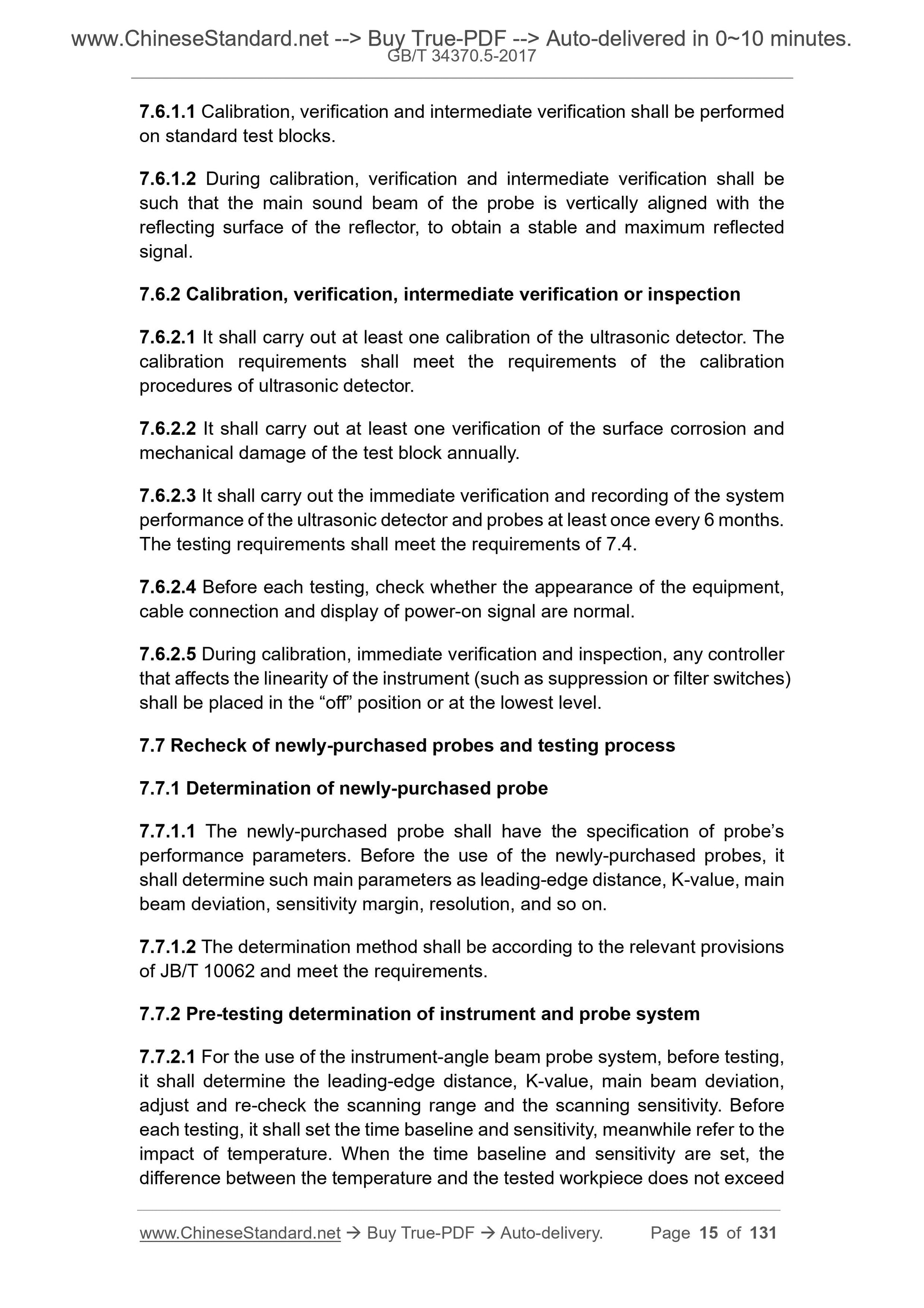
7.6.2 Calibration, verification, intermediate verification or inspection
7.6.2.1 It shall carry out at least one calibration of the ultrasonic detector. The
calibration requirements shall meet the requirements of the calibration
procedures of ultrasonic detector.
7.6.2.2 It shall carry out at least one verification of the surface corrosion and
mechanical damage of the test block annually.
7.6.2.3 It shall carry out the immediate verification and recording of the system
performance of the ultrasonic detector and probes at least once every 6 months.
The testing requirements shall meet the requirements of 7.4.
7.6.2.4 Before each testing, check whether the appearance of the equipment,
cable connection and display of power-on signal are normal.
7.6.2.5 During calibration, immediate verification and inspection, any controller
that affects the linearity of the instrument (such as suppression or filter switches)
shall be placed in the “off” position or at the lowest level.
7.7 Recheck of newly-purchased probes and testing process
7.7.1 Determination of newly-purchased probe
7.7.1.1 The newly-purchased probe shall have the specification of probe’s
performance parameters. Before the use of the newly-purchased probes, it
shall determine such main parameters as leading-edge distance, K-value, main
beam deviation, sensitivity margin, resolution, and so on.
7.7.1.2 The determination method shall be according to the relevant provisions
of JB/T 10062 and meet the requirements.
7.7.2 Pre-testing determination of instrument and probe system
7.7.2.1 For the use of the instrument-angle beam probe system, before testing,
it shall determine the leading-edge distance, K-value, main beam deviation,
adjust and re-check the scanning range and the scanning sensitivity. Before
each testing, it shall set the time baseline and sensitivity, meanwhile refer to the
impact of temperature. When the time baseline and sensitivity are set, the
difference between the temperature and the tested workpiece does not exceed
far as possible during the testing.
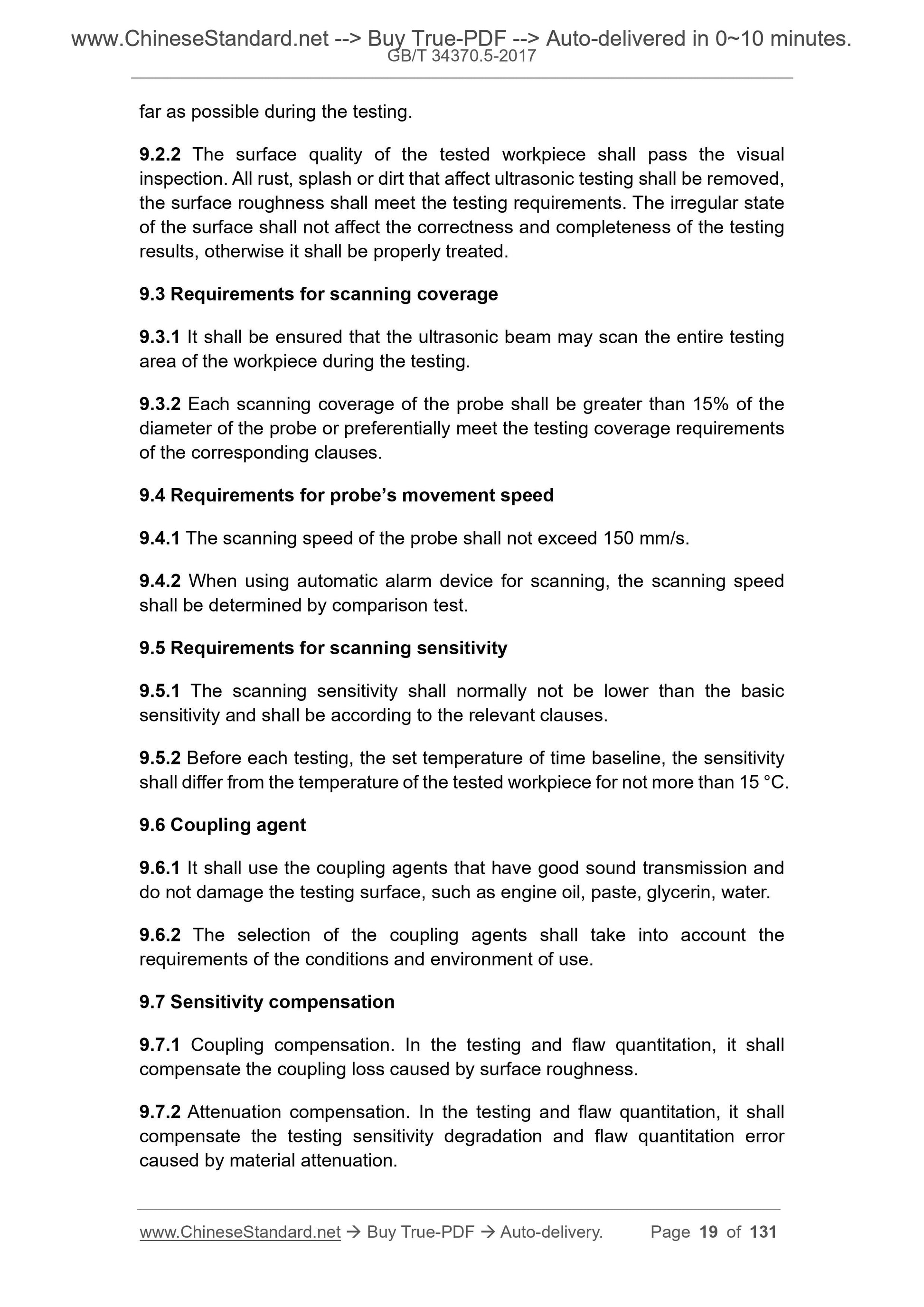
9.2.2 The surface quality of the tested workpiece shall pass the visual
inspection. All rust, splash or dirt that affect ultrasonic testing shall be removed,
the surface roughness shall meet the testing requirements. The irregular state
of the surface shall not affect the correctness and completeness of the testing
results, otherwise it shall be properly treated.
9.3 Requirements for scanning coverage
9.3.1 It shall be ensured that the ultrasonic beam may scan the entire testing
area of the workpiece during the testing.
9.3.2 Each scanning coverage of the probe shall be greater than 15% of the
diameter of the probe or preferentially meet the testing coverage requirements
of the corresponding clauses.
9.4 Requirements for probe’s movement speed
9.4.1 The scanning speed of the probe shall not exceed 150 mm/s.
9.4.2 When using automatic alarm device for scanning, the scanning speed
shall be determined by comparison test.
9.5 Requirements for scanning sensitivity
9.5.1 The scanning sensitivity shall normally not be lower than the basic
sensitivity and shall be according to the relevant clauses.
9.5.2 Before each testing, the set temperature of time baseline, the sensitivity
shall differ from the temperature of the tested workpiece for not more than 15 °C.
9.6 Coupling agent
9.6.1 It shall use the coupling agents that have good sound transmission and
do not damage the testing surface, such as engine oil, paste, glycerin, water.
9.6.2 The selection of the coupling agents shall take into account the
requirements of the conditions and environment of use.
9.7 Sensitivity compensation
9.7.1 Coupling compensation. In the testing and flaw quantitation, it shall
compensate the coupling loss caused by surface roughness.
9.7.2 Attenuation compensation. In the testing and flaw quantitation, it shall
compensate the testing sensitivity degradation and flaw quantitation error
caused by material attenuation.
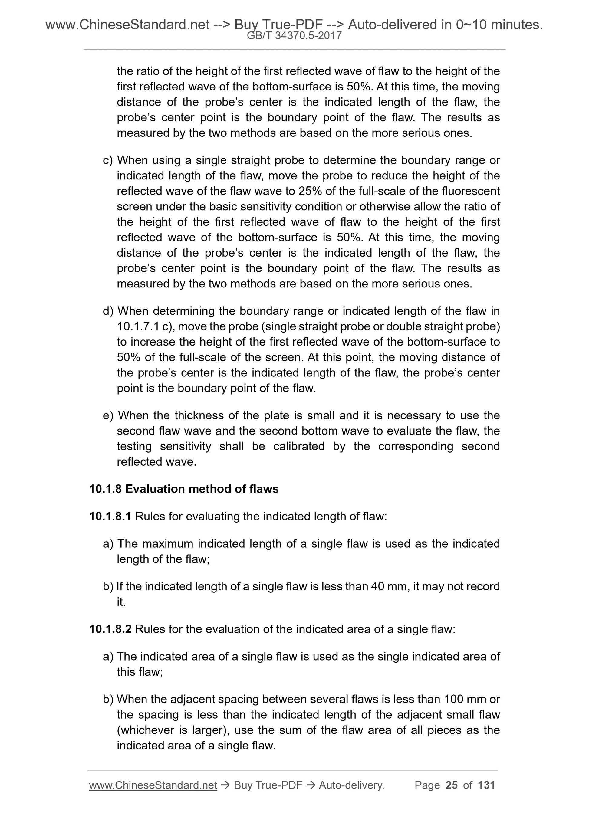
the ratio of the height of the first reflected wave of flaw to the height of the
first reflected wave of the bottom-surface is 50%. At this time, the moving
distance of the probe’s center is the indicated length of the flaw, the
probe’s center point is the boundary point of the flaw. The resu...
Share
