1
/
of
6
www.ChineseStandard.us -- Field Test Asia Pte. Ltd.
GB/T 34378-2017 English PDF (GB/T34378-2017)
GB/T 34378-2017 English PDF (GB/T34378-2017)
Regular price
$130.00
Regular price
Sale price
$130.00
Unit price
/
per
Shipping calculated at checkout.
Couldn't load pickup availability
GB/T 34378-2017: Dynamic balance test method for motorcycle tyres
Delivery: 9 seconds. Download (& Email) true-PDF + Invoice.
Get Quotation: Click GB/T 34378-2017 (Self-service in 1-minute)
Historical versions (Master-website): GB/T 34378-2017
Preview True-PDF (Reload/Scroll-down if blank)
GB/T 34378-2017
NATIONAL STANDARD OF THE
PEOPLE’S REPUBLIC OF CHINA
ICS 83.160.10
G 41
Dynamic balance test method for motorcycle tyres
ISSUED ON: SEPTEMBER 29, 2017
IMPLEMENTED ON: AUGUST 01, 2018
Issued by: General Administration of Quality Supervision, Inspection and
Quarantine;
Standardization Administration of the People's Republic of
China.
Table of Contents
Foreword ... 3
1 Scope ... 4
2 Normative references ... 4
3 Terms and definitions ... 4
4 Test equipment ... 9
5 Test conditions ... 10
6 Test steps ... 12
7 Test record ... 12
Dynamic balance test method for motorcycle tyres
1 Scope
This Standard specifies the terms and definitions, test equipment, test
conditions, test procedures and test records for motorcycle tyre dynamic
balance test.
This Standard applies to motorcycle tyres.
2 Normative references
The following documents are indispensable for the application of this document.
For dated references, only the dated version applies to this document. For
undated references, the latest edition (including all amendments) applies to this
document.
GB 518, Motorcycles tyres
GB/T 2983, Series of motorcycle tyres
GB/T 6326, Tyre terms and definitions
GB/T 6444, Mechanical vibration. Balancing. vocabulary
GB/T 13202, Series of motorcycle rims
GB/T 25158, Dynamic balancing machine for tyre
3 Terms and definitions
Terms and definitions determined by GB/T 6326 and GB/T 6444, and the
following ones are applicable to this document.
3.1 Static unbalance value
Product of the tyre mass multiplied by the center of gravity eccentricity.
Note 1: When the tyre rotates at a certain speed, the static unbalance produces
a force perpendicular to the axle. Calculate the static unbalance value
according to Formula (1):
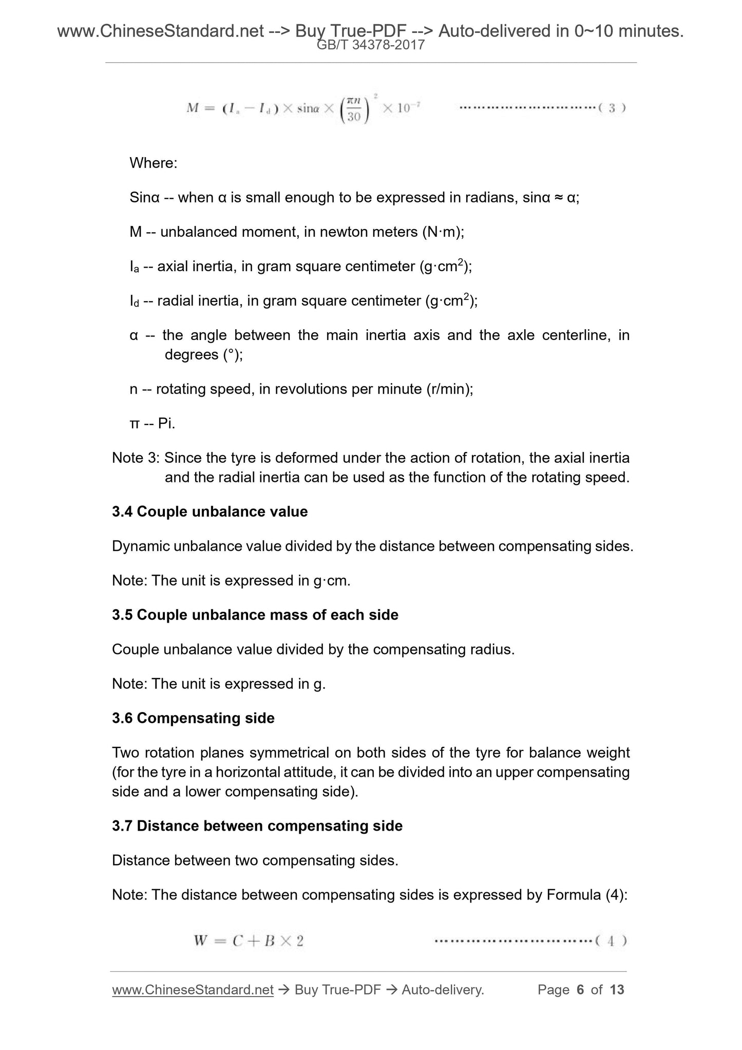
Where:
Sinα -- when α is small enough to be expressed in radians, sinα ≈ α;
M -- unbalanced moment, in newton meters (N·m);
Ia -- axial inertia, in gram square centimeter (g·cm2);
Id -- radial inertia, in gram square centimeter (g·cm2);
α -- the angle between the main inertia axis and the axle centerline, in
degrees (°);
n -- rotating speed, in revolutions per minute (r/min);
π -- Pi.
Note 3: Since the tyre is deformed under the action of rotation, the axial inertia
and the radial inertia can be used as the function of the rotating speed.
3.4 Couple unbalance value
Dynamic unbalance value divided by the distance between compensating sides.
Note: The unit is expressed in g·cm.
3.5 Couple unbalance mass of each side
Couple unbalance value divided by the compensating radius.
Note: The unit is expressed in g.
3.6 Compensating side
Two rotation planes symmetrical on both sides of the tyre for balance weight
(for the tyre in a horizontal attitude, it can be divided into an upper compensating
side and a lower compensating side).
3.7 Distance between compensating side
Distance between two compensating sides.
Note: The distance between compensating sides is expressed by Formula (4):
Us -- static unbalance value, in gram centimeter (g·cm);
Uc -- couple unbalance value, in gram centimeter (g·cm);
γs -- heavy point positioning angle of static unbalance, in degrees (°);
γc -- heavy point positioning angle of couple unbalance, in degrees (°);
R -- compensating radius, in centimeters (cm).
3.10 Heavy point positioning angle
The circumferential angle BETWEEN the heavy point which produces
unbalance AND the specified reference point.
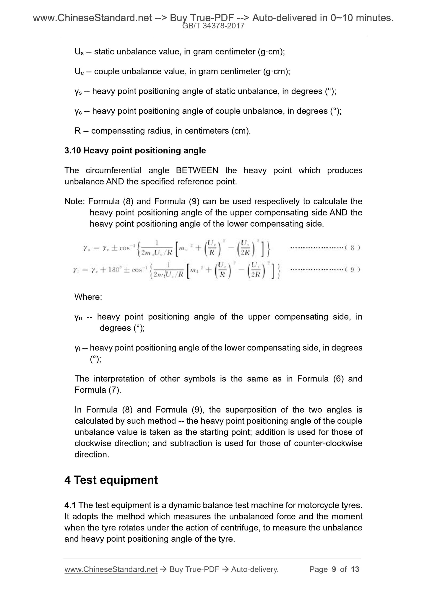
Note: Formula (8) and Formula (9) can be used respectively to calculate the
heavy point positioning angle of the upper compensating side AND the
heavy point positioning angle of the lower compensating side.
Where:
γu -- heavy point positioning angle of the upper compensating side, in
degrees (°);
γl -- heavy point positioning angle of the lower compensating side, in degrees
(°);
The interpretation of other symbols is the same as in Formula (6) and
Formula (7).
In Formula (8) and Formula (9), the superposition of the two angles is
calculated by such method -- the heavy point positioning angle of the couple
unbalance value is taken as the starting point; addition is used for those of
clockwise direction; and subtraction is used for those of counter-clockwise
direction.
4 Test equipment
4.1 The test equipment is a dynamic balance test machine for motorcycle tyres.
It adopts the method which measures the unbalanced force and the moment
when the tyre rotates under the action of centrifuge, to measure the unbalance
and heavy point positioning angle of the tyre.
minimum value; take the minimum value).
5.3.2 The calibration diameter of the rim in the test shall comply with the
provisions of GB/T 13202. However, in order to facilitate loading and unloading
and to properly position the tyre bead, the calibration diameter of the test rim
may be slightly smaller than the calibration diameter of the measuring rim, and
the difference shall not be greater than 1.2 mm.
5.3.3 Before the test, the unbalance and heavy point positioning angle of the
rim and axle assembly in the test shall be measured on the test machine.
5.3.4 In order to ensure that the tyre is properly seated on the test rim, the
surface of the tyre bead or the rim bead seat or both may be evenly coated with
a suitable lubricant.
5.4 Test pressure
The test pressure of the motorcycle tyre is 250 kPa, and the allowable deviation
of the test pressure shall be within ±50 kPa.
6 Test steps
6.1 Set tyre unbalance compensating radius and distance between
compensating side for the test machine.
6.2 Mount the tyre on the dynamic balance test machine; inflate the tyre so that
the tyre can fully expand and properly seat on the rim; then adjust to the test
pressure specified in 5.4.
6.3 Make the tyre rotate at a speed that is determined by the equipment provider
within the range that is specified in 4.2, so to measure the static unbalance
value and couple unbalance value along the circumference of the tyre.
6.4 Subtract the unbalanced amount of the rim and the axle assembly from the
measured value, and the maximum difference is the tyre's static unbalance
value and couple unbalance value. The position of the maximum value on the
circumference of the tyre is the heavy point positioning angle of above two
unbalanced values, respectively.
6.5 Stop the tyre from rotating. Print a light dot mark on the sidewall of the tyre
as needed.
7 Test record
The following parameters shall be recorded after the test:
Share
