NaN
/
of
-Infinity
PayPal, credit cards. Download editable-PDF and invoice in 1 second!
GB/T 34601-2017 English PDF (GBT34601-2017)
GB/T 34601-2017 English PDF (GBT34601-2017)
Regular price
$90.00 USD
Regular price
Sale price
$90.00 USD
Unit price
/
per
Shipping calculated at checkout.
Couldn't load pickup availability
Delivery: 3 seconds. Download true-PDF + Invoice.
Get QUOTATION in 1-minute: Click GB/T 34601-2017
Historical versions: GB/T 34601-2017
Preview True-PDF (Reload/Scroll if blank)
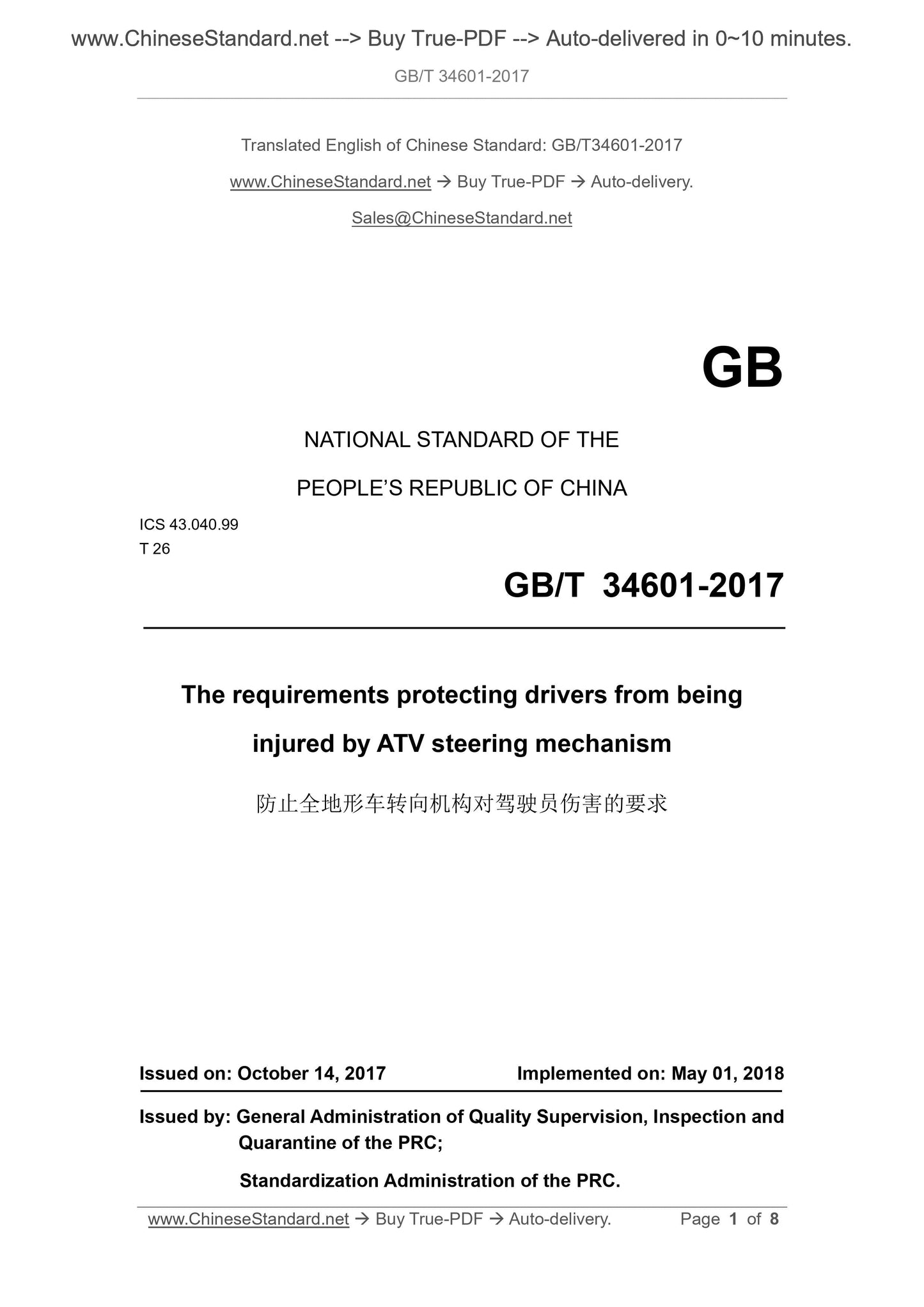
GB/T 34601-2017: The requirements protecting drivers from being injured by ATV steering mechanism
GB/T 34601-2017
GB
NATIONAL STANDARD OF THE
PEOPLE’S REPUBLIC OF CHINA
ICS 43.040.99
T 26
The requirements protecting drivers from being
injured by ATV steering mechanism
ISSUED ON. OCTOBER 14, 2017
IMPLEMENTED ON. MAY 01, 2018
Issued by. General Administration of Quality Supervision, Inspection and
Quarantine of the PRC;
Standardization Administration of the PRC.
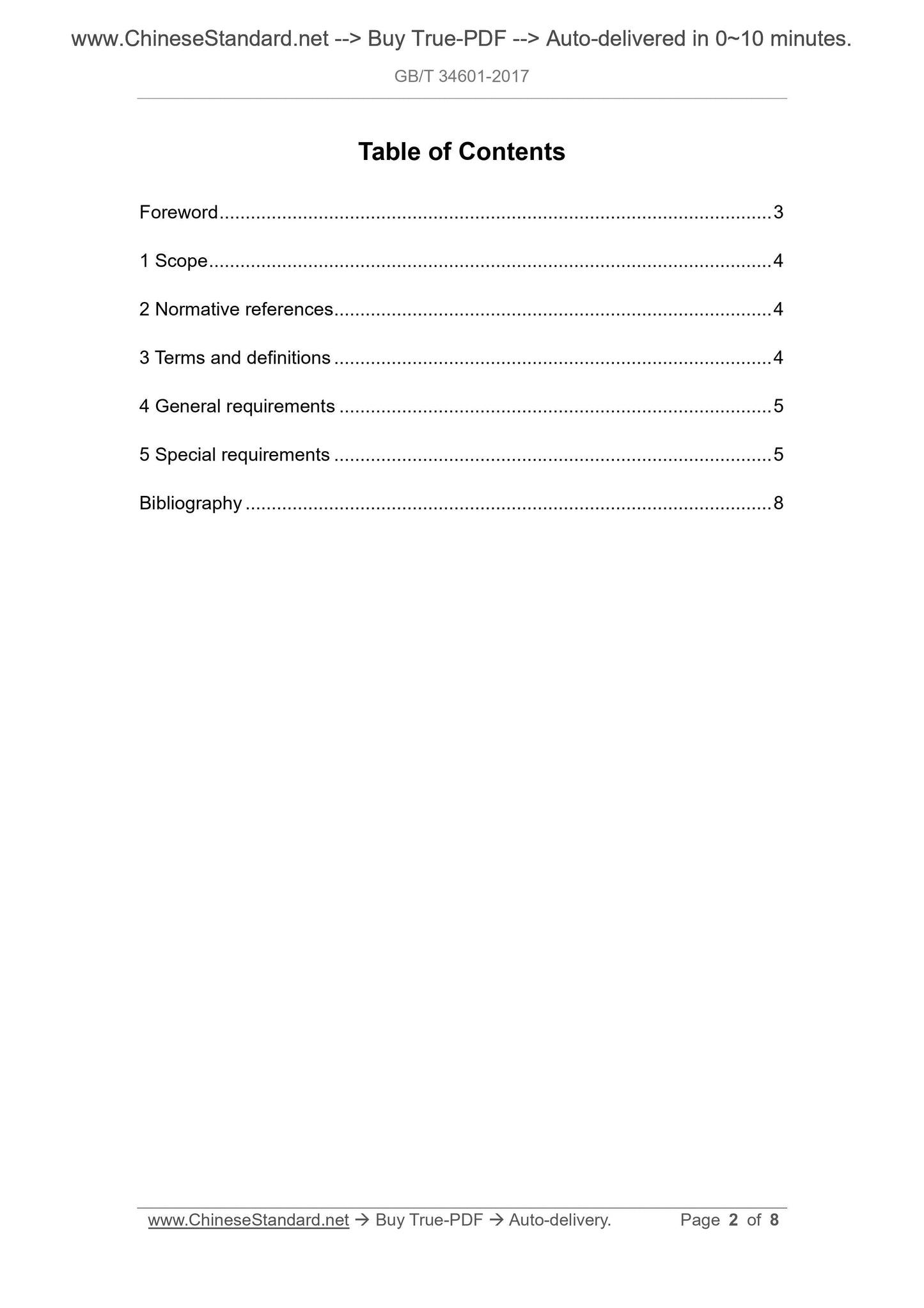
Table of Contents
Foreword ... 3
1 Scope ... 4
2 Normative references ... 4
3 Terms and definitions ... 4
4 General requirements ... 5
5 Special requirements ... 5
Bibliography ... 8
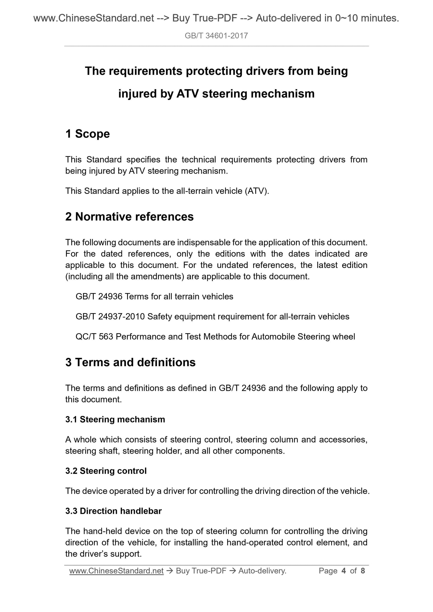
The requirements protecting drivers from being
injured by ATV steering mechanism
1 Scope
This Standard specifies the technical requirements protecting drivers from
being injured by ATV steering mechanism.
This Standard applies to the all-terrain vehicle (ATV).
2 Normative references
The following documents are indispensable for the application of this document.
For the dated references, only the editions with the dates indicated are
applicable to this document. For the undated references, the latest edition
(including all the amendments) are applicable to this document.
GB/T 24936 Terms for all terrain vehicles
GB/T 24937-2010 Safety equipment requirement for all-terrain vehicles
QC/T 563 Performance and Test Methods for Automobile Steering wheel
3 Terms and definitions
The terms and definitions as defined in GB/T 24936 and the following apply to
this document.
3.1 Steering mechanism
A whole which consists of steering control, steering column and accessories,
steering shaft, steering holder, and all other components.
3.2 Steering control
The device operated by a driver for controlling the driving direction of the vehicle.
3.3 Direction handlebar
The hand-held device on the top of steering column for controlling the driving
direction of the vehicle, for installing the hand-operated control element, and
the driver’s support.
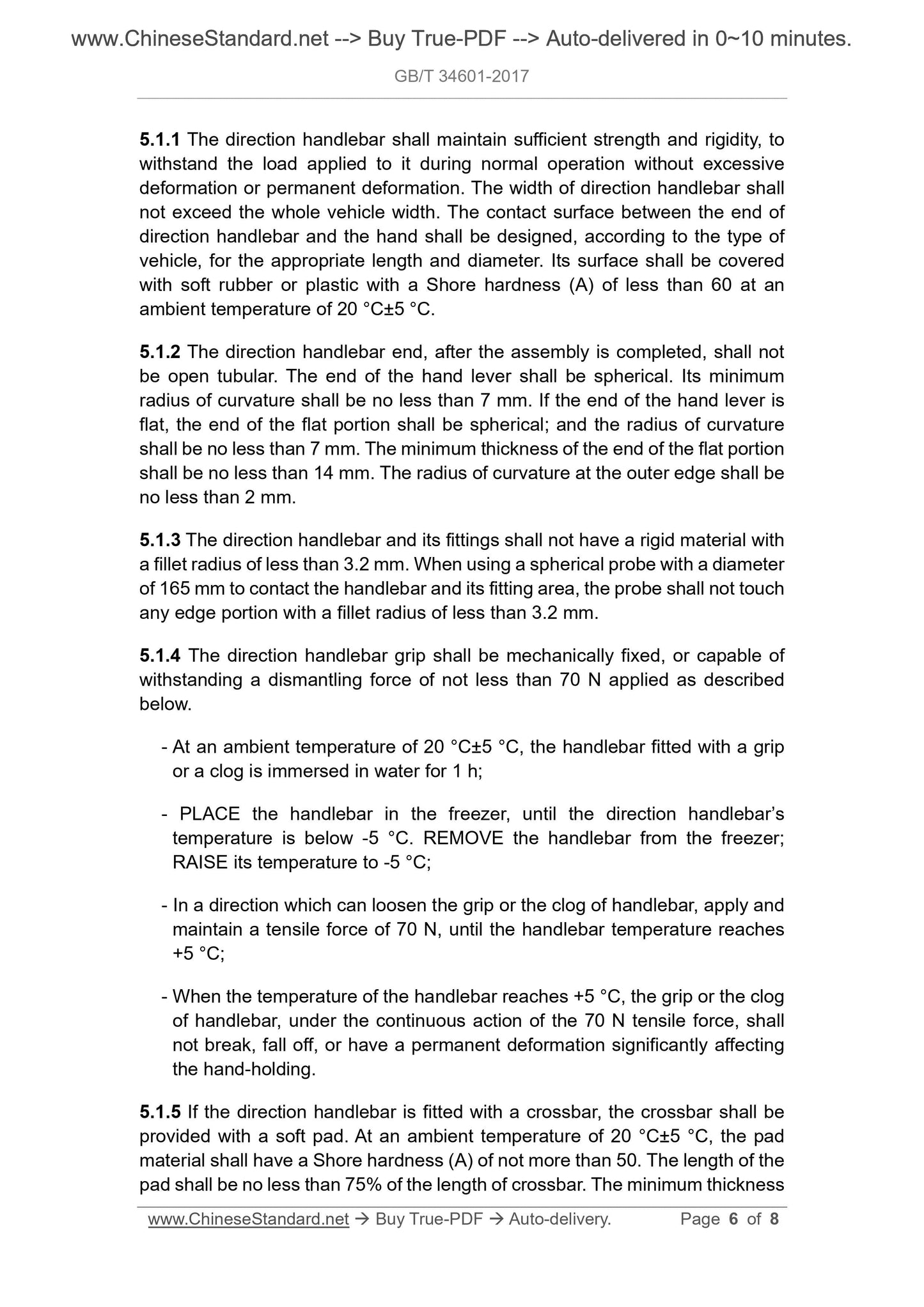
5.1.1 The direction handlebar shall maintain sufficient strength and rigidity, to
withstand the load applied to it during normal operation without excessive
deformation or permanent deformation. The width of direction handlebar shall
not exceed the whole vehicle width. The contact surface between the end of
direction handlebar and the hand shall be designed, according to the type of
vehicle, for the appropriate length and diameter. Its surface shall be covered
with soft rubber or plastic with a Shore hardness (A) of less than 60 at an
ambient temperature of 20 °C±5 °C.
5.1.2 The direction handlebar end, after the assembly is completed, shall not
be open tubular. The end of the hand lever shall be spherical. Its minimum
radius of curvature shall be no less than 7 mm. If the end of the hand lever is
flat, the end of the flat portion shall be spherical; and the radius of curvature
shall be no less than 7 mm. The minimum thickness of the end of the flat portion
shall be no less than 14 mm. The radius of curvature at the outer edge shall be
no less than 2 mm.
5.1.3 The direction handlebar and its fittings shall not have a rigid material with
a fillet radius of less than 3.2 mm. When using a spherical probe with a diameter
of 165 mm to contact the handlebar and its fitting area, the probe shall not touch
any edge portion with a fillet radius of less than 3.2 mm.
5.1.4 The direction handlebar grip shall be mechanically fixed, or capable of
withstanding a dismantling force of not less than 70 N applied as described
below.
- At an ambient temperature of 20 °C±5 °C, the handlebar fitted with a grip
or a clog is immersed in water for 1 h;
- PLACE the handlebar in the freezer, until the direction handlebar’s
temperature is below -5 °C. REMOVE the handlebar from the freezer;
RAISE its temperature to -5 °C;
- In a direction which can loosen the grip or the clog of handlebar, apply and
maintain a tensile force of 70 N, until the handlebar temperature reaches
+5 °C;
- When the temperature of the handlebar reaches +5 °C, the grip or the clog
of handlebar, under the continuous action of the 70 N tensile force, shall
not break, fall off, or have a permanent deformation significantly affecting
the hand-holding.
5.1.5 If the direction handlebar is fitted with a crossbar, the crossbar shall be
provided with a soft pad. At an ambient temperature of 20 °C±5 °C, the pad
material shall have a Shore hardness (A) of not more than 50. The length of the
pad shall be no less than 75% of the length of crossbar. The minimum thickness


