1
/
of
10
www.ChineseStandard.us -- Field Test Asia Pte. Ltd.
GB/T 37337-2019 English PDF (GB/T37337-2019)
GB/T 37337-2019 English PDF (GB/T37337-2019)
Regular price
$145.00
Regular price
Sale price
$145.00
Unit price
/
per
Shipping calculated at checkout.
Couldn't load pickup availability
GB/T 37337-2019: Protection of the occupants in the event of a lateral pole collision
Delivery: 9 seconds. Download (& Email) true-PDF + Invoice.
Get Quotation: Click GB/T 37337-2019 (Self-service in 1-minute)
Historical versions (Master-website): GB/T 37337-2019
Preview True-PDF (Reload/Scroll-down if blank)
GB/T 37337-2019
NATIONAL STANDARD OF THE
PEOPLE’S REPUBLIC OF CHINA
ICS 43.020
T 09
Protection of the occupants in the event
of a lateral pole collision
ISSUED ON: MARCH 25, 2019
IMPLEMENTED ON: OCTOBER 01, 2019
Issued by: State Administration for Market Regulation;
Standardization Administration of the PRC.
Table of Contents
Foreword ... 3
1 Scope ... 4
2 Normative references ... 4
3 Terms and definitions ... 4
4 Technical requirements ... 9
5 Test methods ... 11
6 Change of vehicle type ... 16
Appendix A (Normative) WorldSID 50th dummy technical regulations and
placement procedures ... 18
Appendix B (Normative) ES2-re dummy technical regulations and placement
procedures ... 20
Protection of the occupants in the event
of a lateral pole collision
1 Scope
This Standard specifies the technical requirements and test methods for the
protection of the occupants in the event of a lateral pole collision.
This Standard applies to type M1 automobiles.
2 Normative references
The following documents are indispensable for the application of this document.
For the dated references, only the editions with the dates indicated are
applicable to this document. For the undated references, the latest edition
(including all the amendments) are applicable to this document.
GB 14166 Safety-belts, restraint systems, child restraint systems and
ISOFIX child restraint systems for occupants of power-driven vehicles
GB 14167 Safety-belt anchorages, ISOFIX anchorages systems and ISOFIX
top tether anchorages for vehicles
ISO 6487 Road vehicles - Measurement techniques in impact tests -
Instrumentation
3 Terms and definitions
The following terms and definitions apply to this document.
3.1 Vehicle type
Motor vehicle types which do not differ in the following main aspects:
a) The length and width of the vehicle which adversely affect the performance
specified in this Standard;
b) The structure, dimensions, contours, and materials of the side walls of
passenger compartment which adversely affect the performance specified
in this Standard;
capacity; and the engine oil and other liquids are at the highest level, with
suitable on-board tools and spare tire.
3.8 Rated cargo and luggage mass
Maximum allowable total mass subtracts the unladen mass and the rated
occupant mass.
Note: The rated occupant mass is the rated number of passengers multiplied by 68 kg.
3.9 Reference mass
The vehicle’s unladen mass plus the mass of side impact dummy and 136 kg
or rated cargo and luggage mass (whichever is less).
Note: The side impact dummy (or equivalent mass) is placed in the front seat position on
the impact side. The 136 kg load or rated cargo and luggage are placed at the center
of the trunk carrying area and corresponding to the longitudinal centerline of the
vehicle.
3.10 Back door
A door (or door system) at the rear of vehicle used for occupant entry-exit or
cargo loading-unloading. But it does not include the trunk, and the door (or
window) which is completely made of glass material and whose door-lock
system is directly connected to the glass material.
3.11 Latch
A part mounted within the door and engaged with a striker on the door post to
hold the door in the latched position.
3.12 Striker
A part mounted on the door pillar and engaged with the latch to hold the door
in the latched position.
3.13 Door hinges
An assembly of parts which are coupled to the vehicle door and the body and
rotatable about the same axis and coupled to each other.
3.14 Fully latched position
The position at which the latch and the striker are engaged when the door is
completely closed.
3.15 Secondary latched position
3.23 Impact rigid pole
A vertical, non-deformable rigid metal structure.
Note: The lower end cannot be higher than 102 mm above the lowest point of the vehicle’s
impact side tire under the reference attitude. The upper end extends at least above
the highest point of the test vehicle ceiling. The pole has a diameter of 254 mm±6
mm and is separated from the surface of the support frame. Within 100 ms of the
start of contact between the vehicle and the rigid pole, it does not come into contact
with the surface of the support frame.
3.24 Impact velocity vector
The geometric quantity which describes the velocity and direction of vehicle
motion when the vehicle collides with a rigid pole. The impact velocity vector
points to the direction of motion of the vehicle. The starting point is the center
of gravity of the vehicle. The magnitude represents the impact velocity of the
vehicle.
3.25 Vehicle reference coordinate system
Right angle orthogonal coordinate system, including three coordinate axes,
longitudinal axis (X), lateral axis (Y), and vertical axis (Z). X and Y are in the
same horizontal plane. Z passes the intersection of X and Y.
3.26 Seat cushion reference point
A reference point for the longitudinal (front-rear) and vertical position stroke
adjustment of adjustable seat cushion, which is located outside the seat
cushion support structure.
3.27 Seat cushion reference line
A plane curve on the outer surface of seat cushion passing through the seat
cushion reference point. Its projection in the longitudinal mid-perpendicular
plane of the vehicle is a straight line, which is at an angle to the horizontal plane.
3.28 Seat cushion reference line angle
The angle at which the projection of the seat cushion reference line in the
longitudinal mid-perpendicular plane of the vehicle is relative to the horizontal
plane (or horizontal reference plane).
4 Technical requirements
4.1 General requirements
b) The latch and the striker cannot be separated. The parts of hinges cannot
be separated from each other or from the vehicle joint;
c) Neither the latch nor the door hinges device can be pulled out of the joint.
4.3.2 In the impact test, if there is liquid leakage in the fuel supply system, within
the first 5 min after the vehicle starts to contact the rigid pole, the leakage
amount is not more than 142 g. Within the next 25 min, the leakage rate is not
more than 28 g/min.
5 Test methods
5.1 Test site
The test site shall be large enough to accommodate the installation of test
equipment including the test vehicle-mounted platform drive system. The
ground of the site where the vehicles collide and move shall be level, flat, and
dry.
5.2 Test conditions
5.2.1 Unless otherwise specified in this Standard, the instrumentation shall
comply with the provisions of ISO 6487.
5.2.2 During side impact, the temperature of the WorldSID 50th dummy shall be
stable between 20.6 °C~22.2 °C; the temperature of the ES2-re dummy shall
be stable between 18 °C~26 °C.
5.2.3 From the direction of vehicle motion, during the impact test, the impact
reference line shall be aligned with the surface centerline of rigid pole. When
the vehicle collides with the rigid pole, the surface centerline of the rigid pole
shall be controlled in a contact area, which is parallel to the impact reference
line and formed by two perpendicular planes respectively 25 mm from the
impact reference line.
5.2.4 In the driving process of the test vehicle, during the acceleration phase
before the first contact with the rigid pole, the acceleration shall not exceed 1.5
m/s2.
5.3 Test velocity
At the moment of impact, the impact velocity of vehicle shall be 3201 km/h (But
for vehicles with a width of not more than 1.5 m, the velocity can be reduced to
carry out the corresponding test. The impact velocity shall be 2601 km/h). This
5.5.2.2 The fuel tank can be filled with water. The mass of the water filled is 90%
of the mass of the full oil specified by the manufacturer.
5.5.2.3 All other systems (brake system, lubrication system, cooling system,
etc.) can be emptied. The mass of the excluded liquid shall be compensated.
5.5.3 Vehicle attitude
5.5.3.1 Under the test attitude, the left and right pitch angles of vehicle shall be
between the range of the pitch angle of the vehicle on the corresponding side
under the unladen attitude and under the reference attitude respectively.
5.5.3.2 Each straight line, used to determine the left (or right) pitch angle of the
vehicle under the unladen attitude, the reference attitude, and the test attitude,
shall be connected using the same reference point on the same side doorsill.
5.5.3.3 Under the test attitude, the front and rear roll angles of vehicle shall be
between the range of the roll angle of the vehicle on the corresponding side
under the unladen attitude and under the reference attitude respectively.
5.5.3.4 Each straight line, used to determine the front (or rear) roll angle of the
vehicle under the unladen attitude, the reference attitude, and the test attitude,
shall be connected using the same reference point at the front (or rear) of the
vehicle body.
5.6 Vehicle preparation
5.6.1 The impact side window is closed. The sunroof is in a fully closed position.
5.6.2 For vehicles with foldable roofs, including convertible cars, the roof shall
be placed in such a position that a closed passenger compartment can be
formed.
5.6.3 The door shall be closed but not locked. For vehicles with automatic lock-
up system, all doors, before impact, shall be locked. For vehicles in which the
automatic lock-up system is an optional or the driver can close the system, at
least the non-impact side door is locked before the impact.
5.6.4 For automatic transmission vehicles, the shift lever is in the neutral
position. For manual transmission vehicles, it is in the second gear position.
The parking brake is in the braking state.
5.6.5 The seat comfort adjustment system shall be in the lowest or unexpanded
position. Such as the seat lumbar support system, it shall be at the lowest,
retracted, or exhaust-air adjustment position. The seat cushion length
adjustable system and the leg support system shall be adjusted to the last or
5.7 Side impact dummy and its placement
5.7.1 The side impact dummy shall comply with the provisions of Appendix A or
Appendix B. As specified in the appendix, it shall be placed on the outer seat
on the front row of the impact side.
5.7.2 The dummy wears a safety-belt or other restraint systems selected for the
vehicle type. Safety-belts and safety-belt anchorages shall comply with the
provisions of GB 14166 and GB 14167.
5.7.3 The safety-belt or restraint system worn by the dummy shall, according to
the manufacturer’s specifications, be adjusted to fit the dummy. If the
manufacturer does not specify, for the height direction, it shall be adjusted to
the middle position. If it is not possible, it shall be adjusted to the nearest middle-
lower position.
5.8 Determination of dummy parameters
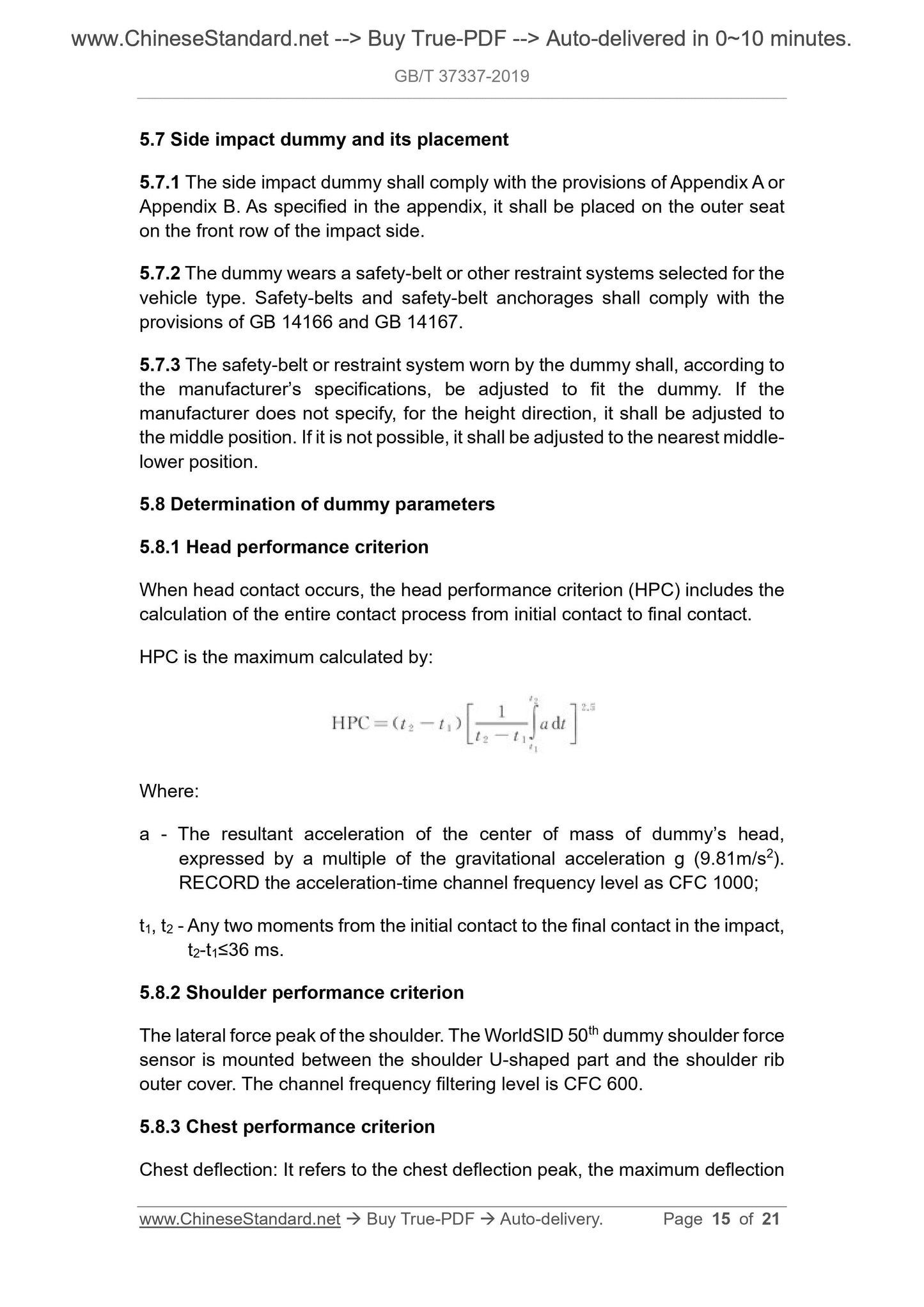
5.8.1 Head performance criterion
When head contact occurs, the head performance criterion (HPC) includes the
calculation of the entire contact process from initial contact to final contact.
HPC is the maximum calculated by:
Where:
a - The resultant acceleration of the center of mass of dummy’s head,
expressed by a multiple of the gravitational acceleration g (9.81m/s2).
RECORD the acceleration-time channel frequency level as CFC 1000;
t1, t2 - Any two moments from the initial contact to the final contact in the impact,
t2-t1≤36 ms.
5.8.2 Shoulder performance criterion
The lateral force peak of the shoulder. The WorldSID 50th dummy shoulder force
sensor is mounted between the shoulder U-shaped part and the shoulder rib
outer cover. The channel frequency filtering level is CFC 600.
5.8.3 Chest performance criterion
Chest deflection: It refers to the chest deflection peak, the maximum deflection
Appendix A
(Normative)
WorldSID 50th dummy technical regulations and placement procedures
A.1 Overview
A.1.1 The side impact dummy WorldSID 50th specified in this appendix is a new,
highly-simulated global unified side impact dummy, representing the 50th
percentile adult male.
A.1.2 Detailed instructions and technical drawings of the dummy construction,
assembly, adjustment, and calibration procedures can be found in the user
manual.
A.2 Placement of WorldSID 50th dummy
A.2.1 CHECK the direction of the impact applicable to the dummy.
A.2.2 In accordance with the side impact test procedure, the dummy is placed
on the outer seat on the front row of the impact side.
A.2.3 The symmetrical center plane of the dummy coincides with the vertical
center plane of the seat at the specified position. The dummy’s upper torso
rests on the seat back.
A.2.4 On the seat, by swinging the dummy back and forth and laterally, adjust
the pelvic backward position.
A.2.5 The lower abdomen rib shall be located behind the internal abdominal
wall of pelvic muscle.
A.2.6 The correct position of the dummy pelvis is determined by the relative
position OF the H point on both sides of the WorldSID 50th dummy pelvis WITH
the H point of the H-point device. The determination procedure is as follows:
- The straight line passing through the H point of the dummy shall be level.
The error shall not exceed ±2°. The H point of the WorldSID 50th dummy
shall be 20 mm longitudinally forward of the H point of the H-point device,
with an error range of ±10 mm.
- If the dummy’s knee touches the instrument board, and the seat cannot be
adjusted to the test position, adjust the seat position backwards, until at
least 5 mm of clearance is left in the knee; and CORRECT the H point target
Appendix B
(Normative)
ES2-re dummy technical regulations and placement procedures
B.1 Overview
B.1.1 The side impact dummy ES-2re [Translator note: this is slightly different
from “ES2-re”. Hereafter the same. Typo of original text?] specified in this
appendix is an improved type of the Euro SID II dummy. On the basis of the
dummy, the rib structure is adjusted; and the rib extension device is added.
B.1.2 Detailed instructions and technical drawings of the ...
Share
