1
/
of
8
PayPal, credit cards. Download editable-PDF & invoice in 1 second!
GB/T 40237-2021 English PDF (GBT40237-2021)
GB/T 40237-2021 English PDF (GBT40237-2021)
Regular price
$170.00 USD
Regular price
Sale price
$170.00 USD
Unit price
/
per
Shipping calculated at checkout.
Couldn't load pickup availability
Delivery: 3 seconds. Download true-PDF + Invoice.
Get QUOTATION in 1-minute: Click GB/T 40237-2021
Historical versions: GB/T 40237-2021
Preview True-PDF (Reload/Scroll if blank)
GB/T 40237-2021: Test method for ignitability of foamed plastic - Welding spark method
GB/T 40237-2021
GB
NATIONAL STANDARD OF THE
PEOPLE’S REPUBLIC OF CHINA
ICS 13.220.40
CCS C 80
Test method for ignitability of foamed plastic -
Welding spark method
ISSUED ON: MAY 21, 2021
IMPLEMENTED ON: DECEMBER 01, 2021
Issued by: State Administration for Market Regulation;
Standardization Administration of the People’s Republic of
China.
Table of Contents
Foreword ... 3
1 Scope ... 4
2 Normative references ... 4
3 Terms and definitions ... 4
4 Test principle ... 5
5 Instruments and apparatuses ... 5
6 Test sample ... 10
7 Conditioning ... 11
8 Test procedure ... 11
9 Optional procedures ... 13
10 Test result judgments ... 14
11 Safety protection ... 14
12 Test report ... 15
Test method for ignitability of foamed plastic -
Welding spark method
1 Scope
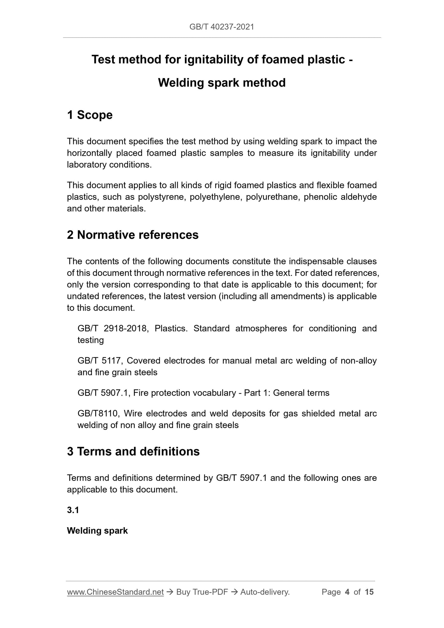
This document specifies the test method by using welding spark to impact the
horizontally placed foamed plastic samples to measure its ignitability under
laboratory conditions.
This document applies to all kinds of rigid foamed plastics and flexible foamed
plastics, such as polystyrene, polyethylene, polyurethane, phenolic aldehyde
and other materials.
2 Normative references
The contents of the following documents constitute the indispensable clauses
of this document through normative references in the text. For dated references,
only the version corresponding to that date is applicable to this document; for
undated references, the latest version (including all amendments) is applicable
to this document.
GB/T 2918-2018, Plastics. Standard atmospheres for conditioning and
testing
GB/T 5117, Covered electrodes for manual metal arc welding of non-alloy
and fine grain steels
GB/T 5907.1, Fire protection vocabulary - Part 1: General terms
GB/T8110, Wire electrodes and weld deposits for gas shielded metal arc
welding of non alloy and fine grain steels
3 Terms and definitions
Terms and definitions determined by GB/T 5907.1 and the following ones are
applicable to this document.
3.1
Welding spark
20 – electric welding ignition system.
Figure 1 – Schematic diagram of the electric welding spark test device
5.2 Combustion box
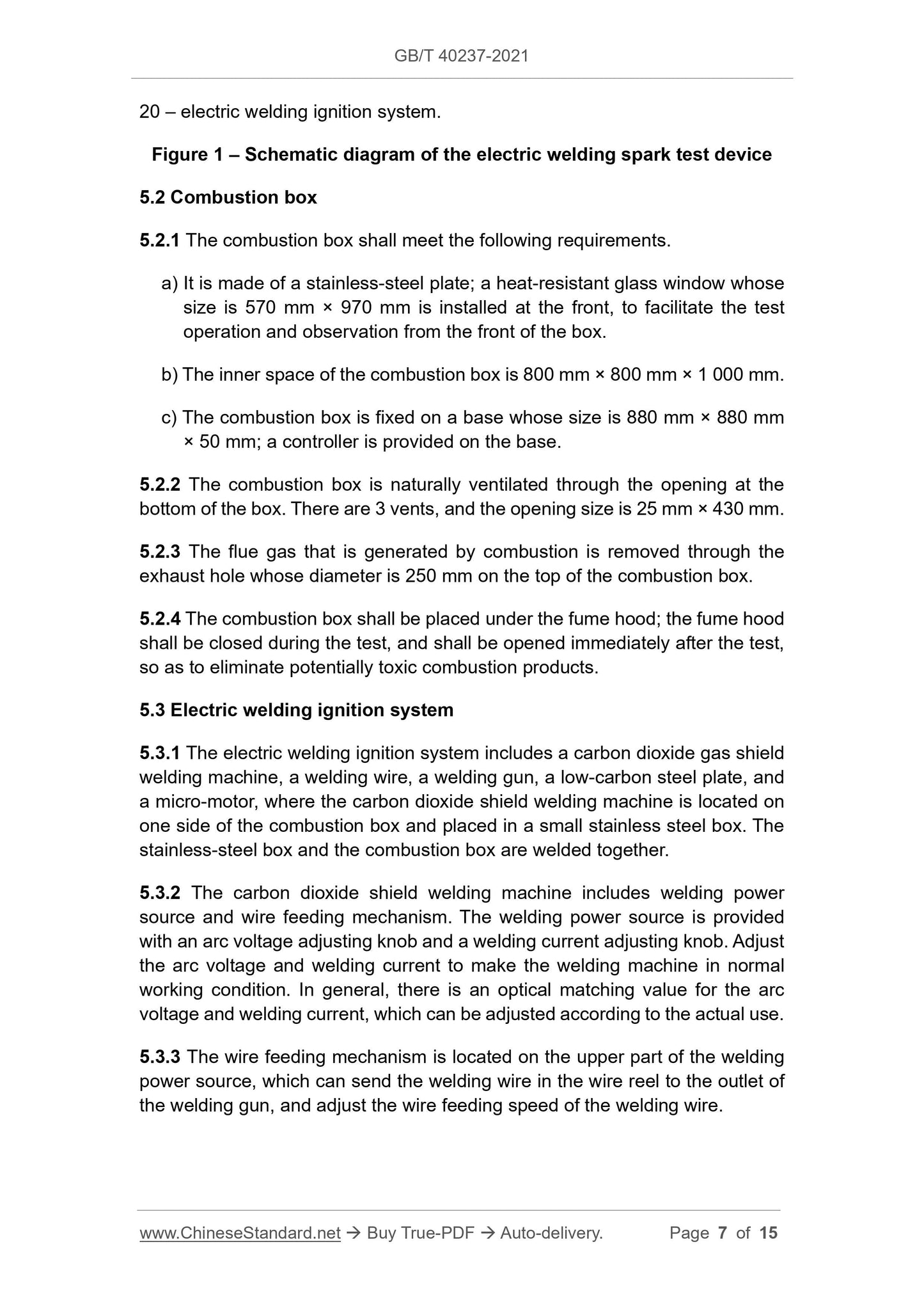
5.2.1 The combustion box shall meet the following requirements.
a) It is made of a stainless-steel plate; a heat-resistant glass window whose
size is 570 mm × 970 mm is installed at the front, to facilitate the test
operation and observation from the front of the box.
b) The inner space of the combustion box is 800 mm × 800 mm × 1 000 mm.
c) The combustion box is fixed on a base whose size is 880 mm × 880 mm
× 50 mm; a controller is provided on the base.
5.2.2 The combustion box is naturally ventilated through the opening at the
bottom of the box. There are 3 vents, and the opening size is 25 mm × 430 mm.
5.2.3 The flue gas that is generated by combustion is removed through the
exhaust hole whose diameter is 250 mm on the top of the combustion box.
5.2.4 The combustion box shall be placed under the fume hood; the fume hood
shall be closed during the test, and shall be opened immediately after the test,
so as to eliminate potentially toxic combustion products.
5.3 Electric welding ignition system
5.3.1 The electric welding ignition system includes a carbon dioxide gas shield
welding machine, a welding wire, a welding gun, a low-carbon steel plate, and
a micro-motor, where the carbon dioxide shield welding machine is located on
one side of the combustion box and placed in a small stainless steel box. The
stainless-steel box and the combustion box are welded together.
5.3.2 The carbon dioxide shield welding machine includes welding power
source and wire feeding mechanism. The welding power source is provided
with an arc voltage adjusting knob and a welding current adjusting knob. Adjust
the arc voltage and welding current to make the welding machine in normal
working condition. In general, there is an optical matching value for the arc
voltage and welding current, which can be adjusted according to the actual use.
5.3.3 The wire feeding mechanism is located on the upper part of the welding
power source, which can send the welding wire in the wire reel to the outlet of
the welding gun, and adjust the wire feeding speed of the welding wire.
5.3.4 This test method uses ER50 rolled carbon steel welding wire whose
diameter is 1.0 mm. The material and performance of the welding wire shall
meet the requirements of the standard GB/T 8110.
5.3.5 The welding gun is connected to the positive electrode of the welding
power source and shall meet the following requirements.
a) The welding gun passes through the opening on the side wall of the box
and is placed on the upper part of the combustion box.
b) The welding gun can adjust the extension length of the welding wire. The
extension length of the welding wire is usually about 10 times the diameter
of the welding wire.
c) The welding gun uses the heat that is generated by the high current and
high voltage of the carbon dioxide shield welding machine to gather at the
welding gun terminal to melt the welding wire.
5.3.6 The low carbon steel plate, which is used as the base material to simulate
the welded workpiece, shall meet the following requirements.
a) The low carbon steel plate is connected to the negative electrode of the
welding power source.
b) The low carbon steel plate is located directly above the welding gun; the
size is 250 mm × 150 mm × 10 mm.
c) The low carbon steel plate is fixed on the metal clip of the micro motor
through the screw holes on the four corners; the micro motor drives the
movement of the low carbon steel plate.
d) During the test, the low carbon steel plate moves at a constant speed
relative to the welding gun.
5.3.7 There are two micro motors that control the operation of the low carbon
steel plate; one controls its left and right movement, and the other controls its
forward and backward movement. The following requirements shall be met
during operation.
a) First, a micro motor drives the low carbon steel plate to run from the left
end to the right end; then, another micro motor drives it to change the line,
so that the low carbon steel plate runs from the right end to the left end;
then, it changes to another line and runs line by line.
b) The motion trajectory that is formed by the welding wire on the low carbon
steel plate is shown in Figure 2.
5.4.4 The timing device can continuously record the test time and display it to
the second with an accuracy of 1 s.
5.5 Sample holder
5.5.1 The sample holder is a square stainless steel frame slot, whose size is
610 mm × 610 mm. The steel wire grid is located in the stainless-steel frame
slot and is composed of a 6 mm × 6 mm × 0.9 mm stainless steel grid.
5.5.2 The sample holder is located above the base and equidistant from the
sides of the combustion box. The sample holder is supported by a steel rod
handle that is fixed on the right side of the combustion chamber; the upper and
lower distance can be adjusted by the knob on the handle, so as to ensure that
the lower surface of the low carbon steel plate and the upper surface of the
sample maintain a distance of (600±50) mm.
5.6 Tray
5.6.1 The tray is a stainless-steel collection tray; the tray is tapered, and located
directly below the sample holder; it is used to collect drips generated during the
test.
5.6.2 Absorbent cotton is placed in the tray. ...
Share
