


1
/
of
7
PayPal, credit cards. Download editable-PDF and invoice in 1 second!
GB/T 40799-2021 English PDF (GBT40799-2021)
GB/T 40799-2021 English PDF (GBT40799-2021)
Regular price
$230.00 USD
Regular price
Sale price
$230.00 USD
Unit price
/
per
Shipping calculated at checkout.
Couldn't load pickup availability
Delivery: 3 seconds. Download true-PDF + Invoice.
Get QUOTATION in 1-minute: Click GB/T 40799-2021
Historical versions: GB/T 40799-2021
Preview True-PDF (Reload/Scroll if blank)
GB/T 40799-2021: Machining process -- Test methods for essential energy efficiency data
GB/T 40799-2021
NATIONAL STANDARD OF THE
PEOPLE’S REPUBLIC OF CHINA
ICS 25.020
CCS J 30
GB 40799-2021
Machining process - Test methods for essential energy
efficiency data
ISSUED ON: OCTOBER 11, 2021
IMPLEMENTED ON: MAY 01, 2022
Issued by: State Administration for Market Regulation;
Standardization Administration of the People’s Republic of China.
Table of Contents
FOREWORD ... 3
1 Scope ... 4
2 Normative references ... 4
3 Terms and definitions... 4
4 Scope of essential energy efficiency data ... 6
5 Test method and calculation ... 6
Appendix A (Informative) Application example of essential energy efficiency data test
in the machining process ... 12
Machining process - Test methods for essential energy
efficiency data
1 Scope
This document specifies the test and calculation methods for essential energy efficiency
data in the machining process.
This document applies to the test of essential energy efficiency data in the machining
process of metal cutting machine tools during machining.
2 Normative references
The following documents, in whole or in part, are normatively referenced in this
document and are indispensable for its application. For dated references, only the
version corresponding to that date is applicable to this document; for undated references,
the latest version (including all amendments) is applicable to this document.
GB/T 4863, General terminology of machine-building technology
GB/T 6477, Metal-cutting machine tools - Terminology
3 Terms and definitions
Terms and definitions determined by GB/T 4863, GB/T 6477, and the following ones
are applicable to this document.
3.1
machining process
The part or entire process for a machine tool to complete the machining of a workpiece.
3.2
standby
The state where the general power supply of the machine tool is turned on, and all other
systems of the machine tool used to support machining, except the spindle and the feed
system, are running.
3.3
idling
The state, in standby, where the spindle system or feed system of the machine tool is
turned on, and the spindle system or feed system is in the state where there is no cutting
load.
3.4
cutting
The running state where the machine tool is cutting and machining the workpiece.
3.5
standby power
The input power when the machine tool is in standby (3.2).
3.6
idling power
The input power when the machine tool is in idling (3.3).
3.7
cutting power
The input power when the machine tool is in cutting (3.4).
3.8
material removal power
The power increased for the machine tool to remove material.
3.9
energy consumption in standby period
The energy consumed by the machine tool in standby (3.2).
3.10
energy consumption in idling period
The energy consumed by the machine tool in idling (3.3).
3.11
energy consumption in cutting period
2) Idling power test: Turn on the machine tool spindle system or feed system, and
record the tested power value; the stable operation time in idling stable is
greater than 3/f, and the idling power is based on the partial power data after
stable operation in the idling state or the average value of all power data; the
idling power test should include all the idling states involved in the machining
process.
3) Cutting power test: Record the input power value of the machine tool in the
whole process from when the machine tool touches the workpiece to when the
tool leaves the workpiece surface. The cutting power is based on the average
value of the input power in the whole process. At the same time, the workpiece
information, tool information and cutting parameters corresponding to the
cutting process should be recorded.
5.2.2 Energy consumption test
Install an electric energy tester at the power input end of the machine tool. After the
machine tool is turned on, record the energy consumption values corresponding to the
start time and end time of each running state of the machine tool.
5.3 Calculation
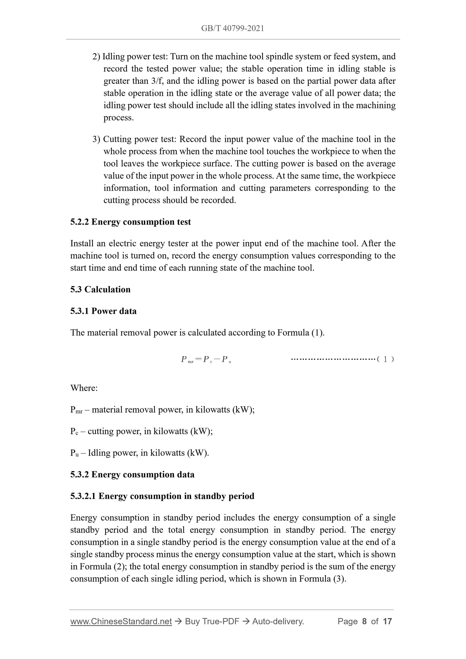
5.3.1 Power data
The material removal power is calculated according to Formula (1).
Where:
Pmr – material removal power, in kilowatts (kW);
Pc – cutting power, in kilowatts (kW);
Pu – Idling power, in kilowatts (kW).
5.3.2 Energy consumption data
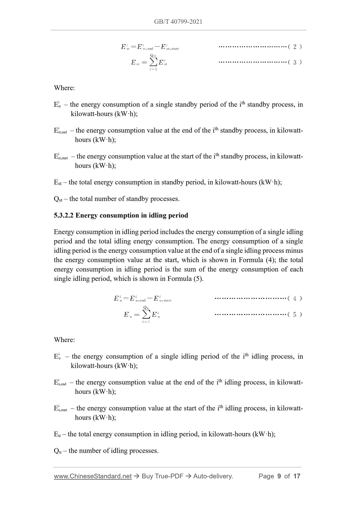
5.3.2.1 Energy consumption in standby period
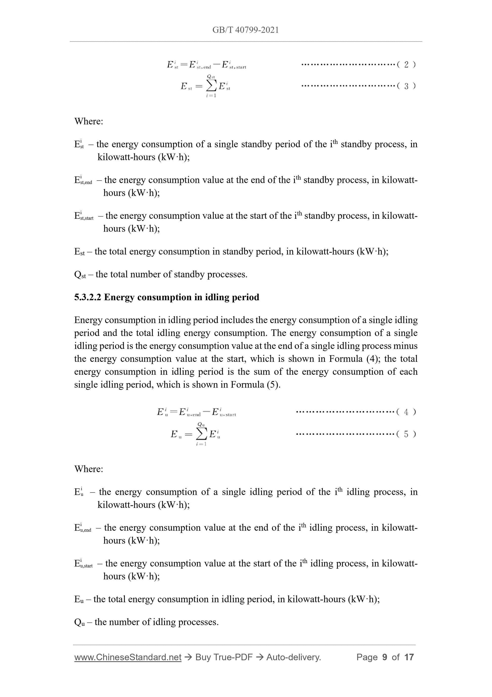
Energy consumption in standby period includes the energy consumption of a single
standby period and the total energy consumption in standby period. The energy
consumption in a single standby period is the energy consumption value at the end of a
single standby process minus the energy consumption value at the start, which is shown
in Formula (2); the total energy consumption in standby period is the sum of the energy
consumption of each single idling period, which is shown in Formula (3).
Where:
Ei st – the energy consumption of a single standby period of the ith standby process, in
kilowatt-hours (kW·h);
Ei st,end – the energy consumption value at the end of the ith standby process, in kilowatt-
hours (kW·h);
Ei st,start – the energy consumption value at the start of the ith standby process, in kilowatt-
hours (kW·h);
Est – the total energy consumption in standby period, in kilowatt-hours (kW·h);
Qst – the total number of standby processes.
5.3.2.2 Energy consumption in idling period
Energy consumption in idling period includes the energy consumption of a single idling
period and the total idling energy consumption. The energy consumption of a single
idling period is the energy consumption value at the end of a single idling process minus
the energy consumption value at the start, which is shown in Formula (4); the total
energy consumption in idling period is the sum of the energy consumption of each
single idling period, which is shown in Formula (5).
Where:
Ei u – the energy consumption of a single idling period of the ith idling process, in
kilowatt-hours (kW·h);
Ei u,end – the energy consumption value at the end of the ith idling process, in kilowatt-
hours (kW·h);
Ei u,start – the energy consumption value at the start of the ith idling process, in kilowatt-
hours (kW·h);
Eu – the total energy consumption in idling period, in kilowatt-hours (kW·h);
Qu – the number of idling processes.
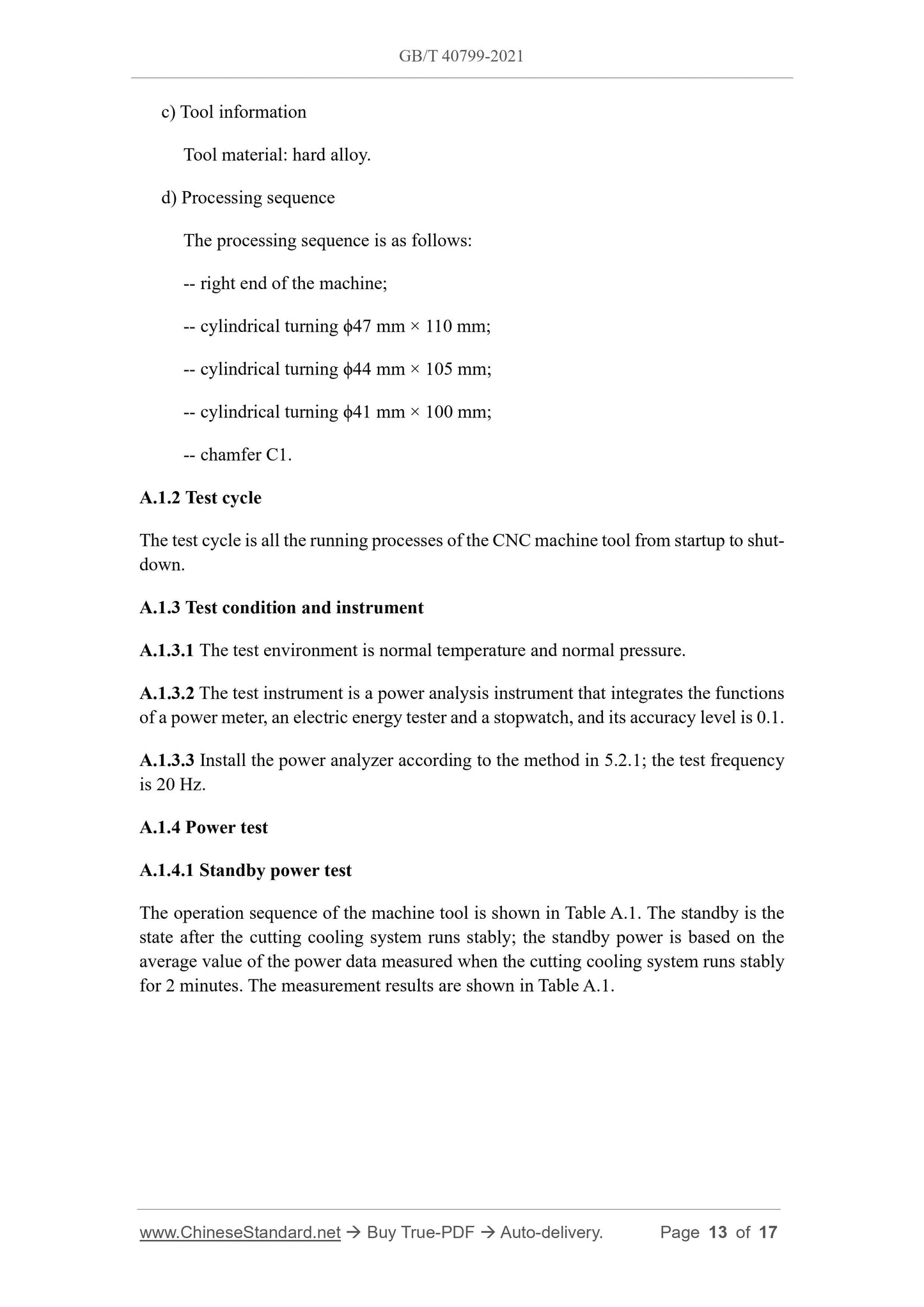
c) Tool information
Tool material: hard alloy.
d) Processing sequence
The processing sequence is as follows:
-- right end of the machine;
-- cylindrical turning ϕ47 mm × 110 mm;
-- cylindrical turning ϕ44 mm × 105 mm;
-- cylindrical turning ϕ41 mm × 100 mm;
-- chamfer C1.
A.1.2 Test cycle
The test cycle is all the running processes of the CNC machine tool from startup to shut-
down.
A.1.3 Test condition and instrument
A.1.3.1 The test environment is normal temperature and normal pressure.
A.1.3.2 The test instrument is a power analysis instrument that integrates the functions
of a power meter, an electric energy tester and a stopwatch, and its accuracy level is 0.1.
A.1.3.3 Install the power analyzer according to the method in 5.2.1; the test frequency
is 20 Hz.
A.1.4 Power test
A.1.4.1 Standby power test
The operation sequence of the machine tool is shown in Table A.1. The standby is the
state after the cutting cooling system runs stably; the standby power is based on the
average value of the power data measured when the cutting cooling system runs stably
for 2 minutes. The measurement results are shown in ...
Get QUOTATION in 1-minute: Click GB/T 40799-2021
Historical versions: GB/T 40799-2021
Preview True-PDF (Reload/Scroll if blank)
GB/T 40799-2021: Machining process -- Test methods for essential energy efficiency data
GB/T 40799-2021
NATIONAL STANDARD OF THE
PEOPLE’S REPUBLIC OF CHINA
ICS 25.020
CCS J 30
GB 40799-2021
Machining process - Test methods for essential energy
efficiency data
ISSUED ON: OCTOBER 11, 2021
IMPLEMENTED ON: MAY 01, 2022
Issued by: State Administration for Market Regulation;
Standardization Administration of the People’s Republic of China.
Table of Contents
FOREWORD ... 3
1 Scope ... 4
2 Normative references ... 4
3 Terms and definitions... 4
4 Scope of essential energy efficiency data ... 6
5 Test method and calculation ... 6
Appendix A (Informative) Application example of essential energy efficiency data test
in the machining process ... 12
Machining process - Test methods for essential energy
efficiency data
1 Scope
This document specifies the test and calculation methods for essential energy efficiency
data in the machining process.
This document applies to the test of essential energy efficiency data in the machining
process of metal cutting machine tools during machining.
2 Normative references
The following documents, in whole or in part, are normatively referenced in this
document and are indispensable for its application. For dated references, only the
version corresponding to that date is applicable to this document; for undated references,
the latest version (including all amendments) is applicable to this document.
GB/T 4863, General terminology of machine-building technology
GB/T 6477, Metal-cutting machine tools - Terminology
3 Terms and definitions
Terms and definitions determined by GB/T 4863, GB/T 6477, and the following ones
are applicable to this document.
3.1
machining process
The part or entire process for a machine tool to complete the machining of a workpiece.
3.2
standby
The state where the general power supply of the machine tool is turned on, and all other
systems of the machine tool used to support machining, except the spindle and the feed
system, are running.
3.3
idling
The state, in standby, where the spindle system or feed system of the machine tool is
turned on, and the spindle system or feed system is in the state where there is no cutting
load.
3.4
cutting
The running state where the machine tool is cutting and machining the workpiece.
3.5
standby power
The input power when the machine tool is in standby (3.2).
3.6
idling power
The input power when the machine tool is in idling (3.3).
3.7
cutting power
The input power when the machine tool is in cutting (3.4).
3.8
material removal power
The power increased for the machine tool to remove material.
3.9
energy consumption in standby period
The energy consumed by the machine tool in standby (3.2).
3.10
energy consumption in idling period
The energy consumed by the machine tool in idling (3.3).
3.11
energy consumption in cutting period
2) Idling power test: Turn on the machine tool spindle system or feed system, and
record the tested power value; the stable operation time in idling stable is
greater than 3/f, and the idling power is based on the partial power data after
stable operation in the idling state or the average value of all power data; the
idling power test should include all the idling states involved in the machining
process.
3) Cutting power test: Record the input power value of the machine tool in the
whole process from when the machine tool touches the workpiece to when the
tool leaves the workpiece surface. The cutting power is based on the average
value of the input power in the whole process. At the same time, the workpiece
information, tool information and cutting parameters corresponding to the
cutting process should be recorded.
5.2.2 Energy consumption test
Install an electric energy tester at the power input end of the machine tool. After the
machine tool is turned on, record the energy consumption values corresponding to the
start time and end time of each running state of the machine tool.
5.3 Calculation
5.3.1 Power data
The material removal power is calculated according to Formula (1).
Where:
Pmr – material removal power, in kilowatts (kW);
Pc – cutting power, in kilowatts (kW);
Pu – Idling power, in kilowatts (kW).
5.3.2 Energy consumption data
5.3.2.1 Energy consumption in standby period
Energy consumption in standby period includes the energy consumption of a single
standby period and the total energy consumption in standby period. The energy
consumption in a single standby period is the energy consumption value at the end of a
single standby process minus the energy consumption value at the start, which is shown
in Formula (2); the total energy consumption in standby period is the sum of the energy
consumption of each single idling period, which is shown in Formula (3).
Where:
Ei st – the energy consumption of a single standby period of the ith standby process, in
kilowatt-hours (kW·h);
Ei st,end – the energy consumption value at the end of the ith standby process, in kilowatt-
hours (kW·h);
Ei st,start – the energy consumption value at the start of the ith standby process, in kilowatt-
hours (kW·h);
Est – the total energy consumption in standby period, in kilowatt-hours (kW·h);
Qst – the total number of standby processes.
5.3.2.2 Energy consumption in idling period
Energy consumption in idling period includes the energy consumption of a single idling
period and the total idling energy consumption. The energy consumption of a single
idling period is the energy consumption value at the end of a single idling process minus
the energy consumption value at the start, which is shown in Formula (4); the total
energy consumption in idling period is the sum of the energy consumption of each
single idling period, which is shown in Formula (5).
Where:
Ei u – the energy consumption of a single idling period of the ith idling process, in
kilowatt-hours (kW·h);
Ei u,end – the energy consumption value at the end of the ith idling process, in kilowatt-
hours (kW·h);
Ei u,start – the energy consumption value at the start of the ith idling process, in kilowatt-
hours (kW·h);
Eu – the total energy consumption in idling period, in kilowatt-hours (kW·h);
Qu – the number of idling processes.
c) Tool information
Tool material: hard alloy.
d) Processing sequence
The processing sequence is as follows:
-- right end of the machine;
-- cylindrical turning ϕ47 mm × 110 mm;
-- cylindrical turning ϕ44 mm × 105 mm;
-- cylindrical turning ϕ41 mm × 100 mm;
-- chamfer C1.
A.1.2 Test cycle
The test cycle is all the running processes of the CNC machine tool from startup to shut-
down.
A.1.3 Test condition and instrument
A.1.3.1 The test environment is normal temperature and normal pressure.
A.1.3.2 The test instrument is a power analysis instrument that integrates the functions
of a power meter, an electric energy tester and a stopwatch, and its accuracy level is 0.1.
A.1.3.3 Install the power analyzer according to the method in 5.2.1; the test frequency
is 20 Hz.
A.1.4 Power test
A.1.4.1 Standby power test
The operation sequence of the machine tool is shown in Table A.1. The standby is the
state after the cutting cooling system runs stably; the standby power is based on the
average value of the power data measured when the cutting cooling system runs stably
for 2 minutes. The measurement results are shown in ...
Share