1
/
of
7
PayPal, credit cards. Download editable-PDF and invoice in 1 second!
GB/T 41655-2022 English PDF (GB/T41655-2022)
GB/T 41655-2022 English PDF (GB/T41655-2022)
Regular price
$245.00 USD
Regular price
Sale price
$245.00 USD
Unit price
/
per
Shipping calculated at checkout.
Couldn't load pickup availability
Delivery: 3 seconds. Download true-PDF + Invoice.
Get QUOTATION in 1-minute: Click GB/T 41655-2022
Historical versions: GB/T 41655-2022
Preview True-PDF (Reload/Scroll if blank)
GB/T 41655-2022: Non-destructive testing - Ultrasonic testing - Technique of testing claddings produced by welding, rolling and explosion
GB/T 41655-2022
GB
NATIONAL STANDARD OF THE
PEOPLE’S REPUBLIC OF CHINA
ICS 19.100
CCS J 04
Non-destructive Testing - Ultrasonic Testing - Technique of
Testing Claddings Produced by Welding, Rolling and
Explosion
(ISO 17405:2014, MOD)
ISSUED ON: JULY 11, 2022
IMPLEMENTED ON: FEBRUARY 1, 2023
Issued by: State Administration for Market Regulation;
Standardization Administration of the People’s Republic of China.
Table of Contents
Foreword ... 3
1 Scope ... 5
2 Normative References ... 5
3 Terms and Definitions ... 5
4 Ultrasonic Testing System ... 6
5 Test Preparation ... 12
6 Test Procedures ... 12
7 Test Report ... 13
Appendix A (informative) Determination of Focal Zone ... 15
Non-destructive Testing - Ultrasonic Testing - Technique of
Testing Claddings Produced by Welding, Rolling and
Explosion
1 Scope
This document specifies the technique of manual ultrasonic testing of claddings formed by
welding, rolling and explosion with steel as the base material using single or double crystal
probes.
This document is applicable to the testing of planar or volumetric discontinuities of the
claddings and interfaces.
This document does not stipulate the clauses for acceptance inspection, nor does it define the
scope of testing.
2 Normative References
The contents of the following documents constitute indispensable clauses of this document
through the normative references in the text. In terms of references with a specified date, only
versions with a specified date are applicable to this document. In terms of references without a
specified date, the latest version (including all the modifications) is applicable to this document.
GB/T 12604.1 Non-destructive Testing - Terminology - Ultrasonic Testing (GB/T 12604.1-
2020, ISO 5577:2017, MOD)
GB/T 19799.1 Non-destructive Testing - Ultrasonic Testing - Specification for Calibration
Block No.1 (GB/T 19799.1-2015, ISO 2400:2012, IDT)
ISO 22232-1 Non-destructive Testing - Characterization and Verification of Ultrasonic Test
Equipment - Part 1: Instruments
ISO 22232-2 Non-destructive Testing - Characterization and Verification of Ultrasonic Test
Equipment - Part 2: Probes
ISO 22232-3 Non-destructive Testing - Characterization and Verification of Ultrasonic Test
Equipment - Part 3: Combined Equipment
3 Terms and Definitions
What is defined in GB/T 12604.1, and the following terms and definitions are applicable to this
document.
3.1 test object
Test object refers to the component under test.
4 Ultrasonic Testing System
4.1 General Rules
The testing adopts ultrasonic pulse reflection technique. For planar and volumetric
discontinuities parallel to the test surface, a straight probe (single crystal or double crystal) and
longitudinal waves shall be adopted for the testing.
For discontinuities in other directions, longitudinal-wave double crystal angle probe or
transverse-wave angle probe may be adopted for the testing.
The nominal frequency of the probe shall be selected in accordance with the testing purpose
and material characteristics.
The probe frequency should be 2 MHz ~ 6 MHz. If the test verifies that the sensitivity satisfies
the requirements, probes with other frequencies can also be used.
The performance of the ultrasonic testing instrument shall comply with the requirements of ISO
22232-1. The performance of the probe shall comply with the requirements of ISO 22232-2.
The combined performance of the testing system shall be regularly inspected in accordance
with ISO 22232-3.
4.2 Requirements for Probes
4.2.1 Longitudinal-wave single crystal straight probe
The depth range of optimal sensitivity depends on the dimensions of the crystal plate. The depth
range should be determined based on the area where discontinuities are expected to be detected.
4.2.2 Longitudinal-wave double crystal straight probe
The depth range of optimal sensitivity (see Appendix A) depends on the dimensions of the
crystal plate and the roof angle. The depth range should be determined based on the area where
discontinuities are expected to be detected.
4.2.3 Longitudinal-wave double crystal angle probe
The longitudinal-wave refraction angle should be between 65 ~ 80. The selection of the tilt
angle, shape and dimensions of the crystal plate shall ensure that the depth range of optimal
sensitivity (see Appendix A) can cover the area where discontinuities are expected to be
detected.
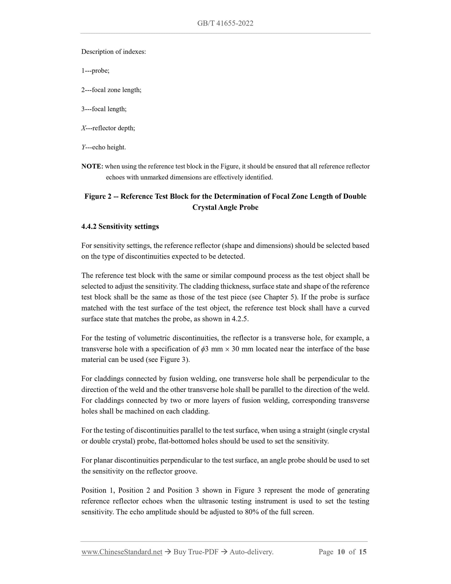
Description of indexes:
1---probe;
2---focal zone length;
3---focal length;
X---reflector depth;
Y---echo height.
NOTE: when using the reference test block in the Figure, it should be ensured that all reference reflector
echoes with unmarked dimensions are effectively identified.
Figure 2 -- Reference Test Block for the Determination of Focal Zone Length of Double
Crystal Angle Probe
4.4.2 Sensitivity settings
For sensitivity settings, the reference reflector (shape and dimensions) should be selected based
on the type of discontinuities expected to be detected.
The reference test block with the same or similar compound process as the test object shall be
selected to adjust the sensitivity. The cladding thickness, surface state and shape of the reference
test block shall be the same as those of the test piece (see Chapter 5). If the probe is surface
matched with the test surface of the test object, the reference test block shall have a curved
surface state that matches the probe, as shown in 4.2.5.
For the testing of volumetric discontinuities, the reflector is a transverse hole, for example, a
transverse hole with a specification of ϕ3 mm 30 mm located near the interface of the base
material can be used (see Figure 3).
For claddings connected by fusion welding, one transverse hole shall be perpendicular to the
direction of the weld and the other transverse hole shall be parallel to the direction of the weld.
For claddings connected by two or more layers of fusion welding, corresponding transverse
holes shall be machined on each cladding.
For the testing of discontinuities parallel to the test surface, when using a straight (single crystal
or double crystal) probe, flat-bottomed holes should be used to set the sensitivity.
For planar discontinuities perpendicular to the test surface, an angle probe should be used to set
the sensitivity on the reflector groove.
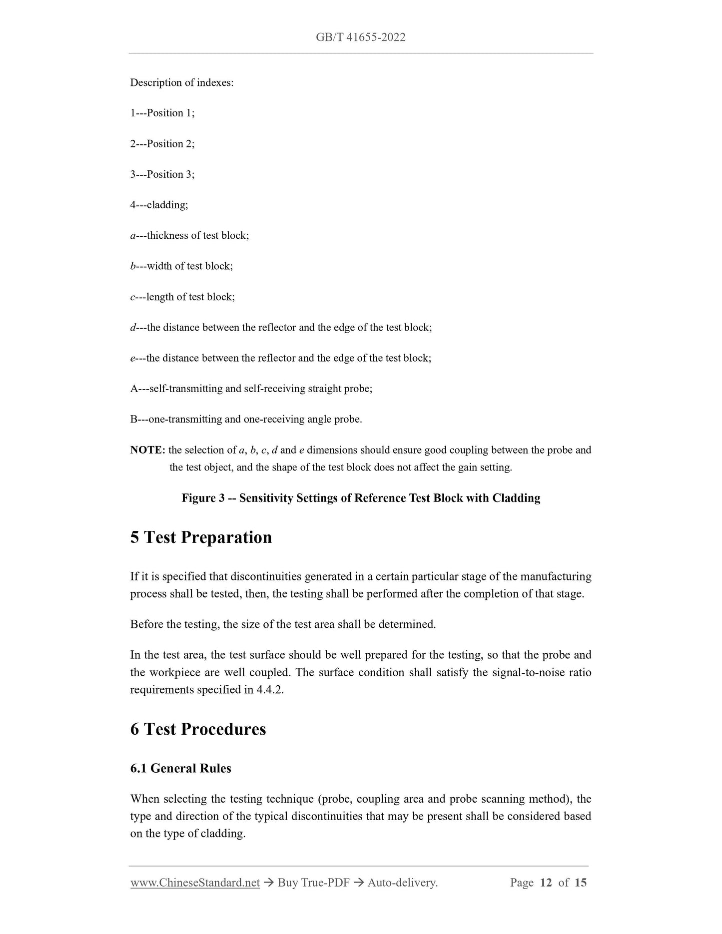
Position 1, Position 2 and Position 3 shown in Figure 3 represent the mode of generating
reference reflector echoes when the ultrasonic testing instrument is used to set the testing
sensitivity. The echo amplitude should be adjusted to 80% of the full screen.
Description of indexes:
1---Position 1;
2---Position 2;
3---Position 3;
4---cladding;
a---thickness of test block;
b---width of test block;
c---length of test block;
d---the distance between the reflector and the edge of the test block;
e---the distance between the reflector and the edge of the test block;
A---self-transmitting and self-receiving straight probe;
B---one-transmitting and one-receiving angle probe.
NOTE: the selection of a, b, c, d and e dimensions should ensure good coupling between the probe and
the test object, and the shape of the test block does not affect the gain setting.
Figure 3 -- Sensitivity Settings of Reference Test Block with Cladding
5 Test Preparation
If it is specified that discontinuities generated in a certain particular stage of the manufacturing
process shall be tested, ...
Get QUOTATION in 1-minute: Click GB/T 41655-2022
Historical versions: GB/T 41655-2022
Preview True-PDF (Reload/Scroll if blank)
GB/T 41655-2022: Non-destructive testing - Ultrasonic testing - Technique of testing claddings produced by welding, rolling and explosion
GB/T 41655-2022
GB
NATIONAL STANDARD OF THE
PEOPLE’S REPUBLIC OF CHINA
ICS 19.100
CCS J 04
Non-destructive Testing - Ultrasonic Testing - Technique of
Testing Claddings Produced by Welding, Rolling and
Explosion
(ISO 17405:2014, MOD)
ISSUED ON: JULY 11, 2022
IMPLEMENTED ON: FEBRUARY 1, 2023
Issued by: State Administration for Market Regulation;
Standardization Administration of the People’s Republic of China.
Table of Contents
Foreword ... 3
1 Scope ... 5
2 Normative References ... 5
3 Terms and Definitions ... 5
4 Ultrasonic Testing System ... 6
5 Test Preparation ... 12
6 Test Procedures ... 12
7 Test Report ... 13
Appendix A (informative) Determination of Focal Zone ... 15
Non-destructive Testing - Ultrasonic Testing - Technique of
Testing Claddings Produced by Welding, Rolling and
Explosion
1 Scope
This document specifies the technique of manual ultrasonic testing of claddings formed by
welding, rolling and explosion with steel as the base material using single or double crystal
probes.
This document is applicable to the testing of planar or volumetric discontinuities of the
claddings and interfaces.
This document does not stipulate the clauses for acceptance inspection, nor does it define the
scope of testing.
2 Normative References
The contents of the following documents constitute indispensable clauses of this document
through the normative references in the text. In terms of references with a specified date, only
versions with a specified date are applicable to this document. In terms of references without a
specified date, the latest version (including all the modifications) is applicable to this document.
GB/T 12604.1 Non-destructive Testing - Terminology - Ultrasonic Testing (GB/T 12604.1-
2020, ISO 5577:2017, MOD)
GB/T 19799.1 Non-destructive Testing - Ultrasonic Testing - Specification for Calibration
Block No.1 (GB/T 19799.1-2015, ISO 2400:2012, IDT)
ISO 22232-1 Non-destructive Testing - Characterization and Verification of Ultrasonic Test
Equipment - Part 1: Instruments
ISO 22232-2 Non-destructive Testing - Characterization and Verification of Ultrasonic Test
Equipment - Part 2: Probes
ISO 22232-3 Non-destructive Testing - Characterization and Verification of Ultrasonic Test
Equipment - Part 3: Combined Equipment
3 Terms and Definitions
What is defined in GB/T 12604.1, and the following terms and definitions are applicable to this
document.
3.1 test object
Test object refers to the component under test.
4 Ultrasonic Testing System
4.1 General Rules
The testing adopts ultrasonic pulse reflection technique. For planar and volumetric
discontinuities parallel to the test surface, a straight probe (single crystal or double crystal) and
longitudinal waves shall be adopted for the testing.
For discontinuities in other directions, longitudinal-wave double crystal angle probe or
transverse-wave angle probe may be adopted for the testing.
The nominal frequency of the probe shall be selected in accordance with the testing purpose
and material characteristics.
The probe frequency should be 2 MHz ~ 6 MHz. If the test verifies that the sensitivity satisfies
the requirements, probes with other frequencies can also be used.
The performance of the ultrasonic testing instrument shall comply with the requirements of ISO
22232-1. The performance of the probe shall comply with the requirements of ISO 22232-2.
The combined performance of the testing system shall be regularly inspected in accordance
with ISO 22232-3.
4.2 Requirements for Probes
4.2.1 Longitudinal-wave single crystal straight probe
The depth range of optimal sensitivity depends on the dimensions of the crystal plate. The depth
range should be determined based on the area where discontinuities are expected to be detected.
4.2.2 Longitudinal-wave double crystal straight probe
The depth range of optimal sensitivity (see Appendix A) depends on the dimensions of the
crystal plate and the roof angle. The depth range should be determined based on the area where
discontinuities are expected to be detected.
4.2.3 Longitudinal-wave double crystal angle probe
The longitudinal-wave refraction angle should be between 65 ~ 80. The selection of the tilt
angle, shape and dimensions of the crystal plate shall ensure that the depth range of optimal
sensitivity (see Appendix A) can cover the area where discontinuities are expected to be
detected.
Description of indexes:
1---probe;
2---focal zone length;
3---focal length;
X---reflector depth;
Y---echo height.
NOTE: when using the reference test block in the Figure, it should be ensured that all reference reflector
echoes with unmarked dimensions are effectively identified.
Figure 2 -- Reference Test Block for the Determination of Focal Zone Length of Double
Crystal Angle Probe
4.4.2 Sensitivity settings
For sensitivity settings, the reference reflector (shape and dimensions) should be selected based
on the type of discontinuities expected to be detected.
The reference test block with the same or similar compound process as the test object shall be
selected to adjust the sensitivity. The cladding thickness, surface state and shape of the reference
test block shall be the same as those of the test piece (see Chapter 5). If the probe is surface
matched with the test surface of the test object, the reference test block shall have a curved
surface state that matches the probe, as shown in 4.2.5.
For the testing of volumetric discontinuities, the reflector is a transverse hole, for example, a
transverse hole with a specification of ϕ3 mm 30 mm located near the interface of the base
material can be used (see Figure 3).
For claddings connected by fusion welding, one transverse hole shall be perpendicular to the
direction of the weld and the other transverse hole shall be parallel to the direction of the weld.
For claddings connected by two or more layers of fusion welding, corresponding transverse
holes shall be machined on each cladding.
For the testing of discontinuities parallel to the test surface, when using a straight (single crystal
or double crystal) probe, flat-bottomed holes should be used to set the sensitivity.
For planar discontinuities perpendicular to the test surface, an angle probe should be used to set
the sensitivity on the reflector groove.
Position 1, Position 2 and Position 3 shown in Figure 3 represent the mode of generating
reference reflector echoes when the ultrasonic testing instrument is used to set the testing
sensitivity. The echo amplitude should be adjusted to 80% of the full screen.
Description of indexes:
1---Position 1;
2---Position 2;
3---Position 3;
4---cladding;
a---thickness of test block;
b---width of test block;
c---length of test block;
d---the distance between the reflector and the edge of the test block;
e---the distance between the reflector and the edge of the test block;
A---self-transmitting and self-receiving straight probe;
B---one-transmitting and one-receiving angle probe.
NOTE: the selection of a, b, c, d and e dimensions should ensure good coupling between the probe and
the test object, and the shape of the test block does not affect the gain setting.
Figure 3 -- Sensitivity Settings of Reference Test Block with Cladding
5 Test Preparation
If it is specified that discontinuities generated in a certain particular stage of the manufacturing
process shall be tested, ...
Share